Fog/Driving Light LED Gauge Cluster Indicators
 04-20-2008, 08:09 AM
#1
Fog/Driving Light LED Gauge Cluster Indicators
 I have had a few questions about my LED indicators on my dash. Here is a brief write up on that portion of my Hella light install. Not all light switches have lighted indications as part of the switch so this makes a very nice clean and effective method of adding something a little more 'factory' in a way to remind you that you left your lights on.
 Disclaimer: This write up is for educational purposes only. Any use or application of this procedure is done so at the risk of the installer/owner. The author and YotaTech are not responsible for any modifications done to any vehicle using these or any other related procedures contained in this write up. Descriptions and photographs are the sole property and copyright of the author and may not be copied or distributed without written consent. Links to this article may be allowed but are protected by all US copyrights. Use of specific products along with any photographs of such items remains the copyrighted property of the copyright holder and is not an endorsement of any specific company or items.
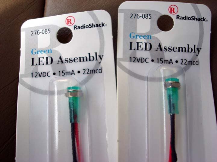
You will need to go to Radio Shack and check with the guys there and ask them for the contained LED's that already have the holder and resistor installed. I used 276-085, they were green but also the only ones they had that were preassembled. It worked for me as I did not do any fancy light upgrades and color changes to the OEM lighting in the gauge cluster. Other wise you have to purchase the LED color you want (which are domed), the holder AND the resistor that will drop the vehicle supplied voltage from 12vdc to around 5vdc. After about an hour of soldering, shrink wrapping the leads then installing in holders, you'll wish you had just purchased the pre-mades:
Removal of the dash gauge cluster:
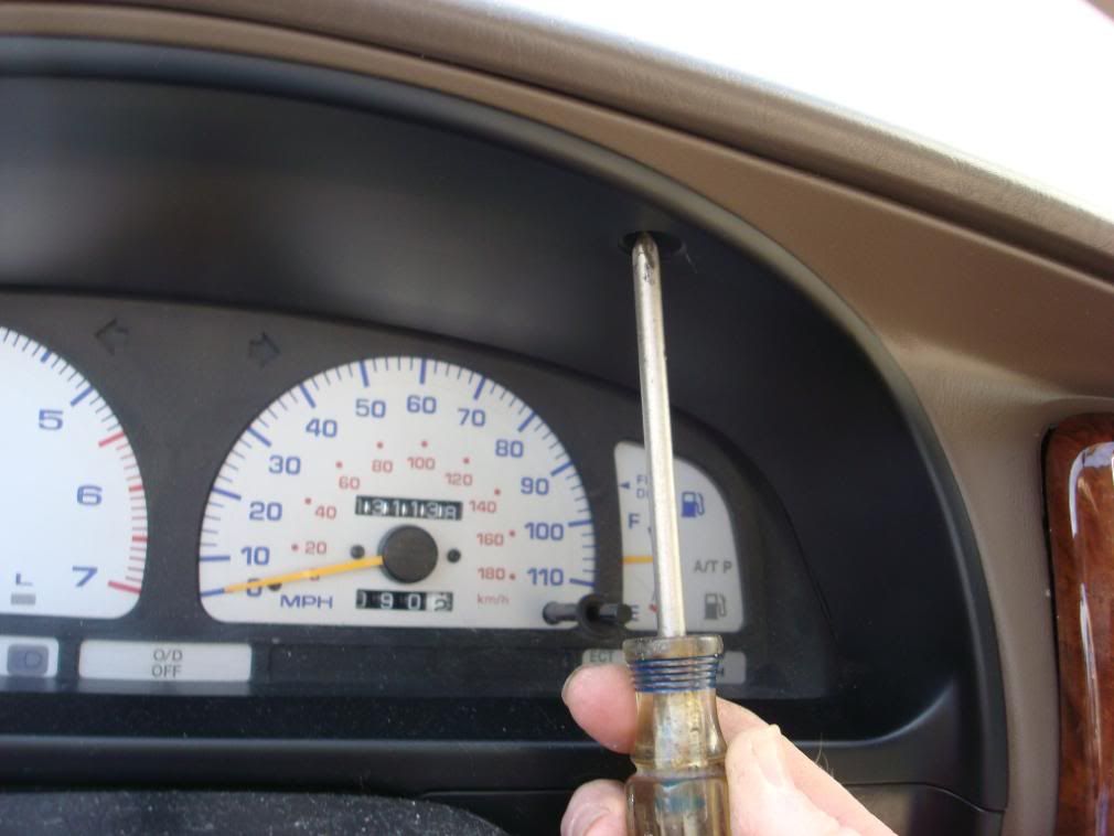
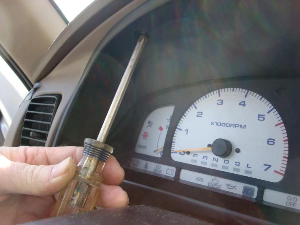
Remove the two screws in the top of the gauge cluster bezel, one on either side
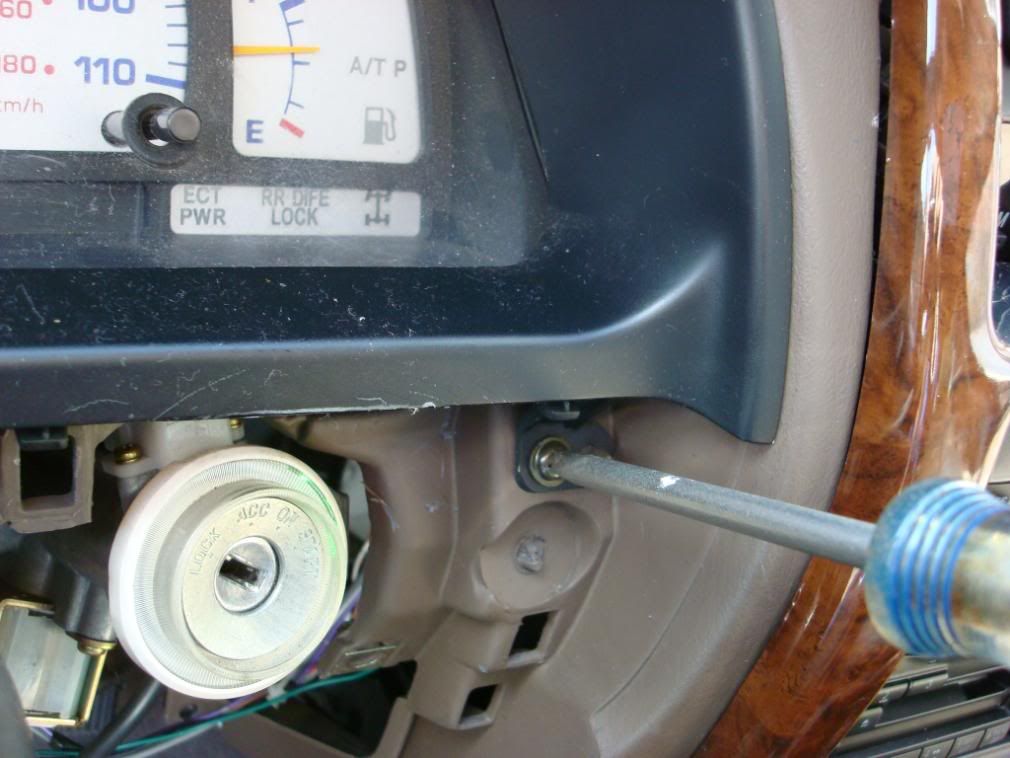
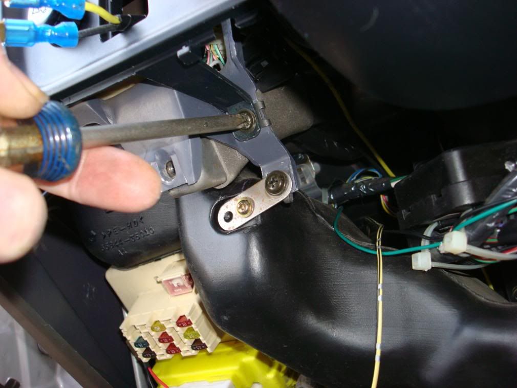
Remove the ignition cover, it will just pop off with a little persuasion and the lower dash panel on the left side of the steering column, there are 4 10 mm bolts in recessed holes. With those off you will see two screws that will need to be removed from the lower part of the bezel.
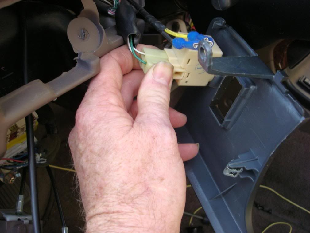
When you pull the bezel out, you will need to disconnect the dash dimmer connector. Just press down on the tab and pull. Be sure to remove any other leads for any switch that may be installed in the bezel as well.
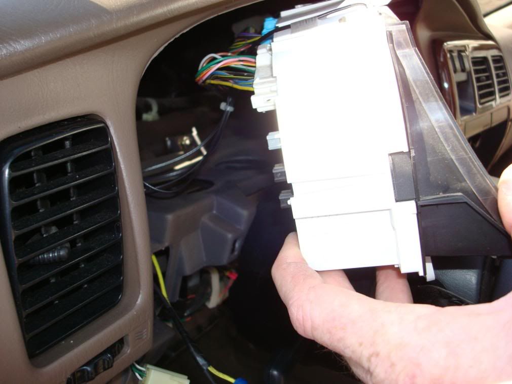
After removal of the gauge cluster bezel you will pull the gauge cluster itself.
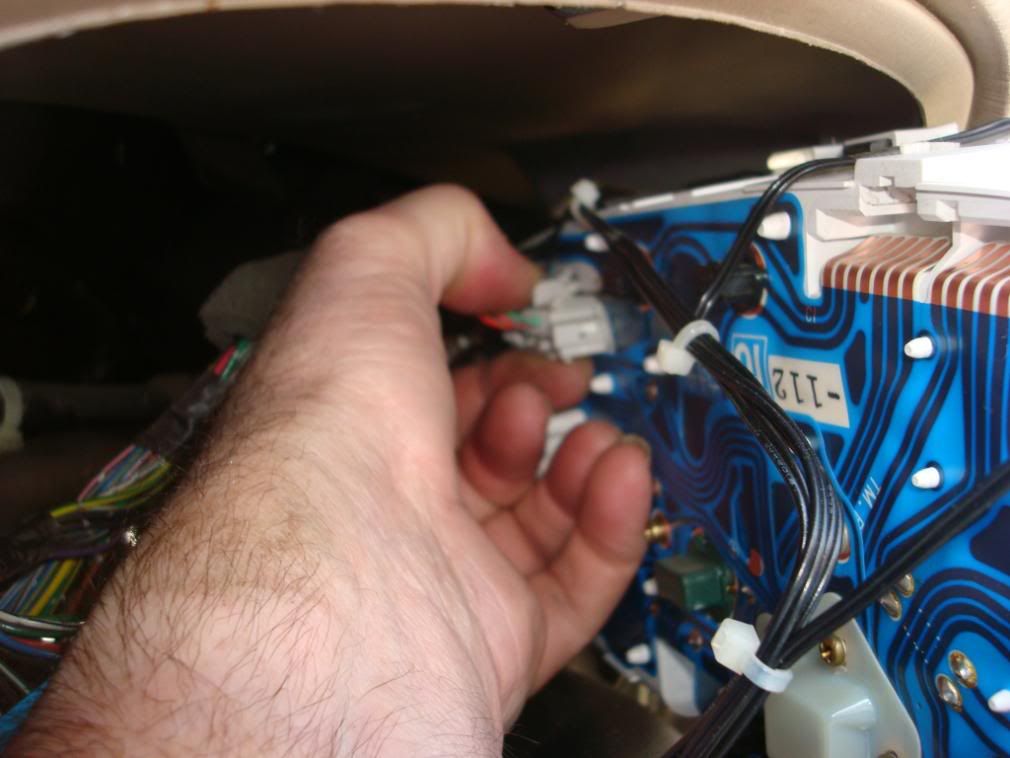
There are 4 screws holding the gauge cluster in place along with several connectors in the rear of the cluster.
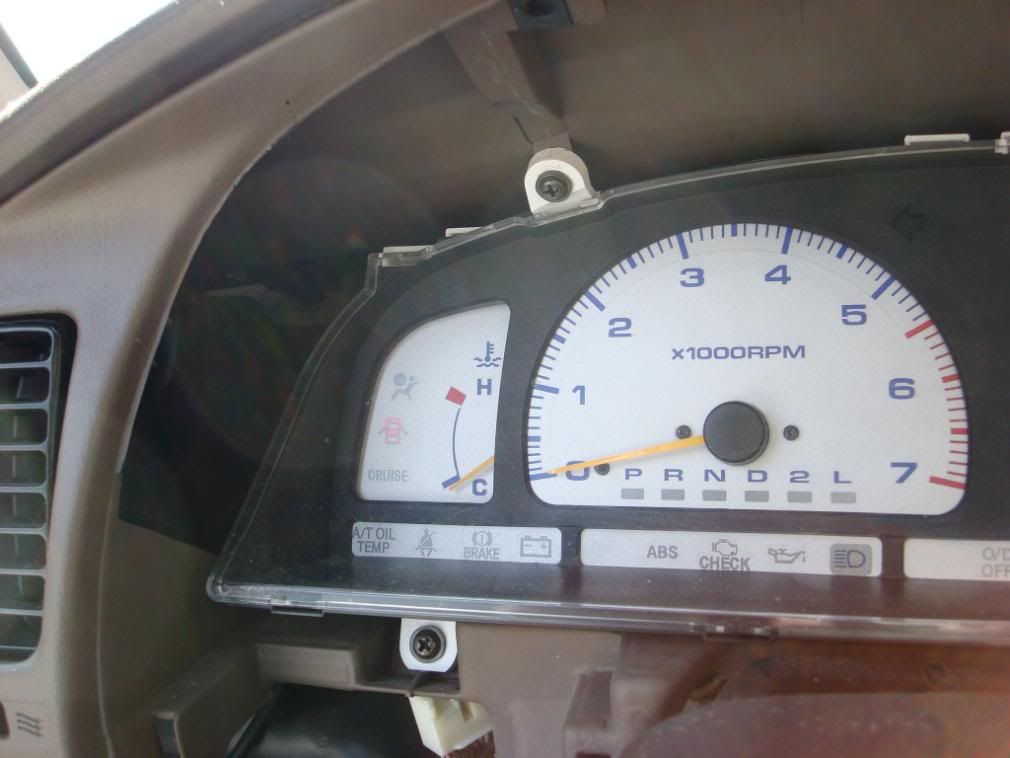
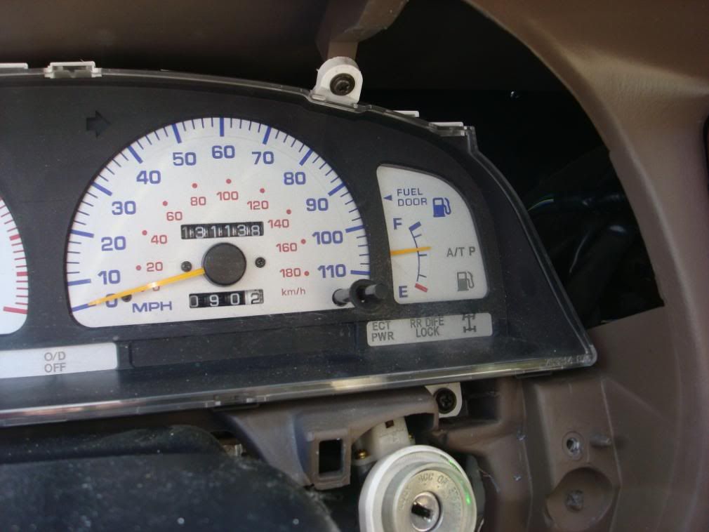
After you remove those 4 screws you will begin by gently pulling the gauge cluster out from the left side. You will feel tension, but pull it out enough to reveal the first connector. Press down on the tab at the top of the connector and gently pull it out of the cluster.
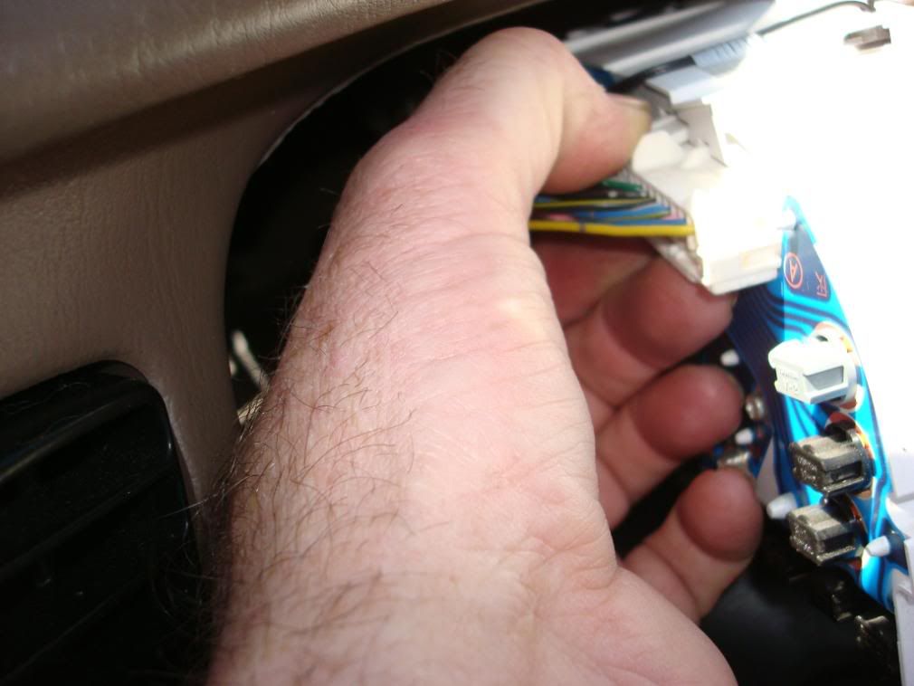
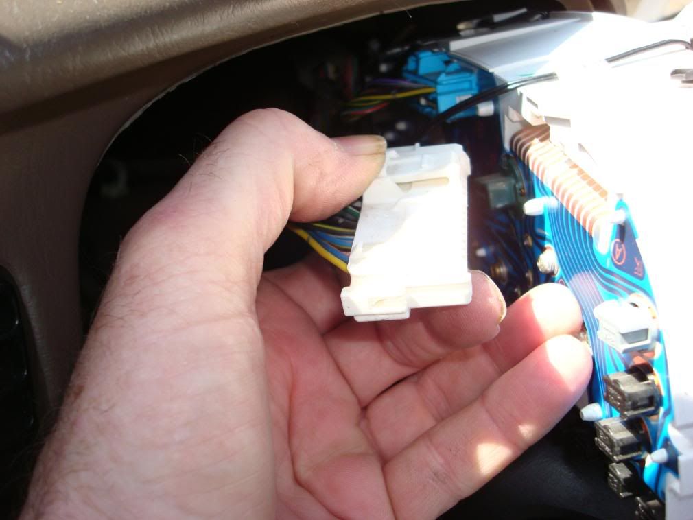
Work your way towards the right side of the cluster removing each of the remaining 3 connectors the same way
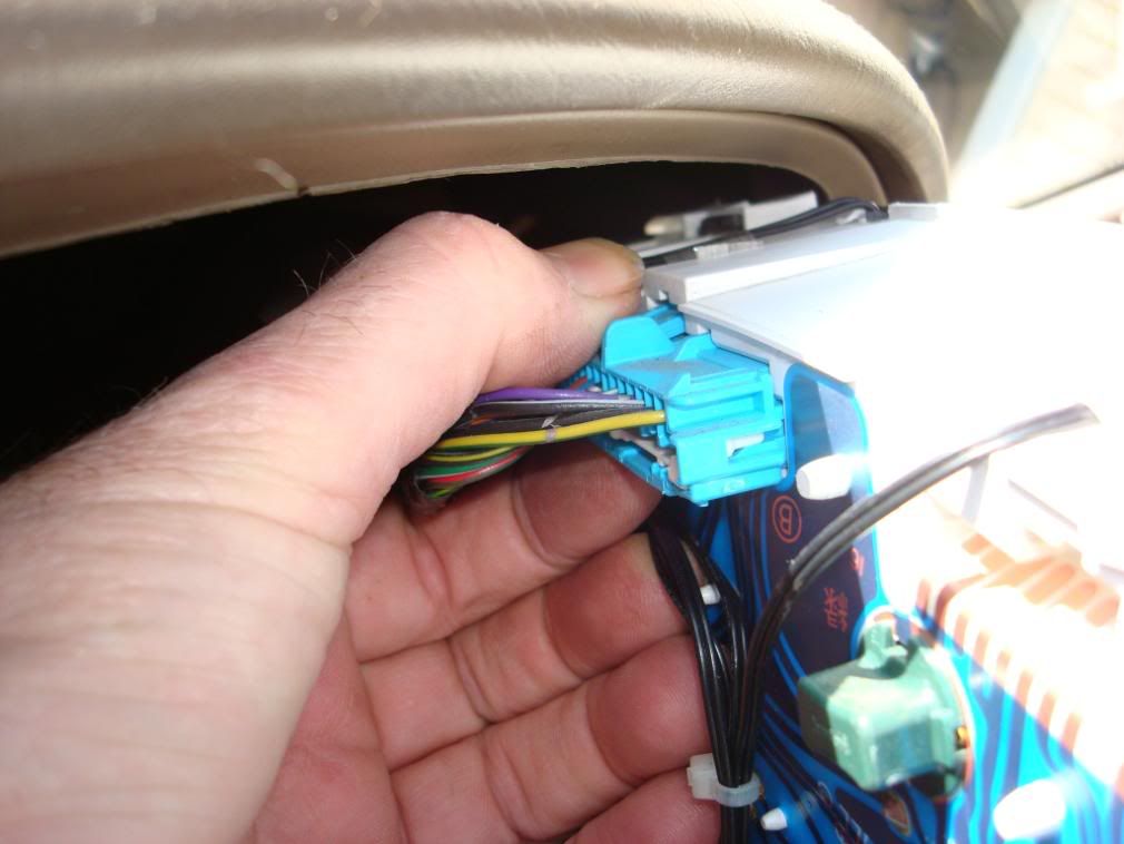
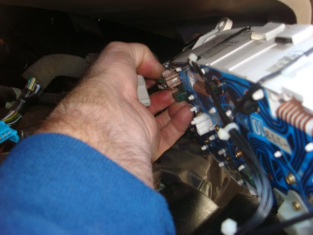
Set the cluster aside.
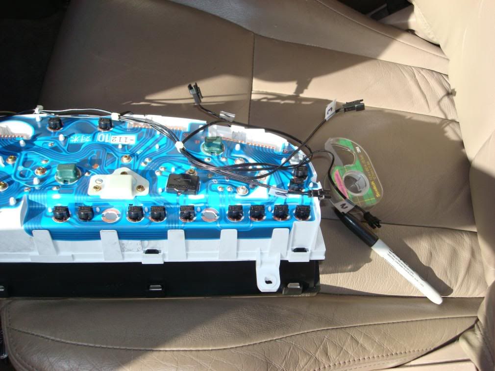
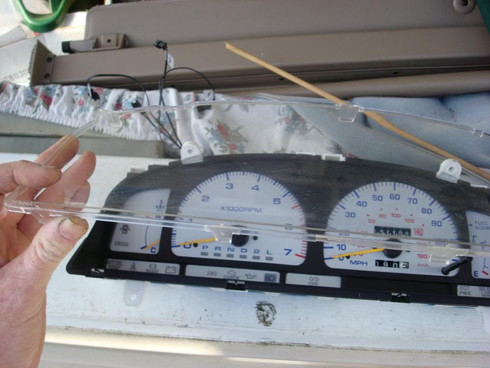
Removal of the gauge cluster protective plastic cover:
There are numerous tabs that will need to be pressed downward to free the protective cover from the cluster.
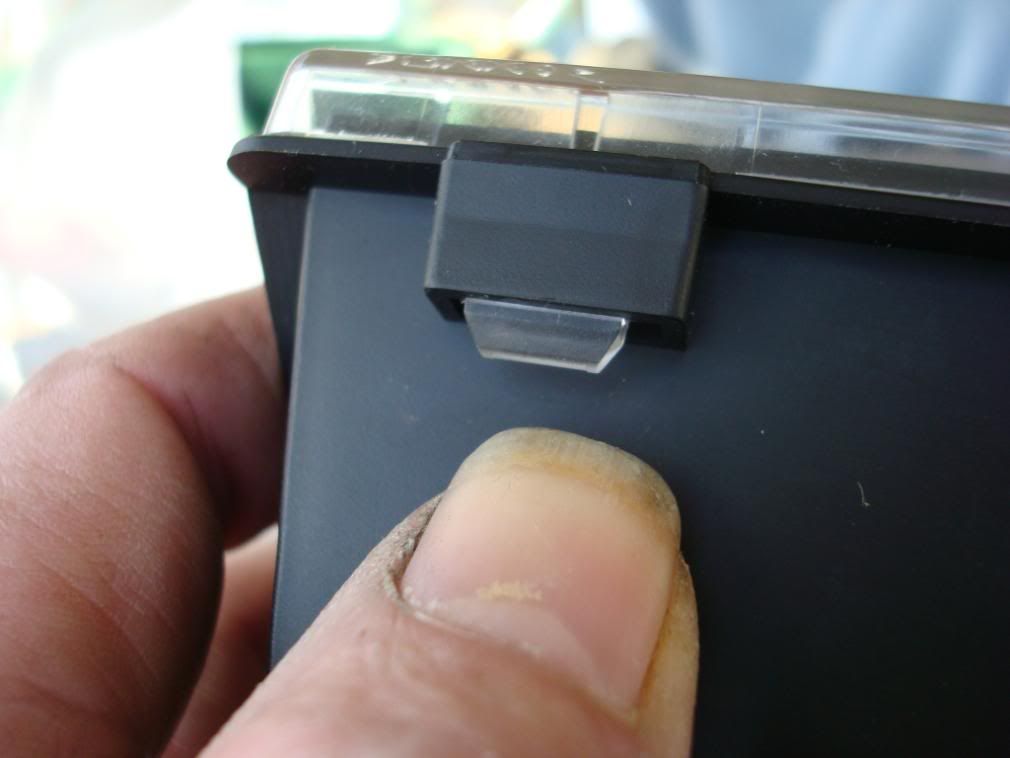
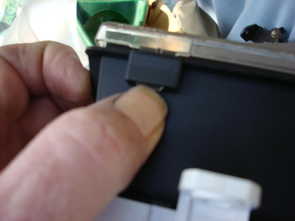
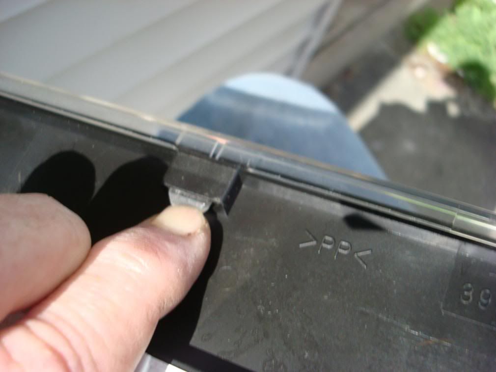
Work your way completely around the outer edge. After releasing all the tabs out, remove the plastic cover. This would be the same procedure if you desired to dress up the inner black gauge bezel, such as making it colored, carbon fiber or aluminum.
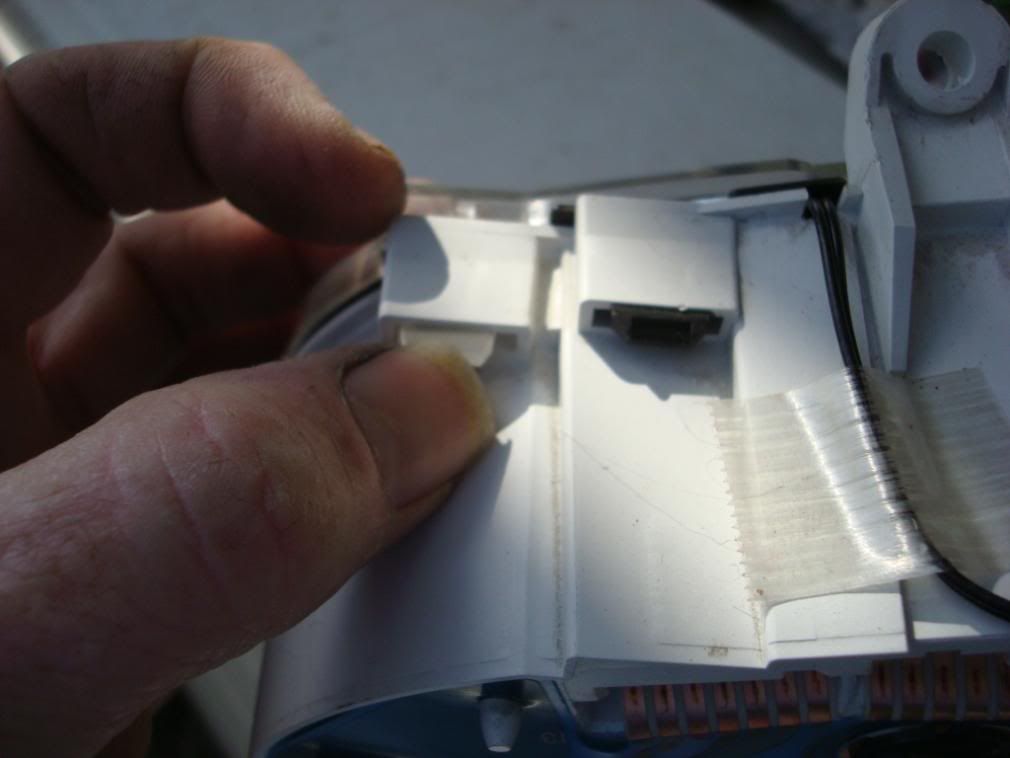
Depending on how many you are planning to install will determine where you want to locate the LED in the gauge cluster. I must caution you, I was very lucky when I put mine in. The gauge cluster when it goes back into the dash, if you put the LEDs in too close to the gauge face, or too far to one side or the other, they will interfere with your installing the gauge cluster back in the dash. Be sure to examine the length of the pre-made LEDs and then figure out the best location for your LEDs and their respective leads. Note where the gauge cluster fits back into the dash. Pre fit the cluster to help in determining the best location for your LEDs.
Installing and connecting the LEDs.
There should be some instruction on the packaging that tells you which leg of the LED is + and the other is -. Make sure you wire these correctly. LEDs only work when biased in one direction. These are diodes and only allow electron flow in ONE direction.
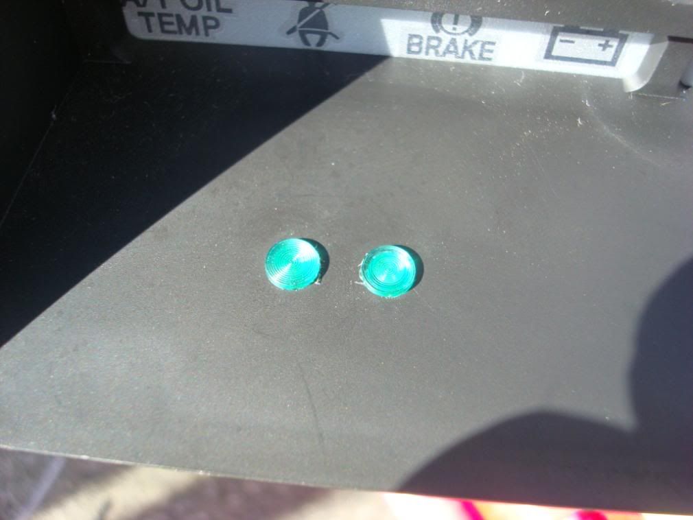
Nice thing about these pre-assembled LEDs besides having every thing there is they are flush and you use a lock nut to hold them in place vice the plastic push fit holders which tend to not stay put and require some sort of adhesive such as hot glue to help keep them permanently installed.
After finding the right location you need, drill the hole just the size needed to insert the LED.
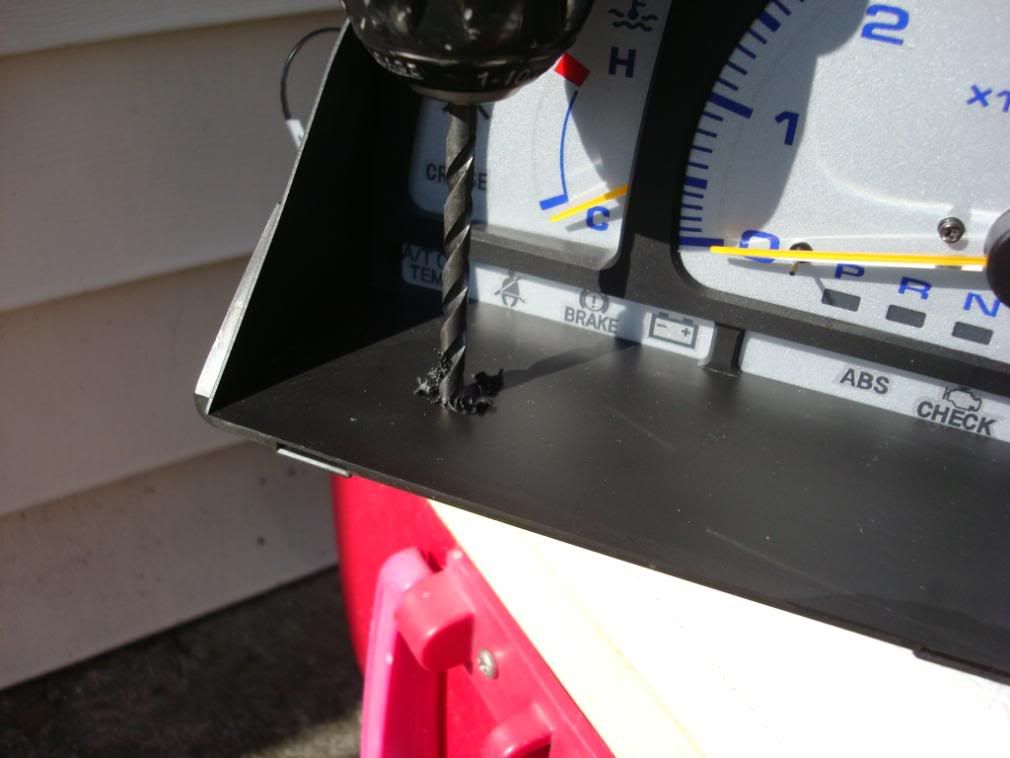
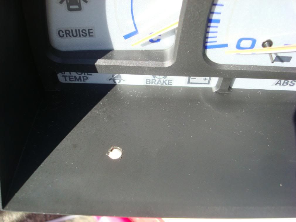
Install the LED in the hole so the base is flush in the hole.
Attach the locking nut.
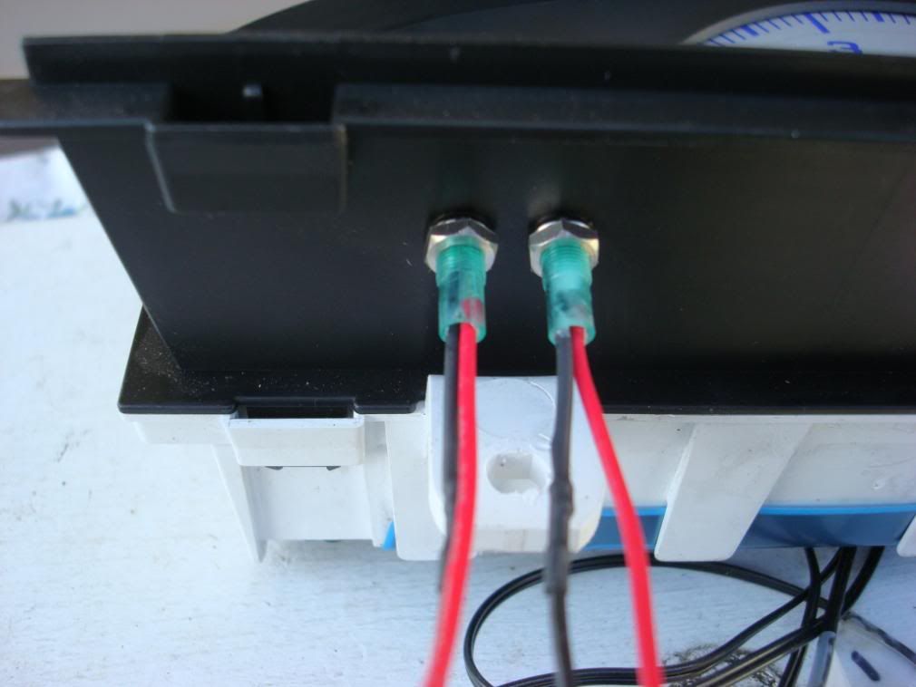
You will need to crimp on extension wires to the LED leads. I mention this as if you ever need to remove the LED or the switch if you have then directly crimped you loose wire length. I also put plug in connectors on the leads so that I could remove the switch and leave the LED installed.
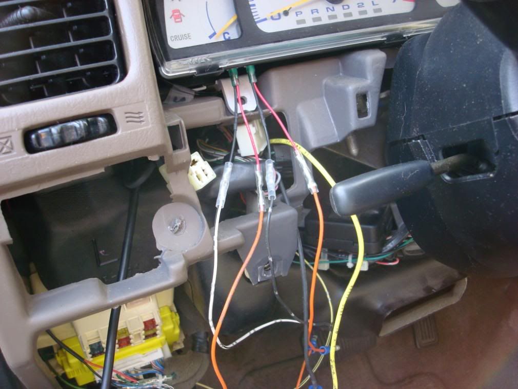
Hook up your switches with the appropriate lead then using the corresponding lead (remember + to +) from the switch. Cut that lead leaving enough space to strip about 3/8" insulation as you will take the LED '+' lead and splice one end of the switch wire and the LED lead together in the SAME END of the splice. Next you will connect the other end of your crimp to the switch lead. What you end up with is a 'Y' looking wire splice.
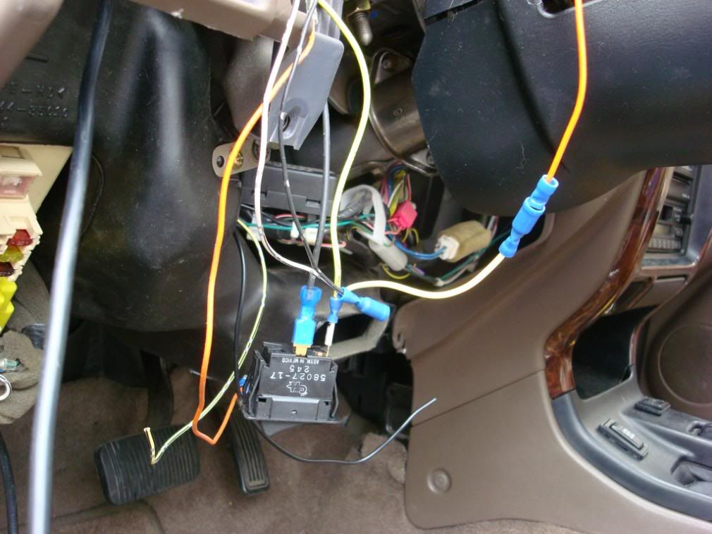
This picture is the Orange lead spliced into the white lead from the switch. You need to be sure to understand in what direction the current is flowing to and from the switch. You want the power for the LED to be on the "switched" side of current flow. If you don't have it on the after side of the switch, then the LED will be on all the time as you have 12vdc potential sitting on the incoming side of the switch.
The negative end of the LED will be wired to a common ground point. In other words, the LED is actually just a pick off for power to turn it on, while the other lead is connected to chassis GROUND.
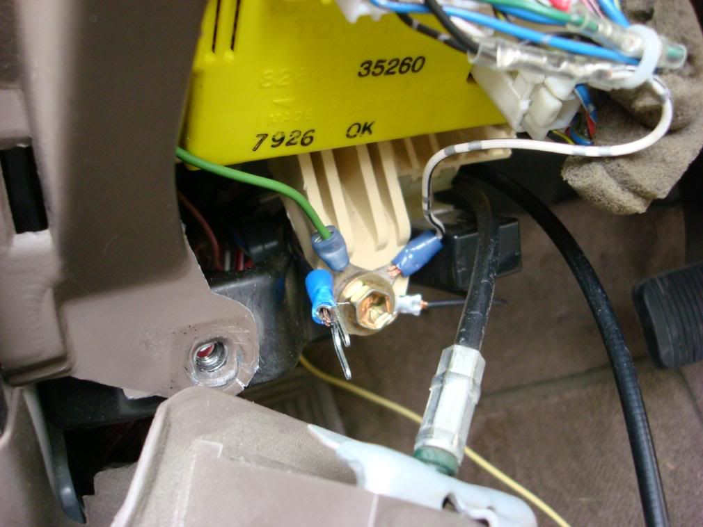
If you use more then one LED, crimp them all into one loop end terminal and attach to a common ground. I used the mount screw for the Integration relay which is just under the lower dash panel next to the left side of the lower dash panel.
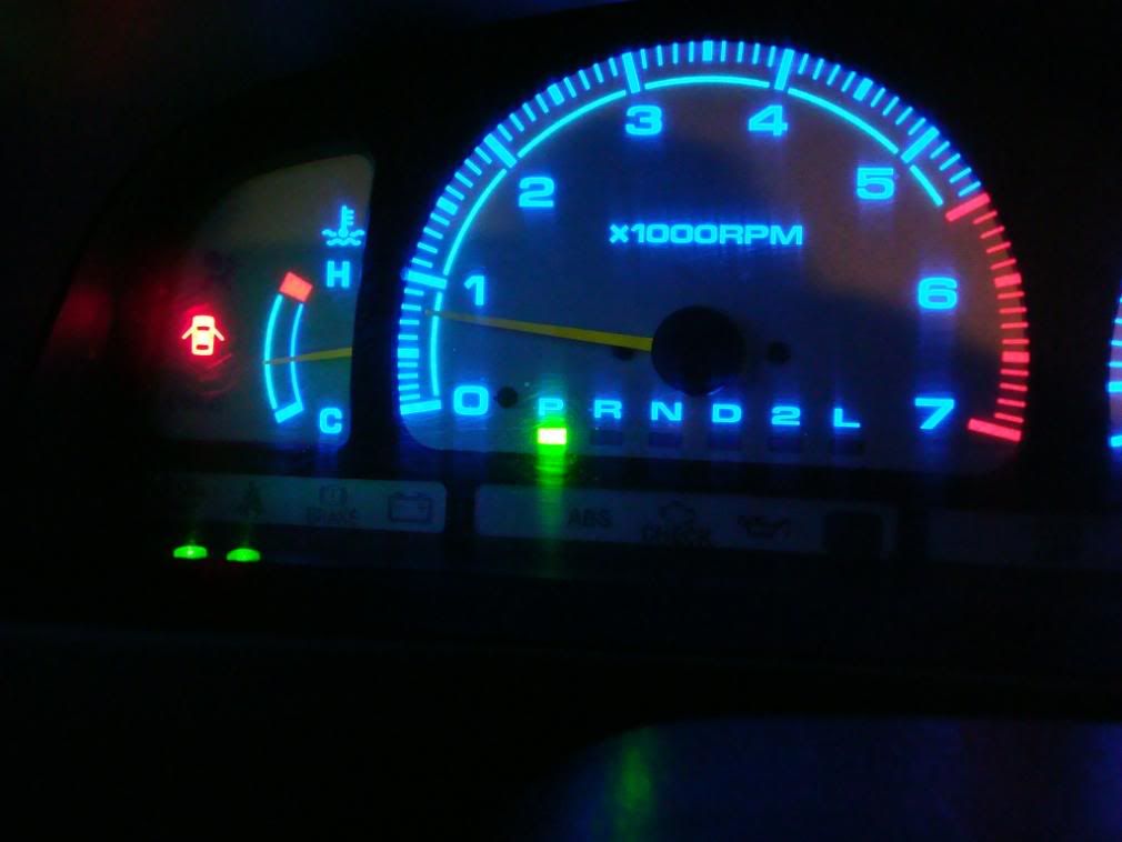
If you put these all in the correct order and location, when you press the rocker to 'ON' then the LED for that light will turn on.


Thread
Thread Starter
Forum
Replies
Last Post
nframe
3.4 Swaps
3
08-16-2015 09:03 AM
Esibnitsud
86-95 Trucks & 4Runners
11
07-30-2015 08:21 PM


