LED Side Marker Lights
 03-31-2008, 07:34 AM
#1
LED Side Marker Lights
Side Marker install.
NOTE:
Disclaimer: This modification is not part of any OEM application and as such carries no warranty of any kind. Any modification to your vehicle using these recommendations contained within this article is at the owner/operator/installers own risk. While I have performed this installation on my own vehicle each vehicle may be different depending on year and options. Please read all instruction before proceeding. Remember you do so at your own risk.
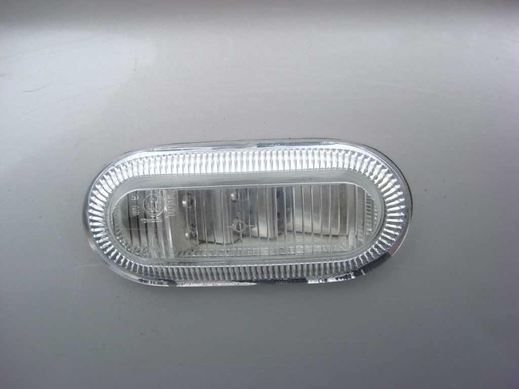
There are several quality side marker on many of the newer vehicles out there. Some now are LED as well as incandescent. I chose to use the newer LED side markers. These are found on many of the later "new" style VW Beetles. You can order/purchase form most any VW dealer. The lamp fixtures themselves are just under $43 each and then you have to procure the cable ends. These may be a bit more difficult to locate as these are the ends that are part of the cable harness and plug into the marker socket.
I located mine in a local wrecking yard. Cost will be abut � or even less. One important factor to remember when you try to remove these from a wrecked vehicle, it will require a #20 TORX bit screw driver and you need to get to the back side of the marker. On the VW it is extremely difficult to remove these unless the dash has been removed or the fenders have been loosened or pulled. Many yards prefer that you do not remove the markers from good fenders.
To remove the marker from the fender, you need to completely loosen the TORX screws which allows the two piece hold downs to swing inwards towards the connector of the marker. Once loosened the markers can be easily removed and the cable disconnected or cut leaving a useful wire end for splicing.
I started with the left fender. Select the location where you will want to mount the marker lights. Remember that these marker lights are a bit deeper then most other marker lights either from a parts store or from the auto maker.
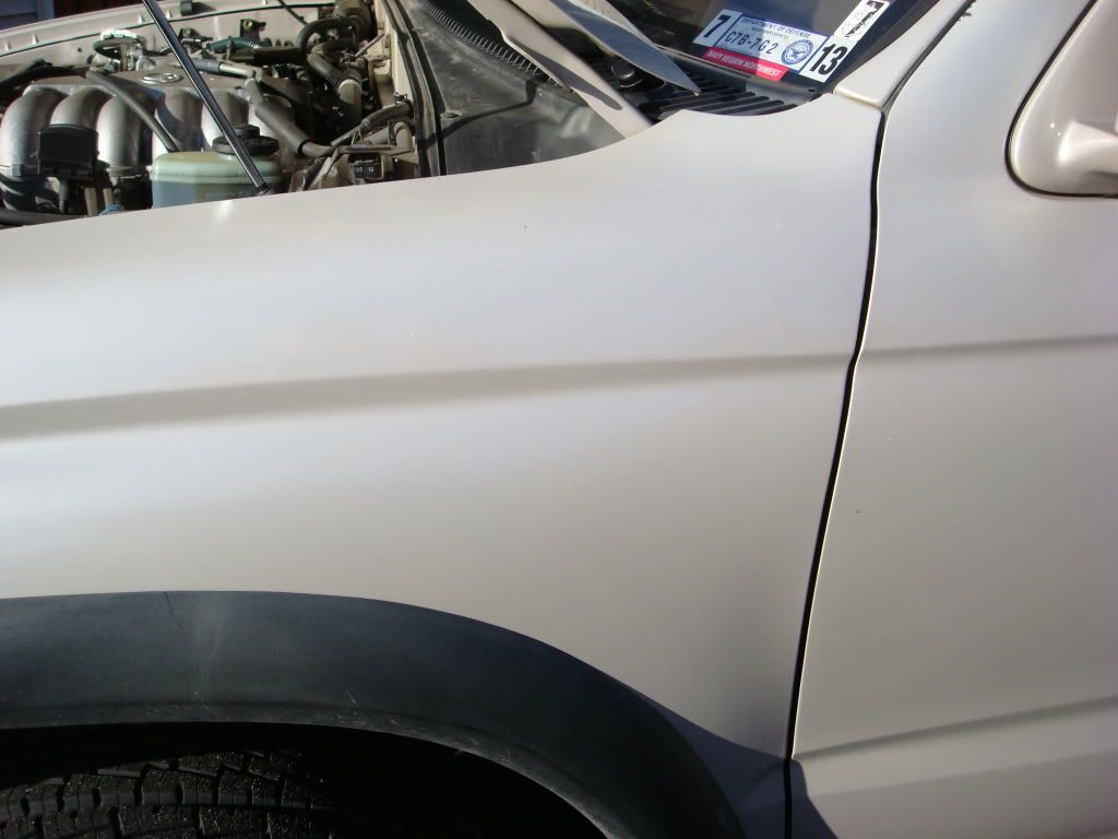
I would recommend the mounting location I selected as it will be at an excellent height and will clear the interior of the fender when installed. Start from the rear edge of the fender and measure 3 inches. From the top edge of the fender side ridge, measure down 2 inches. This will be your top most edge and rear most edge of the hole you will need to cut into the fender for mounting.
Next you will want to make a template. You can either use a piece of sheet metal such as Bob described or in my case I used a cardboard insert from a Pepsi case. I then used the rubber gasket from the light and drew out the interior of the gasket. Then using the same marker pen re-trace the outline only make the image about 1/8th of an inch larger
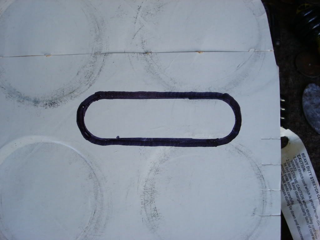
Carefully cut out the oval along the outer edge of your line. Place the template on the fender using your reference marks of 2 and 3 inches and secure with tape.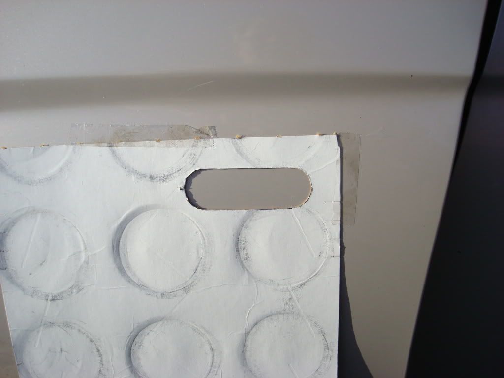
Trace out the oval onto the fender.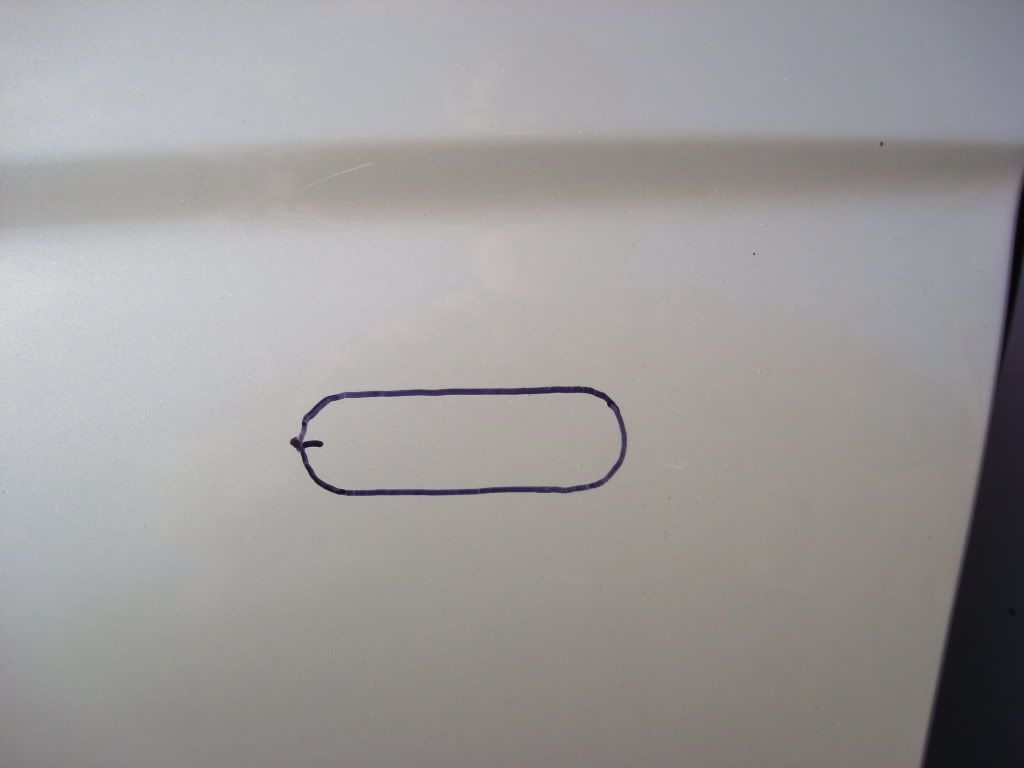
You will note that there is a small ridge fin on the marker light to designate which end is towards the front of the vehicle. Mark this as well.
If you would rather remove the fender completely from the vehicle, you will need to remove the bumper to get to the front securing bolt in the fender. This would be the best method of installing these side markers. As I do not have the luxury of leaving my vehicle in a warm dry garage and not needing to drive it for a few days, I opted to do a partial removal.
Next we will need to partially remove the fender so that our TORX screwdriver will be able to be used to install the marker in the finished hole.
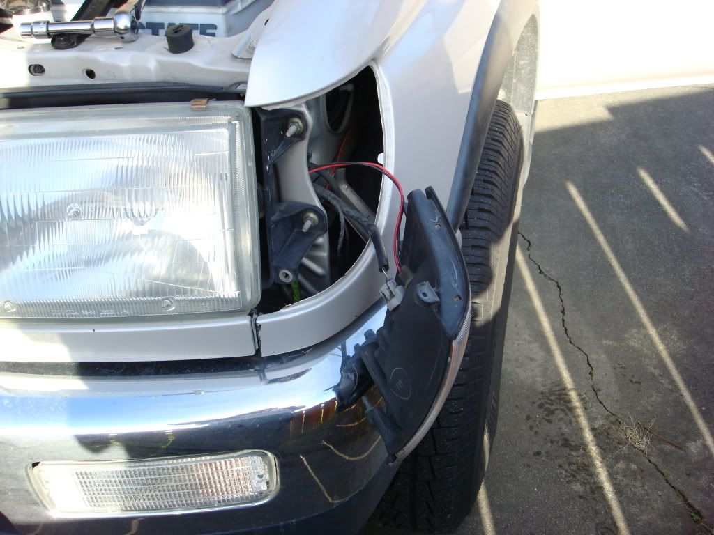
Remove the phillips screw holding the corner light in place.
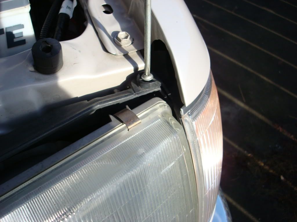
Pull the corner light out of the fender.
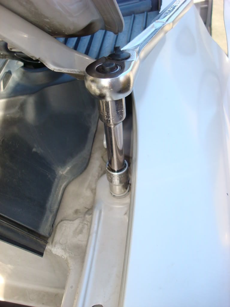
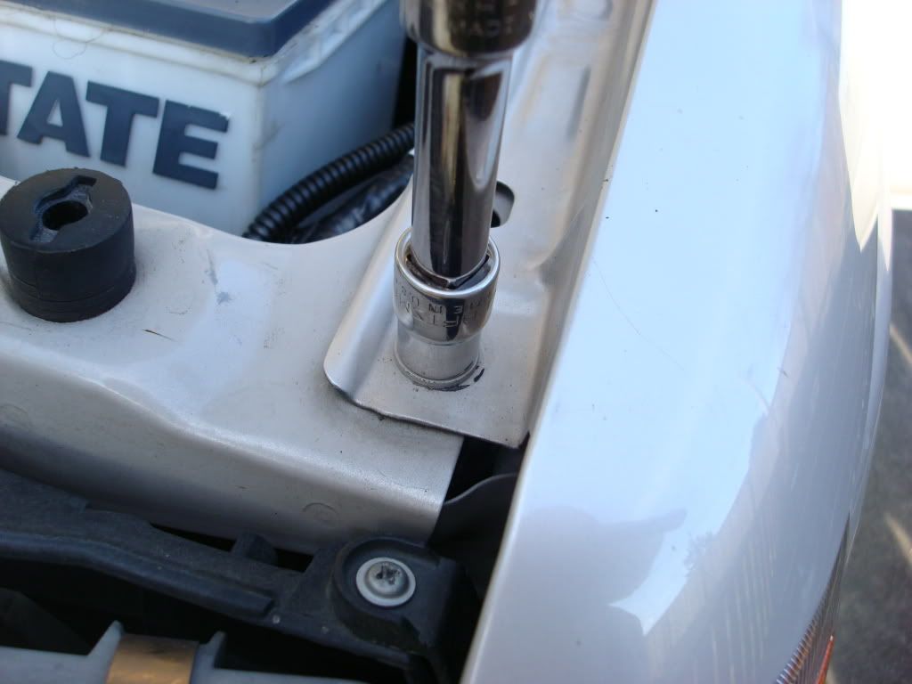
Loosen the retaining bolts securing the fender to the truck body. There are six bolts that we will be removing. Three in the engine compartment, one at the door post and two at the rear base of the fender.
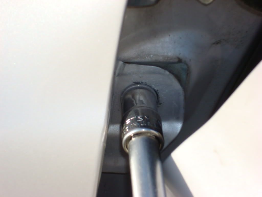
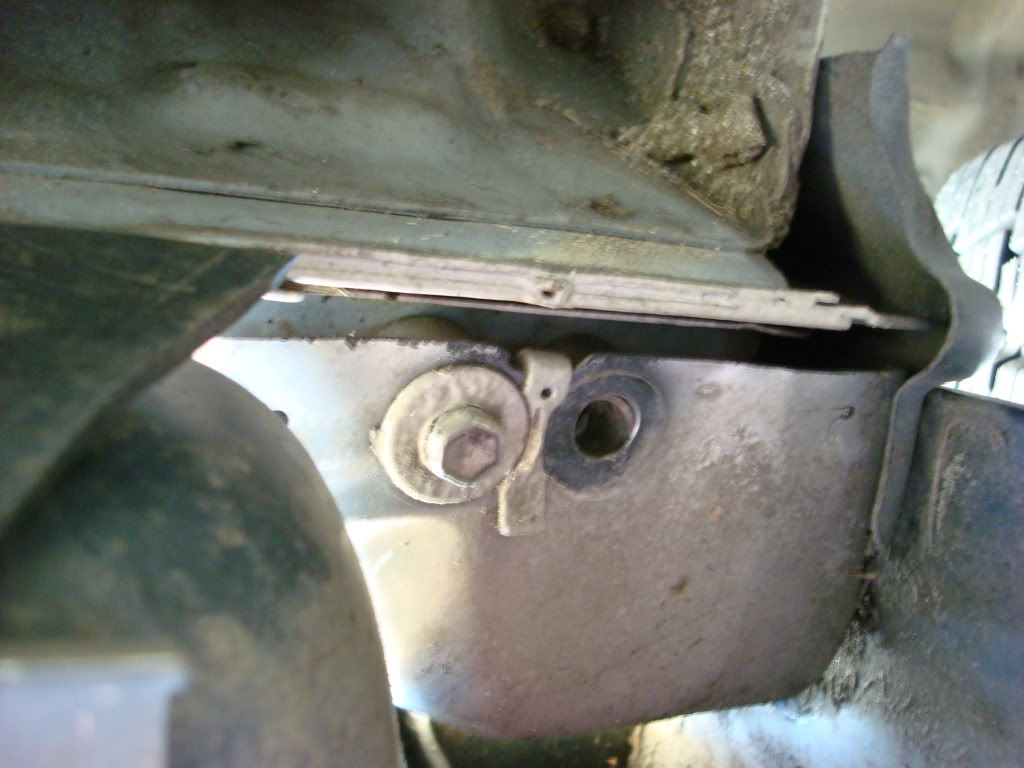
If you have the OEM running boards installed you will need to remove two nuts securing the front corner of the running board to allow for easy access to the two lower fender nuts.
The fender will only need to be partially removed in order to be able to get behind the fender to use the TORX bit screwdriver to secure the marker light to the fender. If you desire to completely remove the fender, you will need to remove the front bumper as well in order to get to the front fender mounting screw.
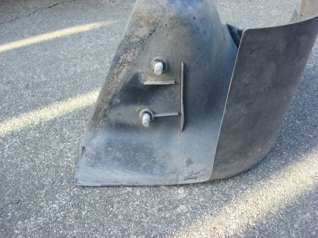
Next the fender inner skirt will need to be loosened. This will entail removal of the fender
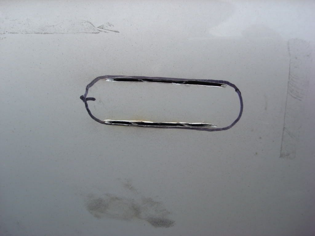
Using a Dremel tool with heavy duty cut off wheels, cut the straight portion of the lines just to the edge where the outline starts to curve.
I had to drill out the area in the curves as I did not have a drill or knock out punch that would speed this process up.
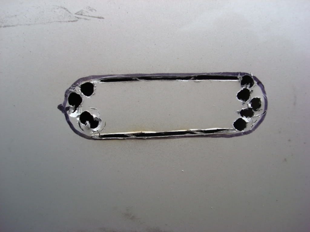
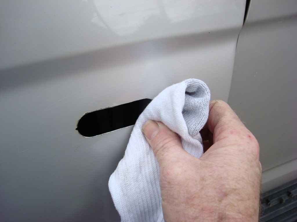
Next remove the cutout from the fender. You will now be ready for trim and fitting.
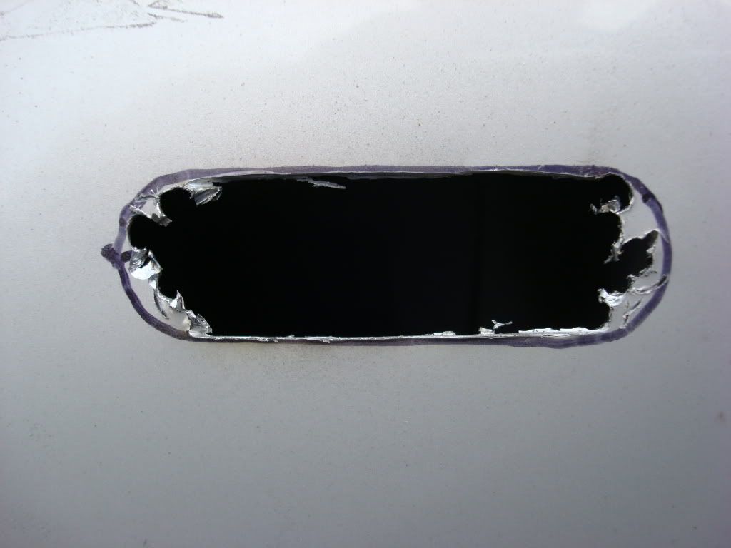
Begin with rough sizing the hole. I used Dremel grinding stones vice sanding drums. They cost about $2 each. It will last longer and I found better control with the stones. Take your time, this is not a race!
Continue sizing the hole until you are almost to the edge of your markings. Use the lamp assembly to check for fitment.
Do not force the lamp assembly into the hole. Repeat the prefitting until the lamp assembly will slide in but not be loose fit.
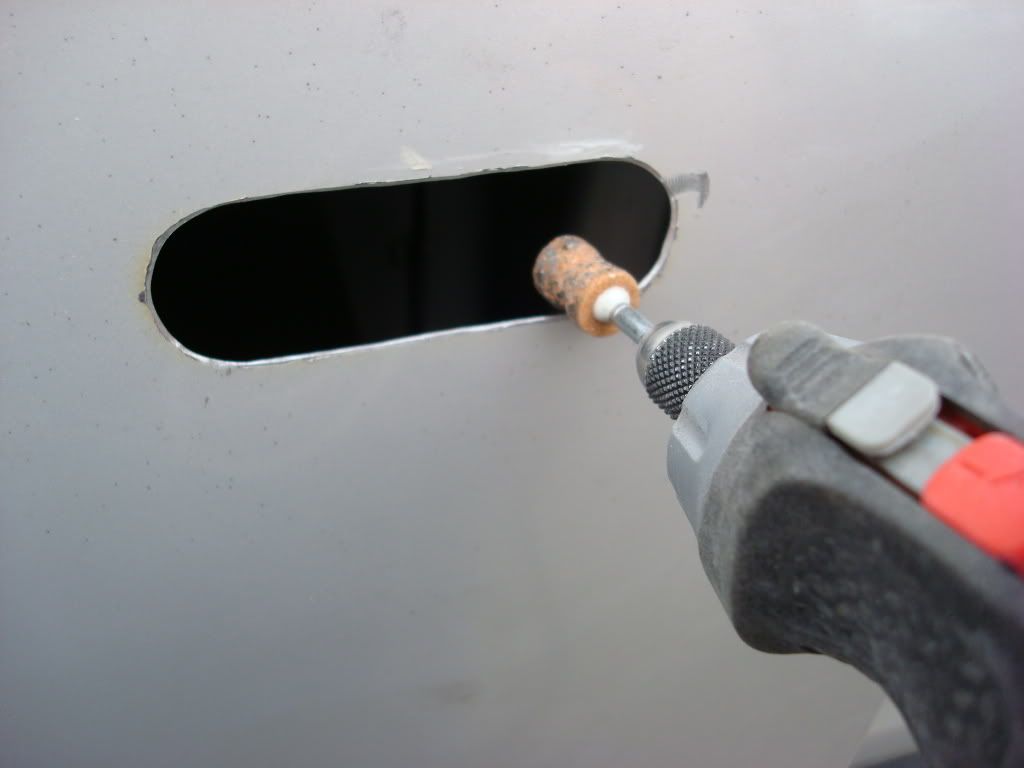
Once the hole has been sized, sand the hole edges to remove any burrs or sharp edges. I used the sanding drum for this. Angle the drum along the inside and outside edges to round the cutout.
[IMG]http://i207.photobucket.com/albums/bb56/_ritz_/Side%20Markers/Sidemarker021.
jpg[/IMG]
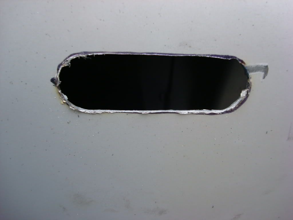
Once the hole has been completed, clean the edges with rubbing alcohol. This will prep the edges for priming and remove any loose debris.
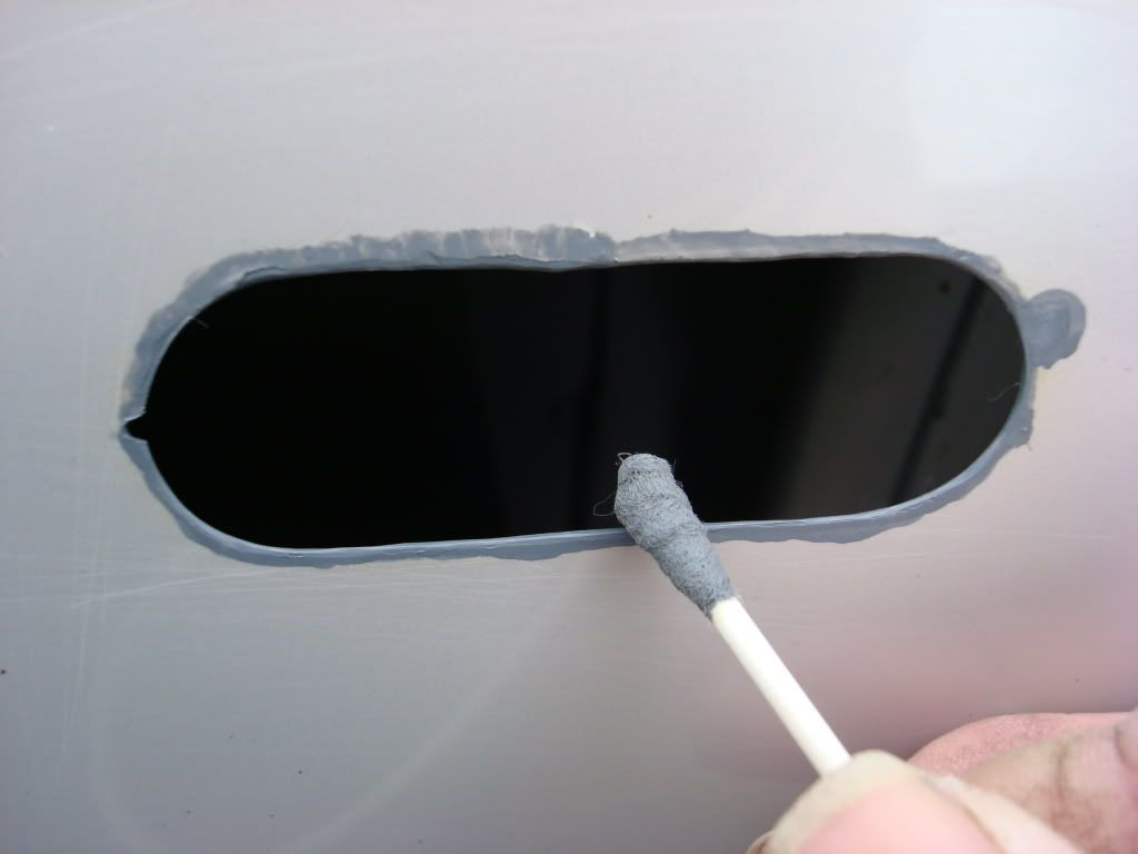
Any quality auto primer will work very nicely for this step. Use a plastic cap from any sort of container and spray some primer into it. Using a Q-tip, dip the end in the primer then roll the Q-tip along the edge of the cut out. Be sure to keep the tip wet with paint. Roll the tip along the inside edge and then the outer edge. You may need to dap some spots to get complete coverage. It is important to be sure you seal the entire edge so that you will not have any place for rust to begin. You may notice that I had a bit of a �tail� near the end of the hole, this was from a drill bit that tried to run on me. I primed it and the edge of the marker covered it.
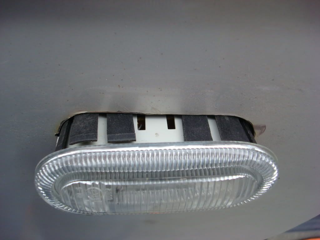
Remove the connector from the lamp assembly. Verify you have the rubber gasket installed on the lamp assembly. Insert the lamp assembly into your prepared and dry cut out. Secure the assembly from inside the fender using the two #20 TORX screws on the assembly bracket. Do not over tighten these screws. Just get them snug.
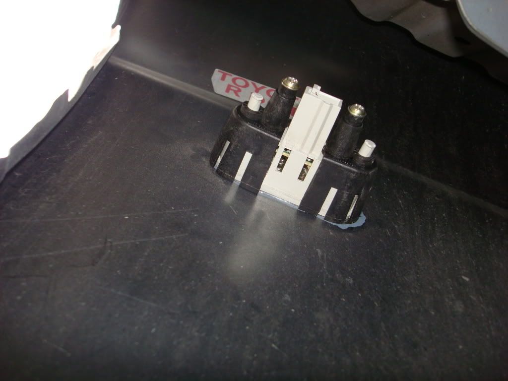
Remember that the lamp assembly has a small ridge on the forward end of the assembly. You must ensure that this ridge is facing FORWARD when installed in the fender. The zing-zag reflector will be to the rear of the fender.
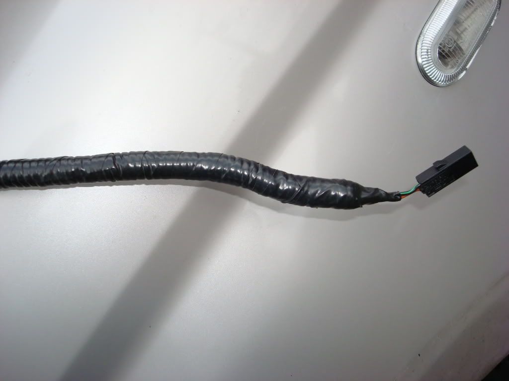
Depending on how much of the OEM connector wiring you have will determine how much wire you will need to route from the connector to the front turn signal wires. I tried to use automotive wire that were either the same color or close to the same color as the OEM wires on the truck. If you want a truly finished wire harness, strip and solder the wires from the connector to your extended wires and then shrink wrap the exposed areas.
I also picked up some split loom at the wrecking yard in the small size approximately � inch. You can get quite handful for around $1. Auto supply stores carry it but its normally �� and larger. Insert the wires into the split loom and using electrical tape, tape the ends of the split loom to the connector then work your way towards the ends you will splice into the turn signal wires. You don�t need to wrap the entire length of the new harness just enough of the loom until it would enter the engine compartment. This will help to keep water and mud from getting into the loom and wires.
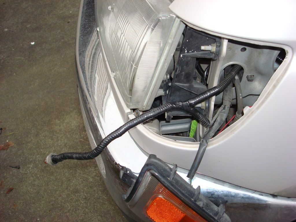
Next, stretch out the wire from the lamp assembly to the front bumper. This will be about the length you will need. Route the harness from the lamp assembly inside the fender well through the side openings and along the OEM harness run along the top of fender well
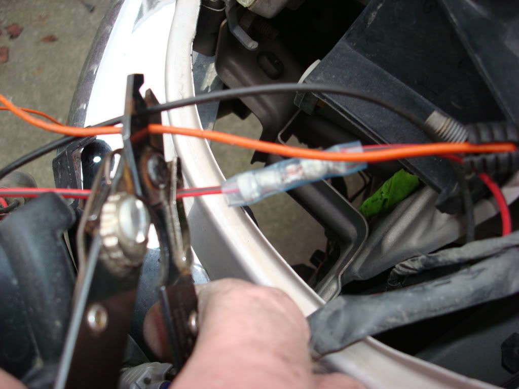
Before you splice the two wires from the lamp assembly to the turn signals, you will need to establish the polarity of the LED lamps. Take each wire from your harness and strip about �� from the ends. Momentarily touch each end of the wires to the + & - terminals of the battery. Only do this for a moment. If the assembly lights, then you know which wire is positive (+) and which is negative(-). Note the color of each wire to its polarity. It is imperative that you connect these correctly as if they are reversed the LED will not light.
The wires for the turn signals are as follows:
Left :
Green/Black +
White/Black �
Right:
Green/Yellow +
White/Black �
NOTE: I installed blinkers in my corner lights ( https://www.yotatech.com/forums/f127.../#post50701639 )so it made it simple to splice into my turn signal wires. The following pictures will show the splicing of the side marker into these wires so the color of your wires may be different then those displayed below. The directions are for the above listed OEM turn signal wires.
Determine which of the wires are positive(+) and negative(-) and splice them accordingly. Remember that the OEM turn signal positive (+) wires are green/black and green/yellow. White black are ground (-) on both sides of the vehicle.
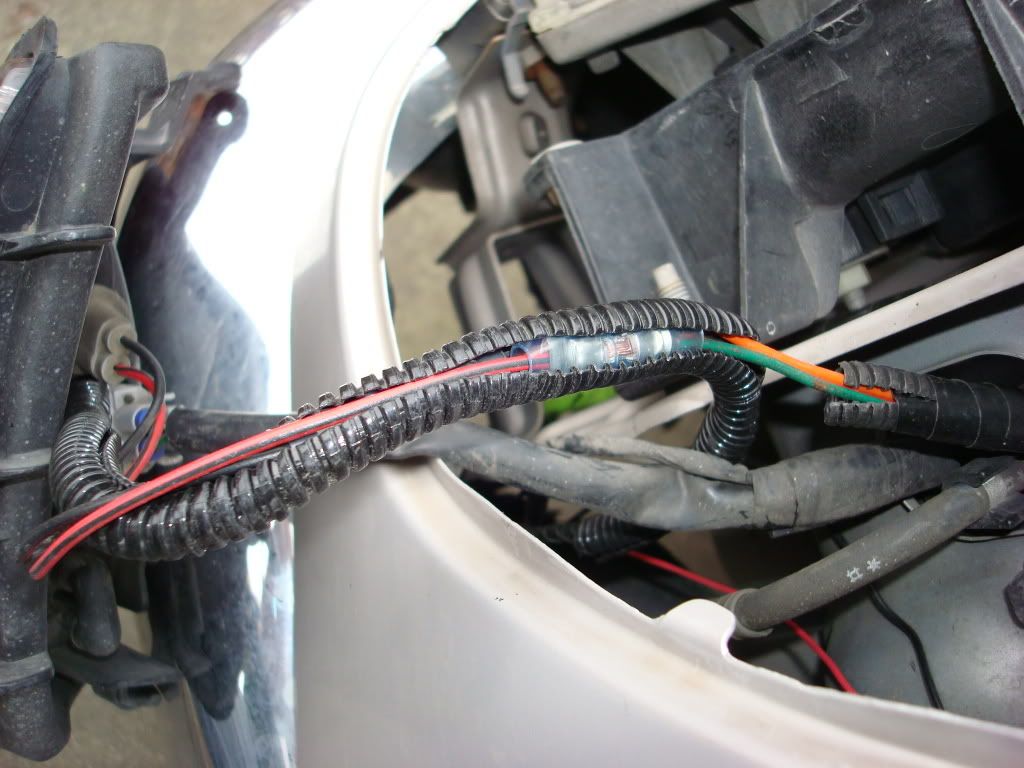
Next using some more split loom, I inserted the wires into the loom and taped them making a finished harness that will be protected from the elements.
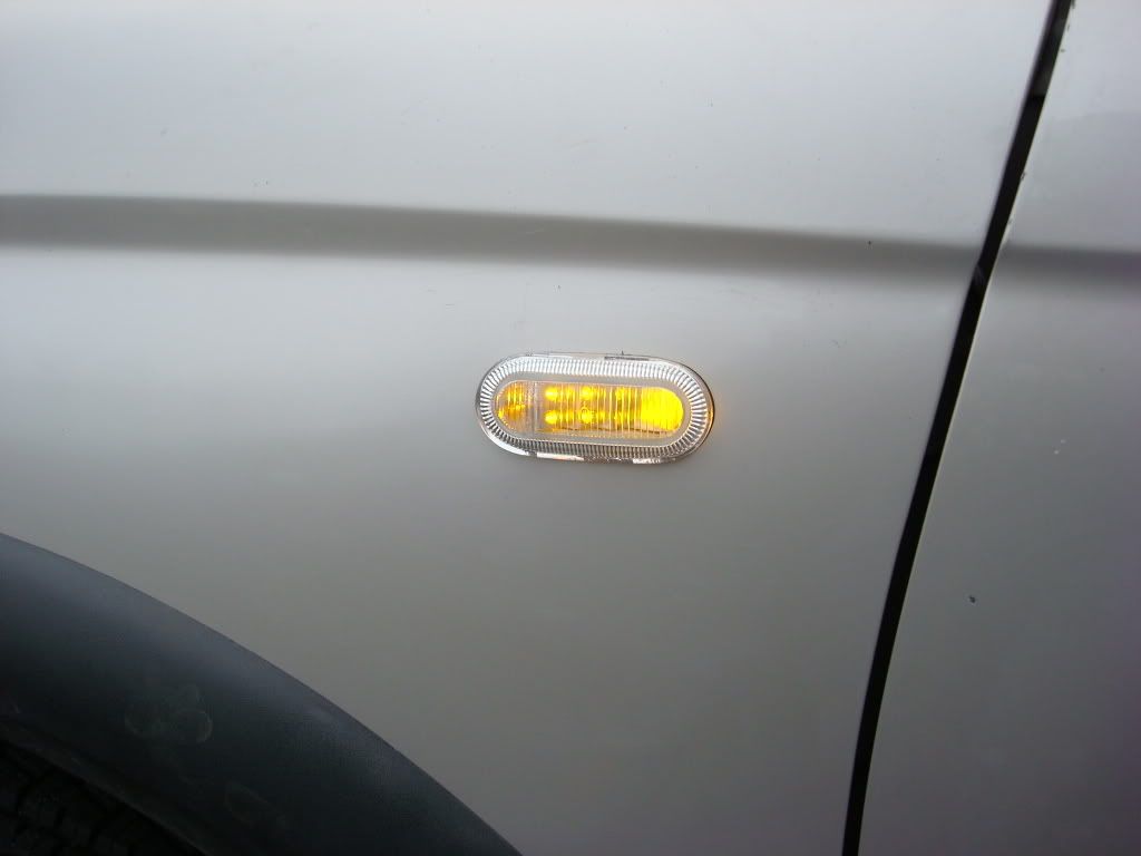
If you removed the wires from the turn signals as I did, reattach the connectors, install the lamps/corner lights and test the signals for operation.
The right side will be almost identical to the left but you will have to deal with the radio antenna. I have not completed this install on the right side as of this writing as I need some warmer weather to finish this up. I will take pictures of my install on the right and will incorporate those into the write up when completed. Good luck and if you have any questions or comments, I welcome them.
NOTE:
Disclaimer: This modification is not part of any OEM application and as such carries no warranty of any kind. Any modification to your vehicle using these recommendations contained within this article is at the owner/operator/installers own risk. While I have performed this installation on my own vehicle each vehicle may be different depending on year and options. Please read all instruction before proceeding. Remember you do so at your own risk.
There are several quality side marker on many of the newer vehicles out there. Some now are LED as well as incandescent. I chose to use the newer LED side markers. These are found on many of the later "new" style VW Beetles. You can order/purchase form most any VW dealer. The lamp fixtures themselves are just under $43 each and then you have to procure the cable ends. These may be a bit more difficult to locate as these are the ends that are part of the cable harness and plug into the marker socket.
I located mine in a local wrecking yard. Cost will be abut � or even less. One important factor to remember when you try to remove these from a wrecked vehicle, it will require a #20 TORX bit screw driver and you need to get to the back side of the marker. On the VW it is extremely difficult to remove these unless the dash has been removed or the fenders have been loosened or pulled. Many yards prefer that you do not remove the markers from good fenders.
To remove the marker from the fender, you need to completely loosen the TORX screws which allows the two piece hold downs to swing inwards towards the connector of the marker. Once loosened the markers can be easily removed and the cable disconnected or cut leaving a useful wire end for splicing.
I started with the left fender. Select the location where you will want to mount the marker lights. Remember that these marker lights are a bit deeper then most other marker lights either from a parts store or from the auto maker.
I would recommend the mounting location I selected as it will be at an excellent height and will clear the interior of the fender when installed. Start from the rear edge of the fender and measure 3 inches. From the top edge of the fender side ridge, measure down 2 inches. This will be your top most edge and rear most edge of the hole you will need to cut into the fender for mounting.
Next you will want to make a template. You can either use a piece of sheet metal such as Bob described or in my case I used a cardboard insert from a Pepsi case. I then used the rubber gasket from the light and drew out the interior of the gasket. Then using the same marker pen re-trace the outline only make the image about 1/8th of an inch larger
Carefully cut out the oval along the outer edge of your line. Place the template on the fender using your reference marks of 2 and 3 inches and secure with tape.
Trace out the oval onto the fender.
You will note that there is a small ridge fin on the marker light to designate which end is towards the front of the vehicle. Mark this as well.
If you would rather remove the fender completely from the vehicle, you will need to remove the bumper to get to the front securing bolt in the fender. This would be the best method of installing these side markers. As I do not have the luxury of leaving my vehicle in a warm dry garage and not needing to drive it for a few days, I opted to do a partial removal.
Next we will need to partially remove the fender so that our TORX screwdriver will be able to be used to install the marker in the finished hole.
Remove the phillips screw holding the corner light in place.
Pull the corner light out of the fender.
Loosen the retaining bolts securing the fender to the truck body. There are six bolts that we will be removing. Three in the engine compartment, one at the door post and two at the rear base of the fender.
If you have the OEM running boards installed you will need to remove two nuts securing the front corner of the running board to allow for easy access to the two lower fender nuts.
The fender will only need to be partially removed in order to be able to get behind the fender to use the TORX bit screwdriver to secure the marker light to the fender. If you desire to completely remove the fender, you will need to remove the front bumper as well in order to get to the front fender mounting screw.
Next the fender inner skirt will need to be loosened. This will entail removal of the fender
Using a Dremel tool with heavy duty cut off wheels, cut the straight portion of the lines just to the edge where the outline starts to curve.
I had to drill out the area in the curves as I did not have a drill or knock out punch that would speed this process up.
Next remove the cutout from the fender. You will now be ready for trim and fitting.
Begin with rough sizing the hole. I used Dremel grinding stones vice sanding drums. They cost about $2 each. It will last longer and I found better control with the stones. Take your time, this is not a race!
Continue sizing the hole until you are almost to the edge of your markings. Use the lamp assembly to check for fitment.
Do not force the lamp assembly into the hole. Repeat the prefitting until the lamp assembly will slide in but not be loose fit.
Once the hole has been sized, sand the hole edges to remove any burrs or sharp edges. I used the sanding drum for this. Angle the drum along the inside and outside edges to round the cutout.
[IMG]http://i207.photobucket.com/albums/bb56/_ritz_/Side%20Markers/Sidemarker021.
jpg[/IMG]
Once the hole has been completed, clean the edges with rubbing alcohol. This will prep the edges for priming and remove any loose debris.
Any quality auto primer will work very nicely for this step. Use a plastic cap from any sort of container and spray some primer into it. Using a Q-tip, dip the end in the primer then roll the Q-tip along the edge of the cut out. Be sure to keep the tip wet with paint. Roll the tip along the inside edge and then the outer edge. You may need to dap some spots to get complete coverage. It is important to be sure you seal the entire edge so that you will not have any place for rust to begin. You may notice that I had a bit of a �tail� near the end of the hole, this was from a drill bit that tried to run on me. I primed it and the edge of the marker covered it.
Remove the connector from the lamp assembly. Verify you have the rubber gasket installed on the lamp assembly. Insert the lamp assembly into your prepared and dry cut out. Secure the assembly from inside the fender using the two #20 TORX screws on the assembly bracket. Do not over tighten these screws. Just get them snug.
Remember that the lamp assembly has a small ridge on the forward end of the assembly. You must ensure that this ridge is facing FORWARD when installed in the fender. The zing-zag reflector will be to the rear of the fender.
Depending on how much of the OEM connector wiring you have will determine how much wire you will need to route from the connector to the front turn signal wires. I tried to use automotive wire that were either the same color or close to the same color as the OEM wires on the truck. If you want a truly finished wire harness, strip and solder the wires from the connector to your extended wires and then shrink wrap the exposed areas.
I also picked up some split loom at the wrecking yard in the small size approximately � inch. You can get quite handful for around $1. Auto supply stores carry it but its normally �� and larger. Insert the wires into the split loom and using electrical tape, tape the ends of the split loom to the connector then work your way towards the ends you will splice into the turn signal wires. You don�t need to wrap the entire length of the new harness just enough of the loom until it would enter the engine compartment. This will help to keep water and mud from getting into the loom and wires.
Next, stretch out the wire from the lamp assembly to the front bumper. This will be about the length you will need. Route the harness from the lamp assembly inside the fender well through the side openings and along the OEM harness run along the top of fender well
Before you splice the two wires from the lamp assembly to the turn signals, you will need to establish the polarity of the LED lamps. Take each wire from your harness and strip about �� from the ends. Momentarily touch each end of the wires to the + & - terminals of the battery. Only do this for a moment. If the assembly lights, then you know which wire is positive (+) and which is negative(-). Note the color of each wire to its polarity. It is imperative that you connect these correctly as if they are reversed the LED will not light.
The wires for the turn signals are as follows:
Left :
Green/Black +
White/Black �
Right:
Green/Yellow +
White/Black �
NOTE: I installed blinkers in my corner lights ( https://www.yotatech.com/forums/f127.../#post50701639 )so it made it simple to splice into my turn signal wires. The following pictures will show the splicing of the side marker into these wires so the color of your wires may be different then those displayed below. The directions are for the above listed OEM turn signal wires.
Determine which of the wires are positive(+) and negative(-) and splice them accordingly. Remember that the OEM turn signal positive (+) wires are green/black and green/yellow. White black are ground (-) on both sides of the vehicle.
Next using some more split loom, I inserted the wires into the loom and taped them making a finished harness that will be protected from the elements.
If you removed the wires from the turn signals as I did, reattach the connectors, install the lamps/corner lights and test the signals for operation.
The right side will be almost identical to the left but you will have to deal with the radio antenna. I have not completed this install on the right side as of this writing as I need some warmer weather to finish this up. I will take pictures of my install on the right and will incorporate those into the write up when completed. Good luck and if you have any questions or comments, I welcome them.


Thread
Thread Starter
Forum
Replies
Last Post
ashersullivan88yota
86-95 Trucks & 4Runners
24
01-18-2022 05:37 PM
GreatLakesGuy
The Classifieds GraveYard
8
09-04-2015 09:27 AM
Johntom240
General Electrical & Lighting Related Topics
7
07-13-2015 12:18 AM


