
W56 Top Shift Rebuild With Marlins Kit - Pics Along the Way
 08-28-2012, 10:38 PM
#41

I have some more progress to post up. Here is the next set that is getting ready to be pressed on. This is probably the most troublesome part of the whole project, taking it on and off. I had to make a custom plate and then reinforce it with additional steel because it was bending when i was pulling the gear/bearing on.

 08-28-2012, 10:45 PM
#43
This is how you put one of the hub assemblies together.
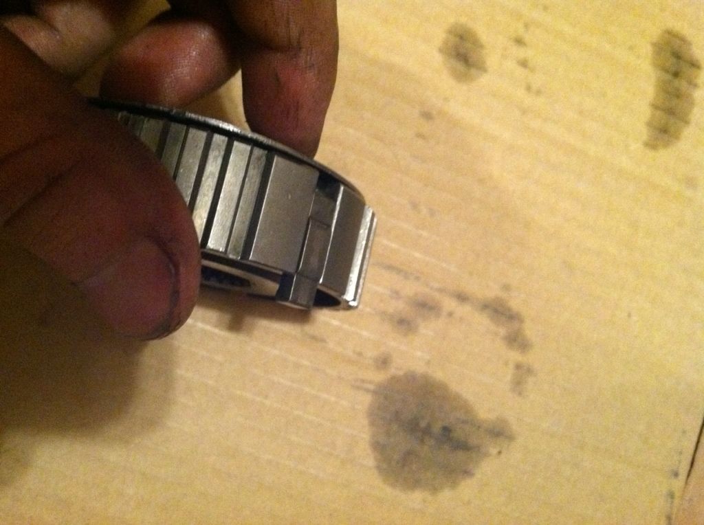
Snap ring that need to be in both sides before you do anything else:
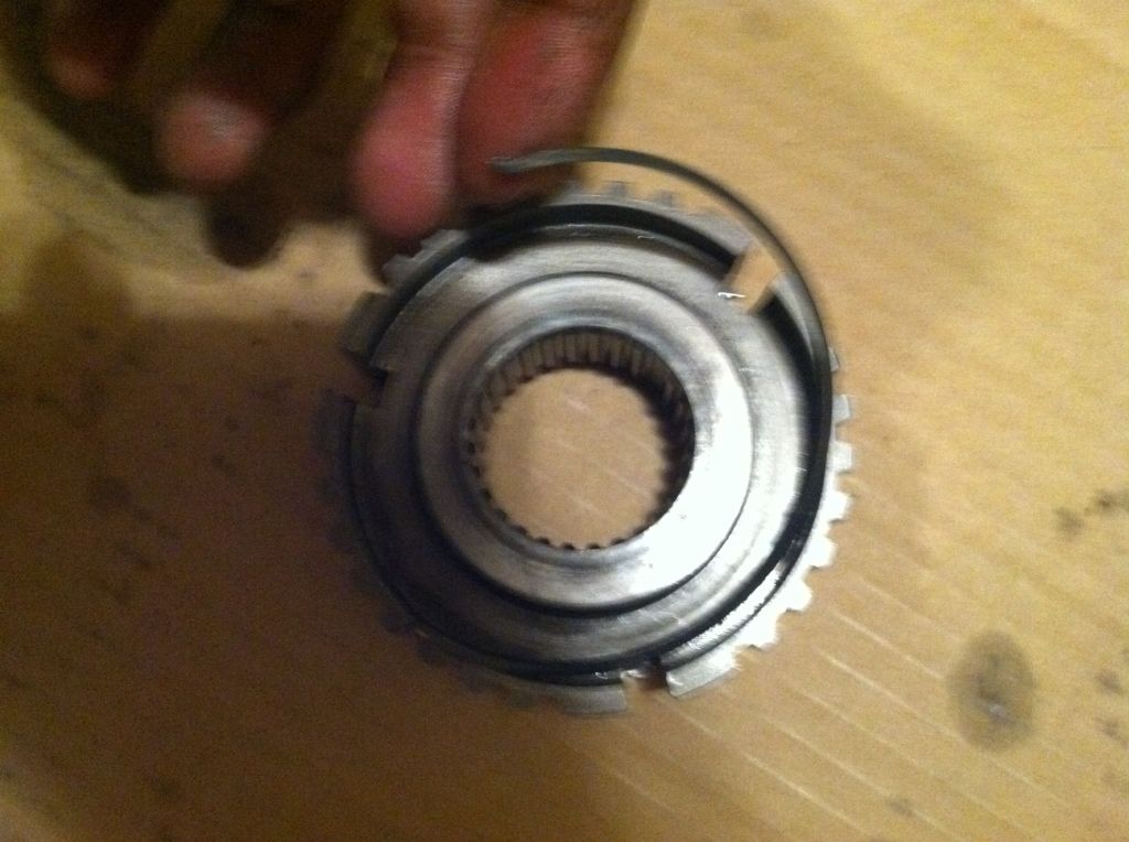
This particular gear hub has the clip already in the back that stays there, this pic is just showing it.
Another pic:
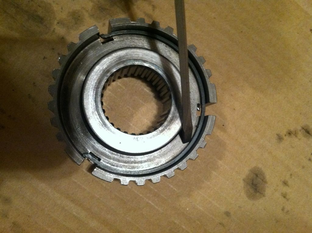
Here you can see the slots that the keys go into. Notice which way the key is, they all need to face that same direction:
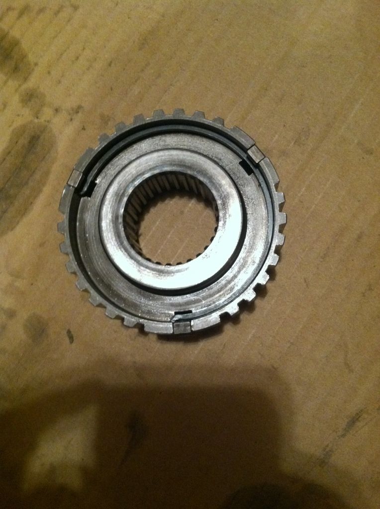
All of the keys in place
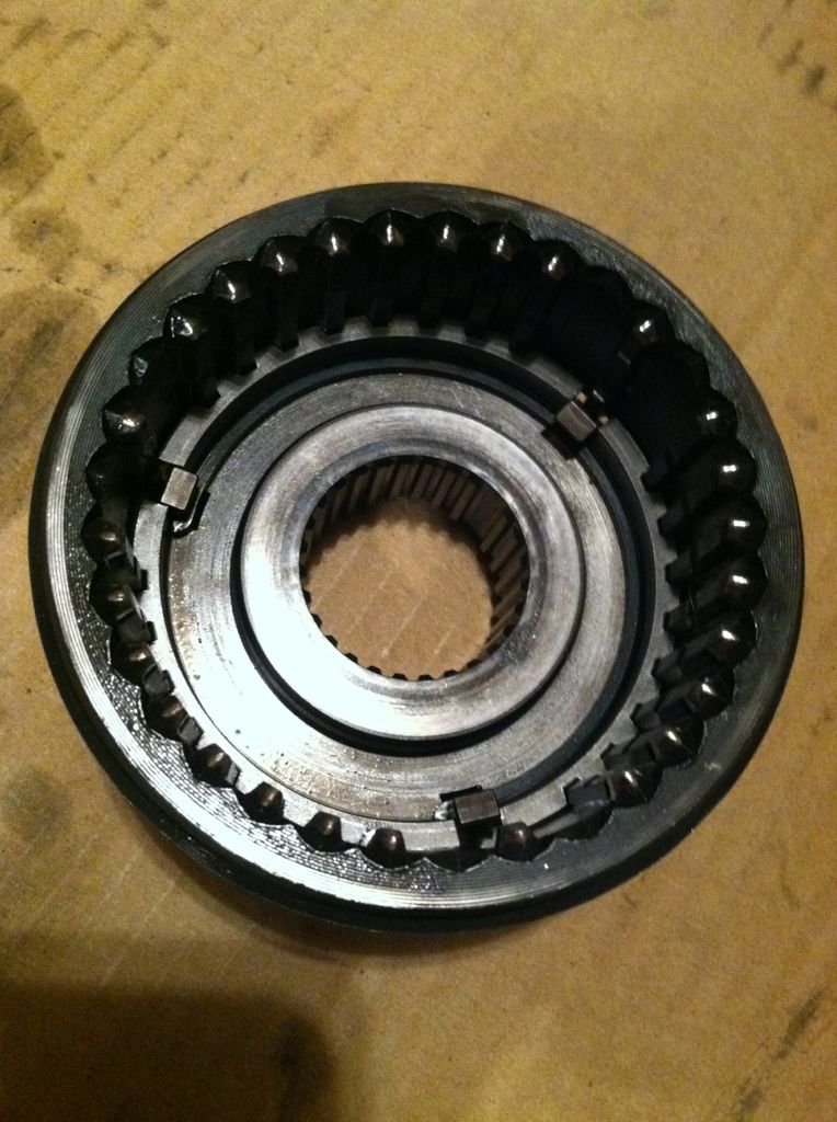
Outer ring that shift fork goes on in place. It pretty much just presses down and will "snap" into place over the hub.
Snap ring that need to be in both sides before you do anything else:
This particular gear hub has the clip already in the back that stays there, this pic is just showing it.
Another pic:
Here you can see the slots that the keys go into. Notice which way the key is, they all need to face that same direction:
All of the keys in place
Outer ring that shift fork goes on in place. It pretty much just presses down and will "snap" into place over the hub.
08-28-2012, 10:51 PM
#44
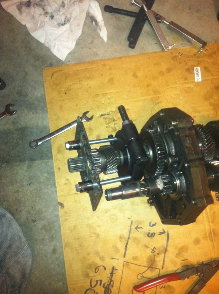
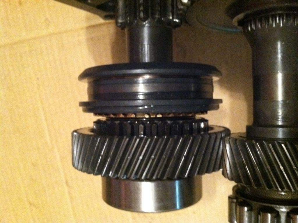
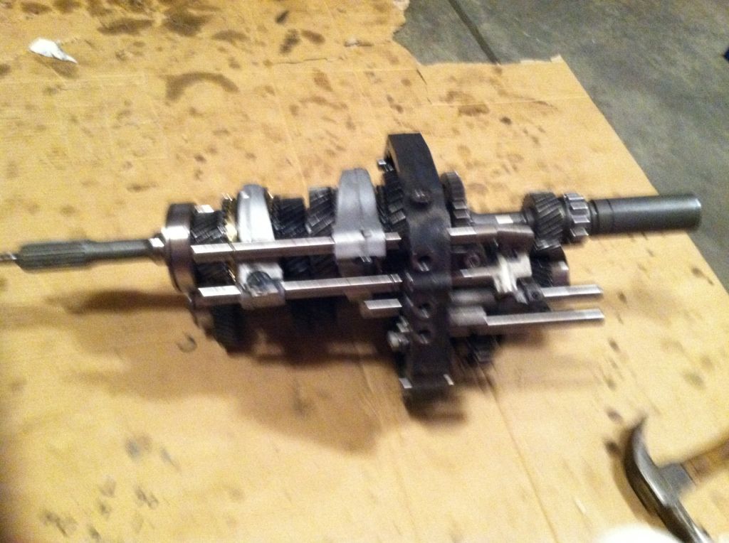
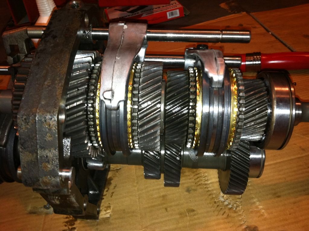
Assembly before pressed on:
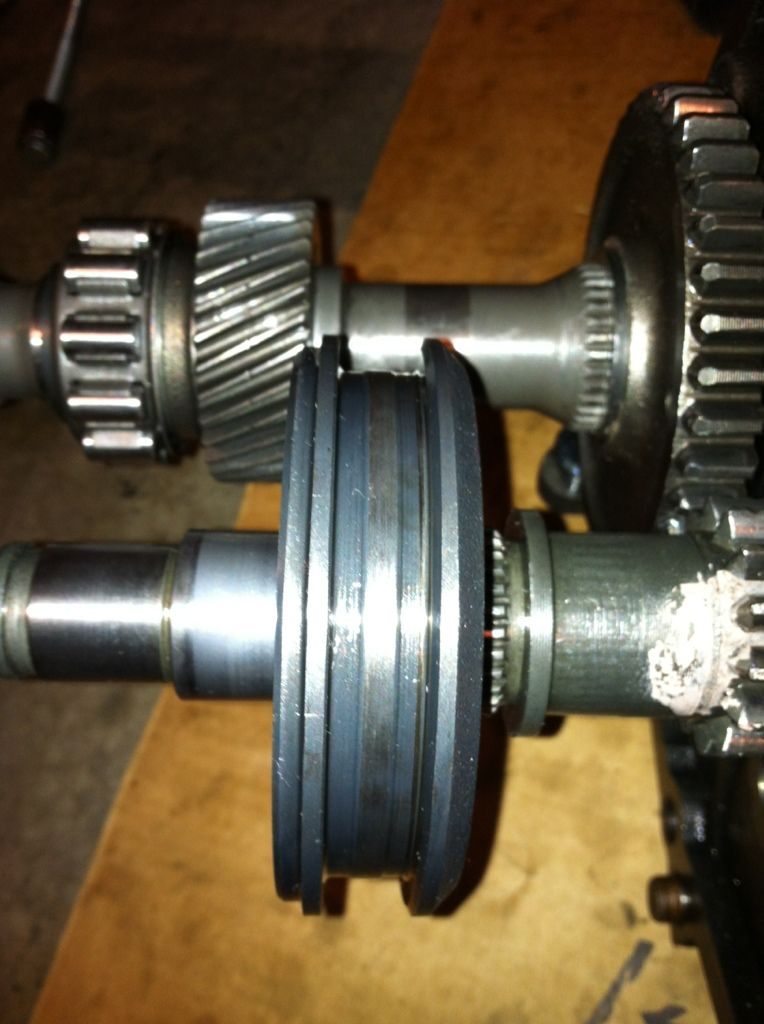
This is how I propped the assembly so that the counter shaft took the brunt of the hits to pound the assembly in place. The FSM recommended placing an equivalently heavy hammer on the other end of the counter shaft. I figured this was just as good and was sure that the shaft was taking the trauma and not the bearing on the end (it is close). Also be sure that the counter shaft is pushing into anything else on the main shaft because it may mess up your thrust clearances that you measured earlier in the assembly process on the main shaft.
This is how I propped the assembly so that the counter shaft took the brunt of the hits to pound the assembly in place. The FSM recommended placing an equivalently heavy hammer on the other end of the counter shaft. I figured this was just as good and was sure that the shaft was taking the trauma and not the bearing on the end (it is close). Also be sure that the counter shaft is pushing into anything else on the main shaft because it may mess up your thrust clearances that you measured earlier in the assembly process on the main shaft.
08-28-2012, 10:52 PM
#45
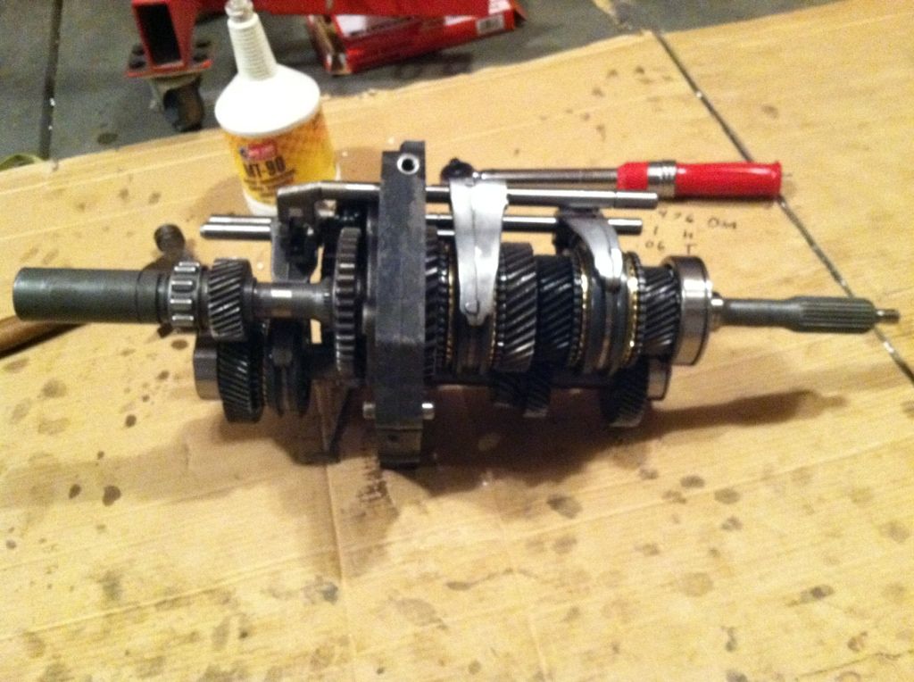
Here it is with the snap ring. There is also a small spacer ring that goes on, as seen in the photo. DON'T FORGET THIS
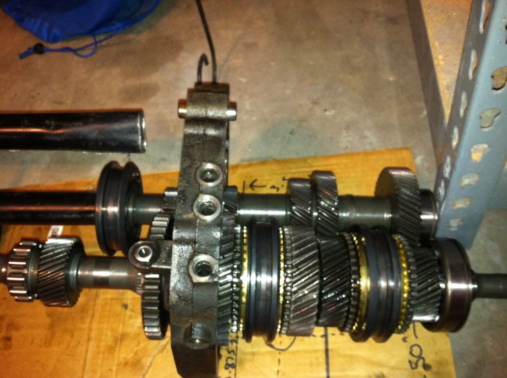
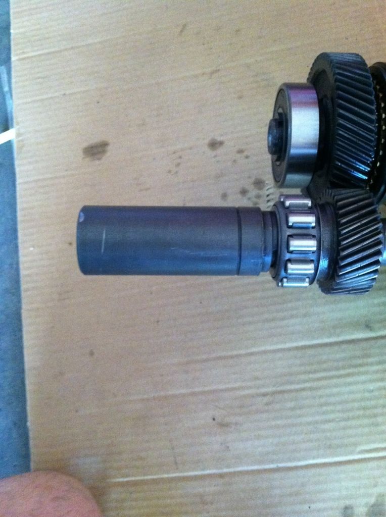
Here is the rest of the shaft components installed for that shaft. My phone died during this, so I couldn't get as many pics.
There is the small spacer ring as shown above, then the gear/hub assembly, then another spacer that must be "pressed" on (used a 22 metric socket at this point). I tapped that on until it hit the gear that was on just before it. Then I put the bearing on (my bearing was covered/sealed on both sides
Last edited by live4soccer7; 08-28-2012 at 11:01 PM.
08-29-2012, 11:26 PM
#46
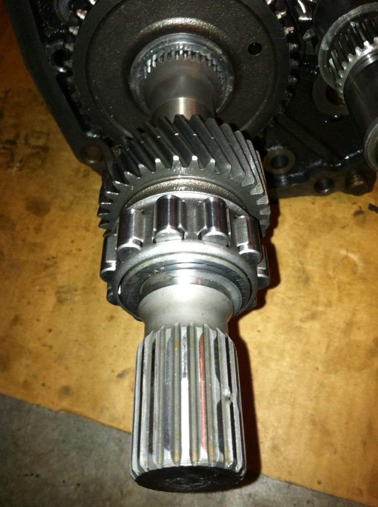
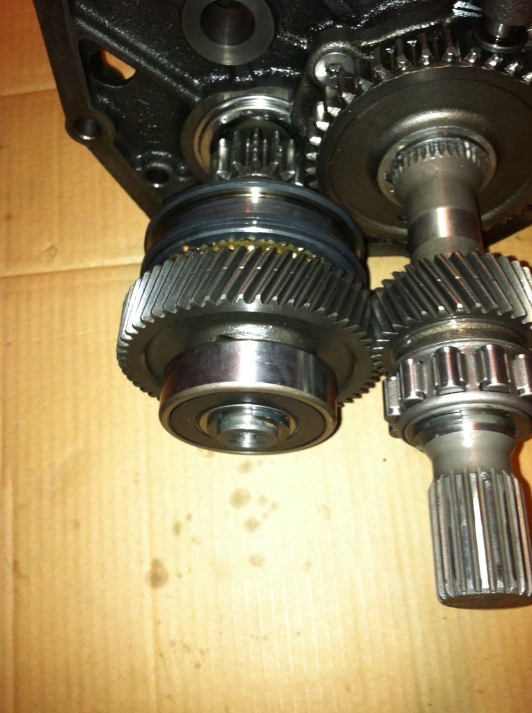
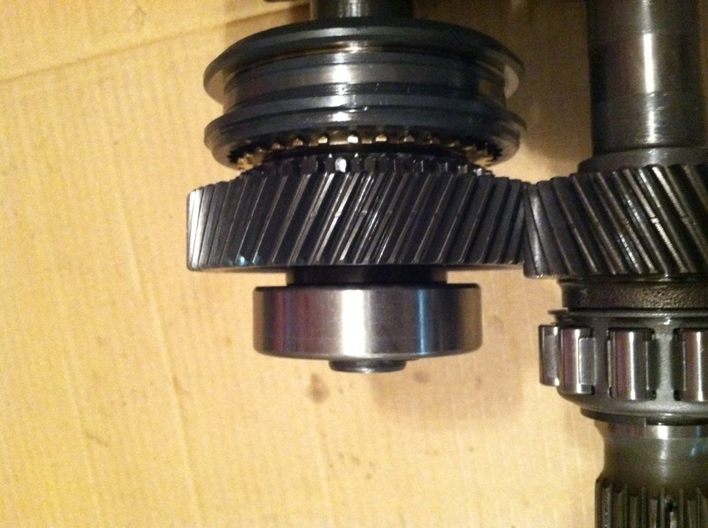
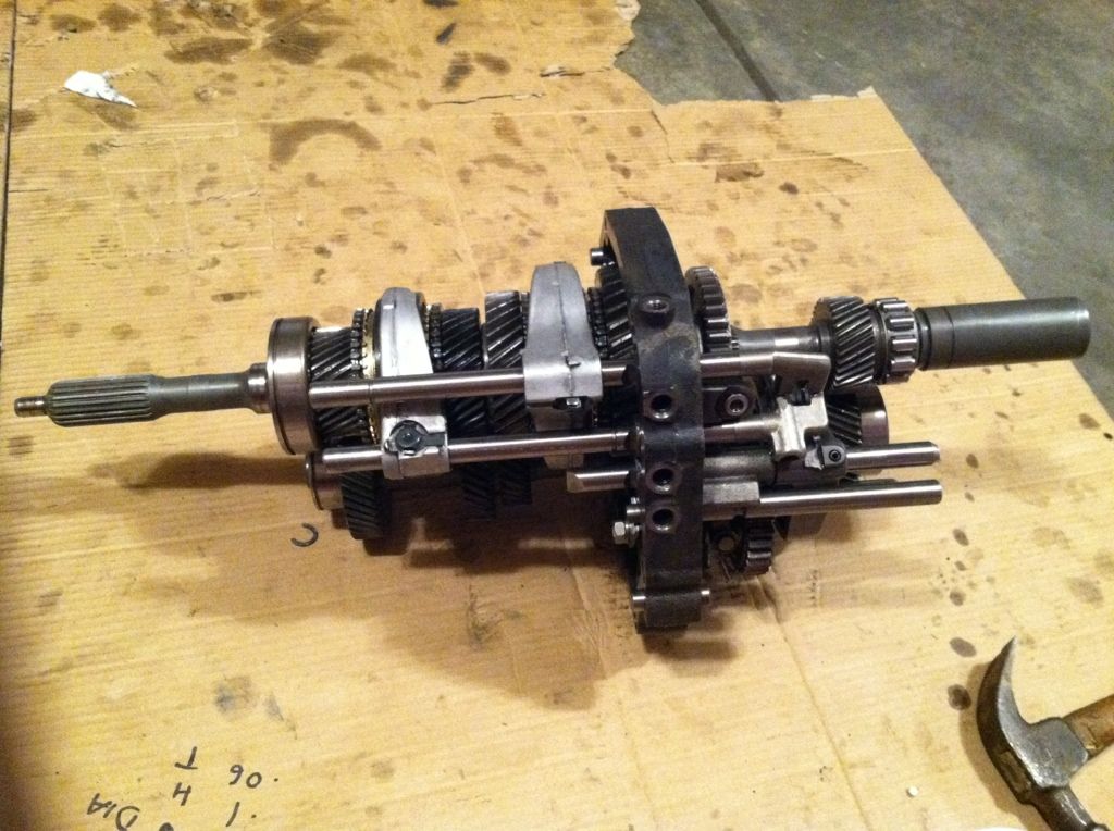
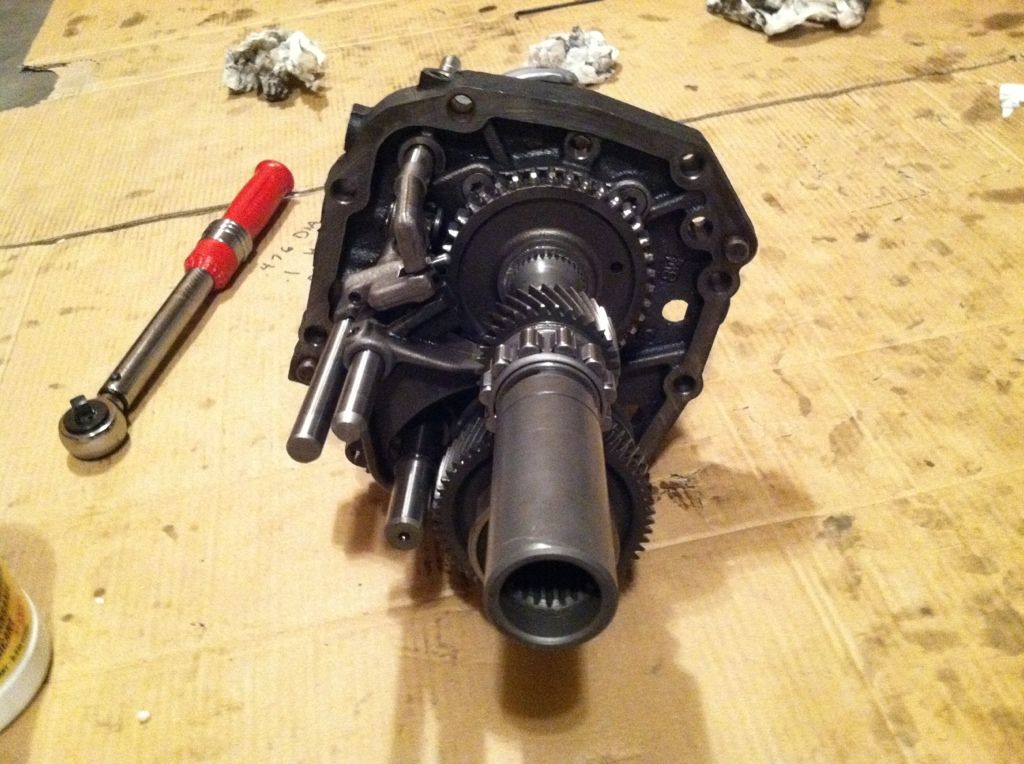
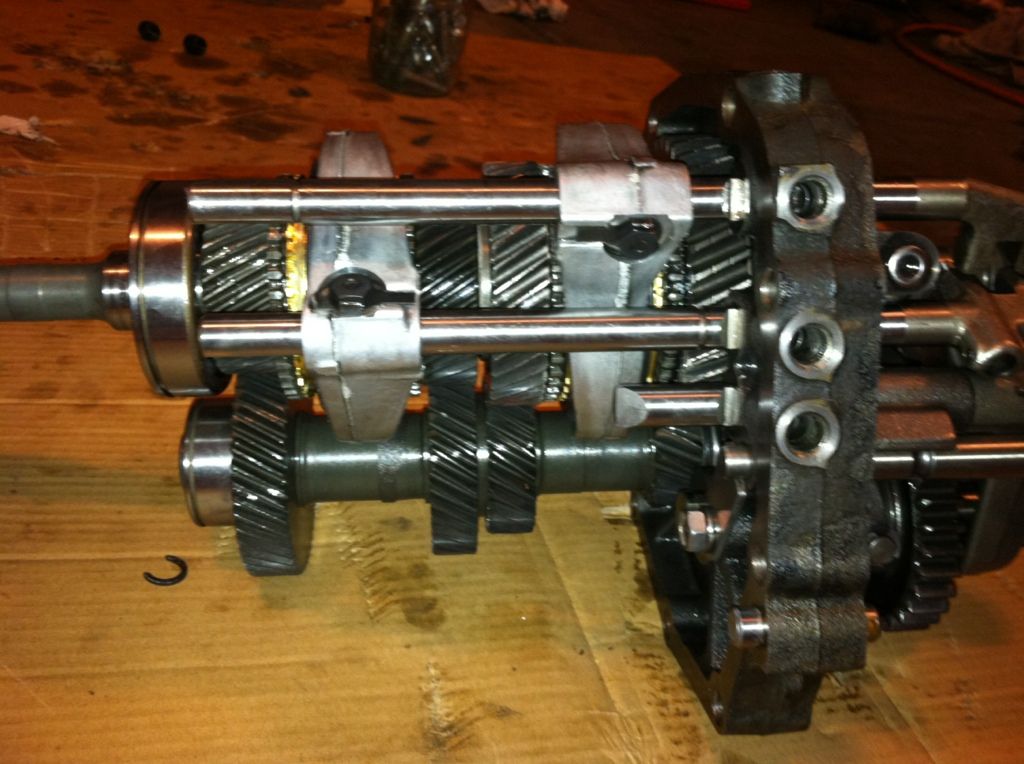
Here is the output sleeve installed on the shaft. It was much easier than I anticipated. I lined up the splines and then held the gear right in front of it and hit it with a sledgehammer. Went right on after many hits. I didn't even see this sleeve in the FSM.
08-29-2012, 11:28 PM
#47
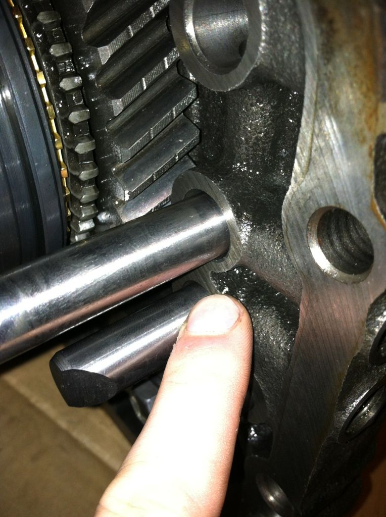
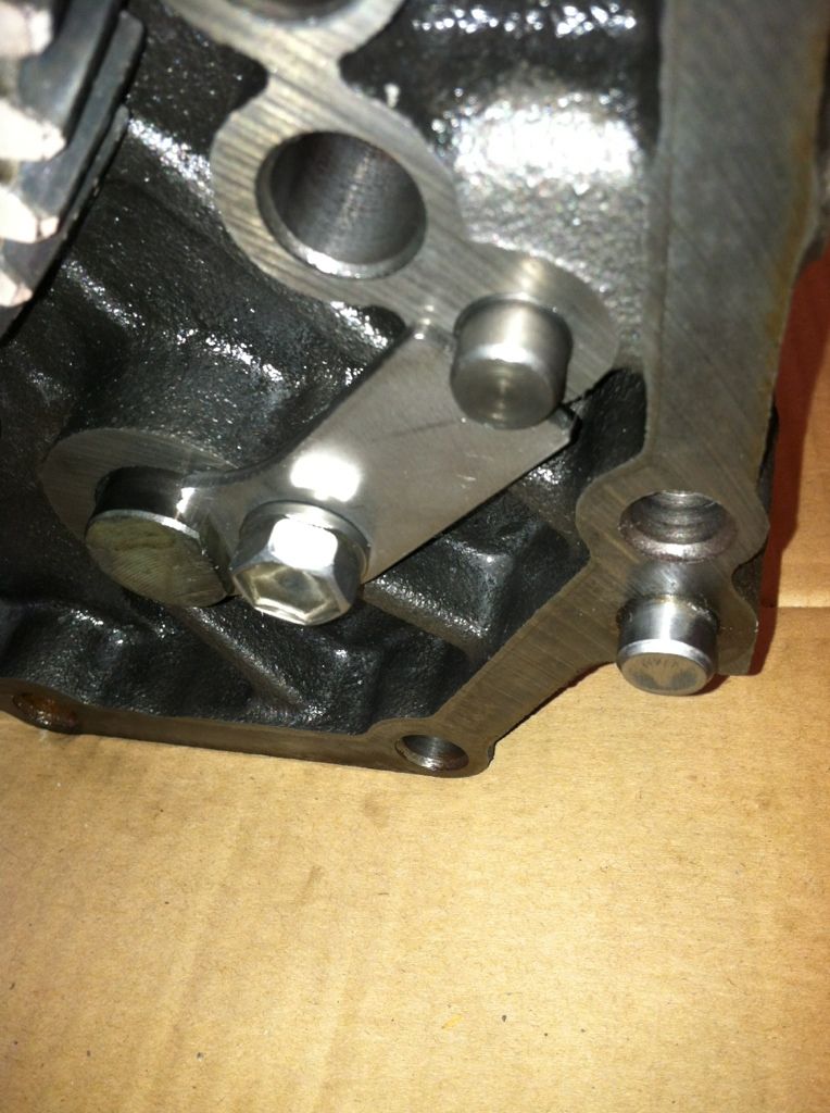
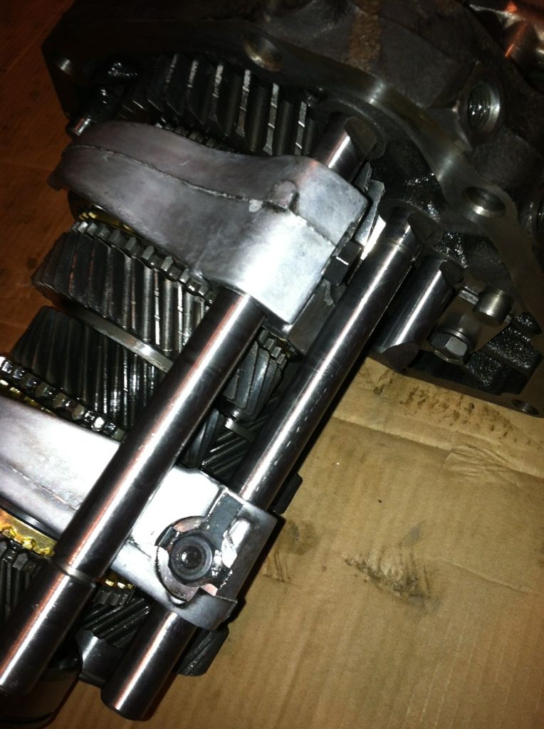
I am pointing to where the middle length pin of the three that have the same diameter (4 total from the w56). I will see if I have a picture of all of them, but I'm not sure if I do.
 08-29-2012, 11:30 PM
#49
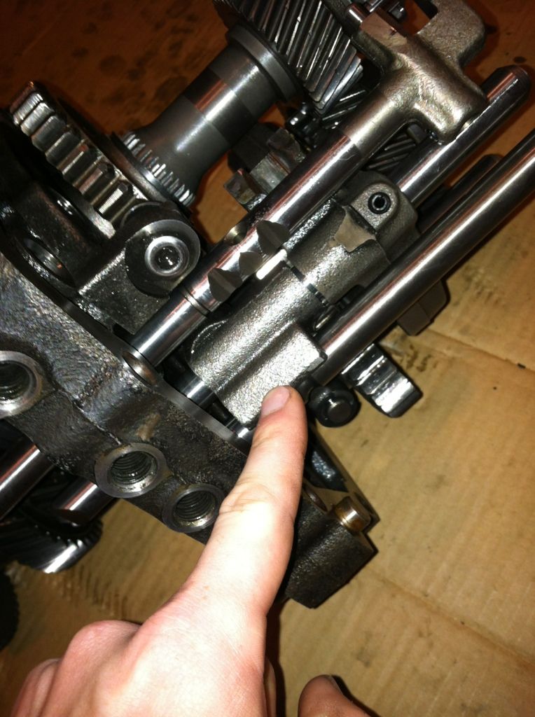
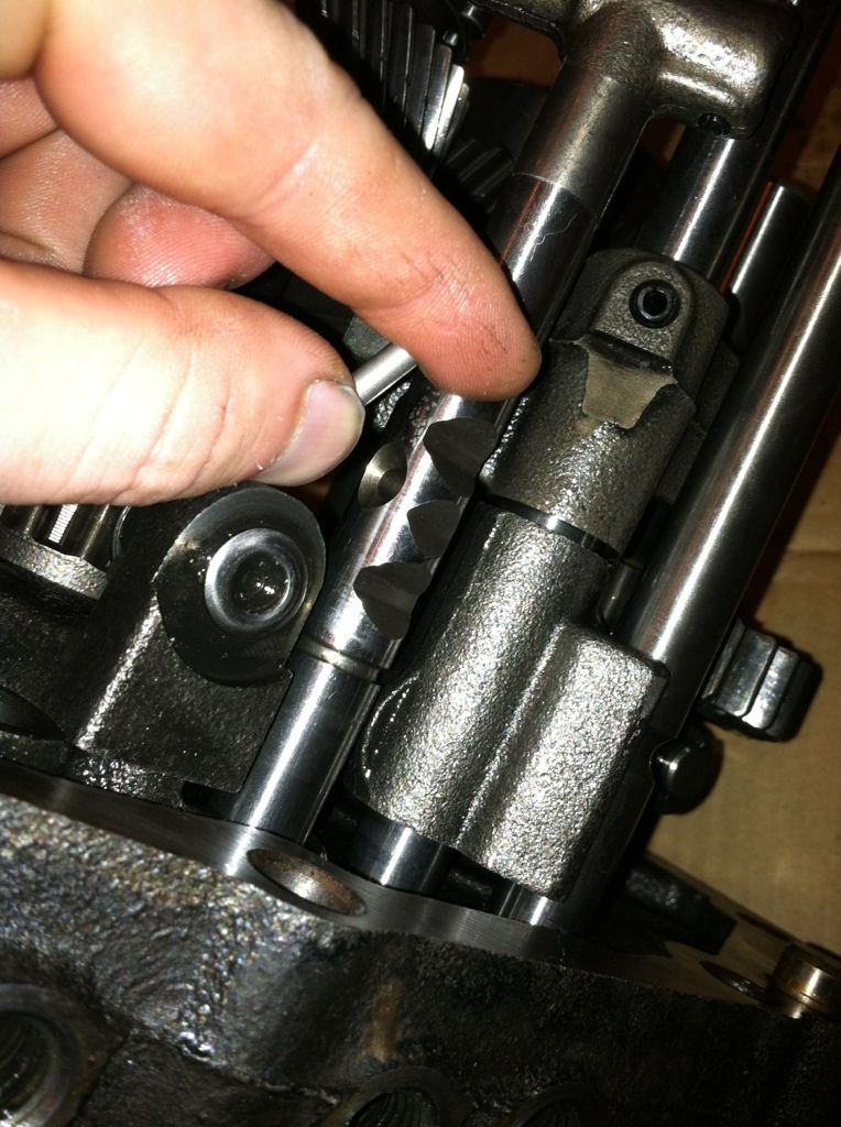
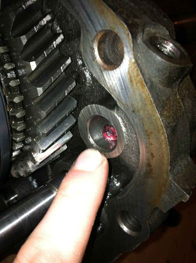
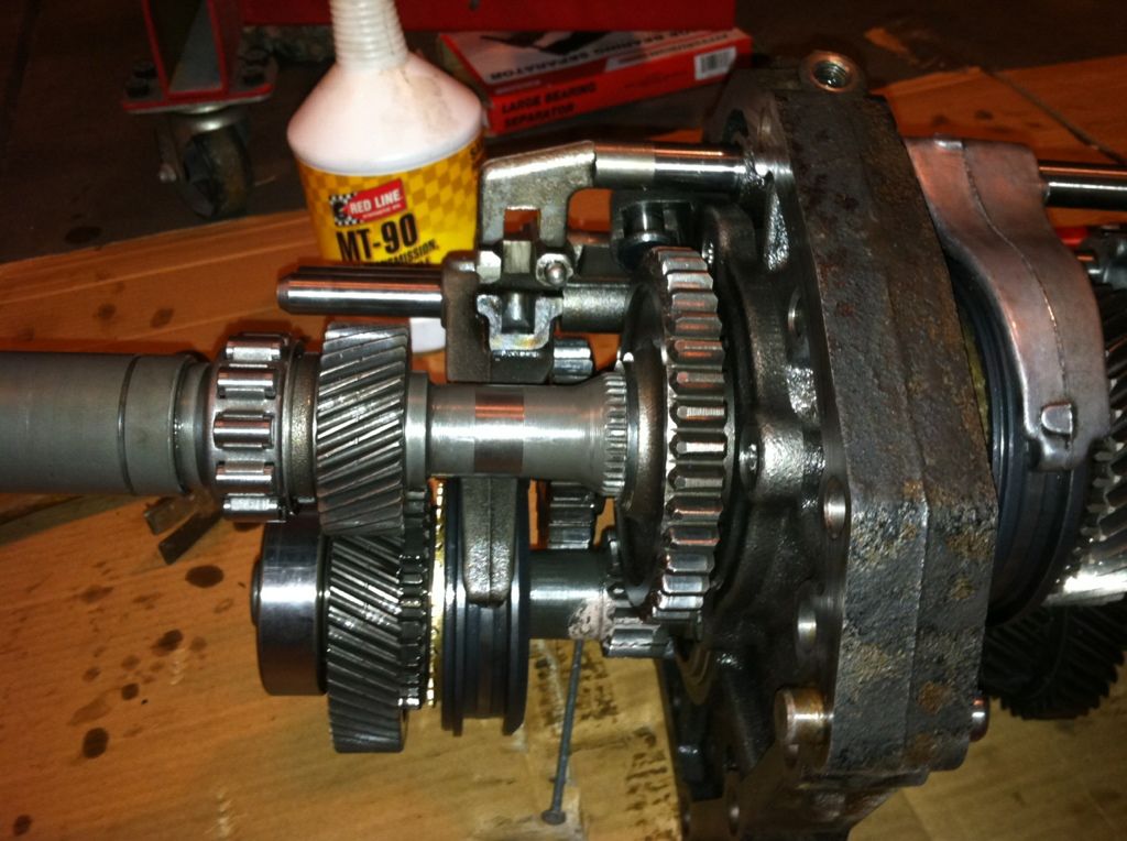
This is pic where the shortest of the 4 pins goes. There is a small notch in that shaft and you need to turn it so that it lines up with the pin, otherwise the other shaft will not slide in past it. The pin goes in the metal sleeve/brace/bracket that is on the shaft as shown. The shaft that goes through it has the small notch that needs to line up with the pin so that the other shaft that is just below it in the picture can slide through as well. Tough to explain, but it will make sense if you are doing it.
Last edited by live4soccer7; 08-29-2012 at 11:33 PM.
08-29-2012, 11:34 PM
#50
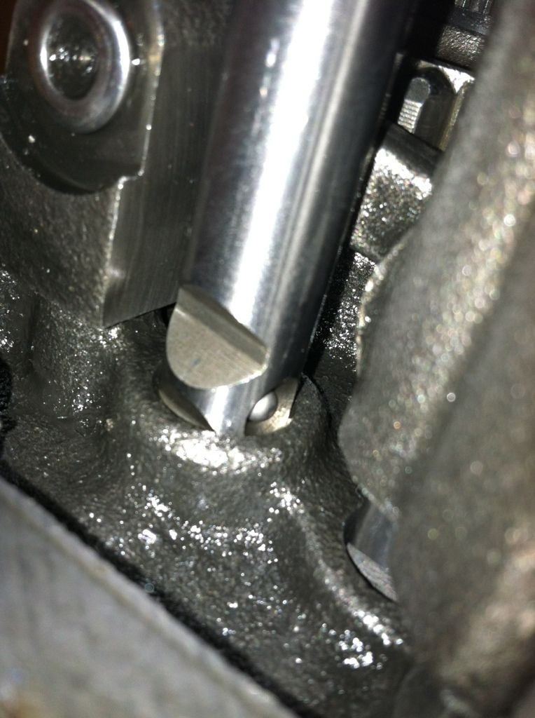
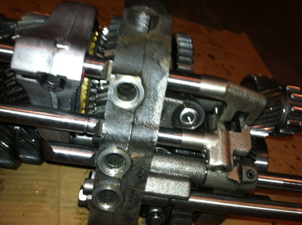
This is the thinnest in diameter of the 4 pins. It goes through the shaft right there as shown and then it slides through the middle plate where it will be held. To install this, I simply tipped the tranny sideways so the pin wouldn't fall out while getting it into place.
 08-29-2012, 11:41 PM
#54
There are a few things that I didn't take pictures of. Note that there are two bots with retaining brackets/clips that need to hold the shift forks on. There is also a roll pin in the other one that has be hammered in. The bolts torque to 9 ft-lbs and then you bend the locking tabs up. Be sure to note the direction of all of the shift forks and the directions and orientation of the shift rods/rails as well. There are also two "c" clips that I have not installed on two of the shift rails due to the fact that I lost one right of the get go. It shot across the garage at about a million miles an hour and was never to be seen again. I looked for an hour or two. I am finding a replacement now and then will post up the last few pics of the rebuild and hopefully have a success story on it as well when it goes for a test run.
Parts getting taken to the parts washer for a cleaning
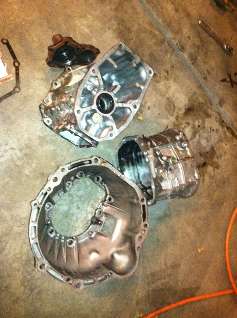
Parts getting taken to the parts washer for a cleaning
08-30-2012, 04:39 PM
#55
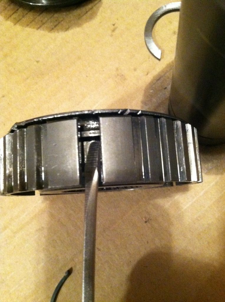
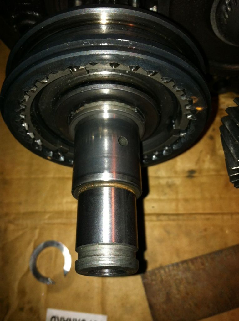
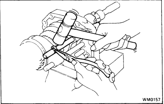
At the very beginning of the project, I think the first piece disassembled after removing the cases, I lost this snap ring as shown below. It shot across the garage at a very fast rate and who the **** knows where it went. I looked everywhere. It is likely sitting in a shoe or bucket or in some crazy weird place where it will be found in a few years. Anyways, in order to finish up the project and put the cases back on the tranny and get it up and running I'm in need of this snap ring. I am going to call the dealer tomorrow to see if they can get it, but I don't see any part #'s for it or anything.
If anyone has one of these from an old broken tranny or knows the part# it would be of great help.
If anyone has one of these from an old broken tranny or knows the part# it would be of great help.
Last edited by live4soccer7; 08-30-2012 at 04:42 PM.
 08-31-2012, 09:55 PM
#57
Diameter of shift fork shaft where the ring actually sits: .476"
Height of snap ring (just one side not diameter/radius): .10" (let me know if that doesn't make sense)
Thickness of snap ring: .06"
I didn't get a change to call up toyota or marlin. Hopefully on tuesday, after the holiday. If anyone has anything comparable please post up and let me know. The tranny is dead in the water until I get this. Thanks for any help.
09-03-2012, 01:10 PM
#58
Thanks for the detailed / step by step info. I just picked up a tranny open up and check out and see if its usable/rebuild-able. I got stuck taking it apart because the housing wouldn't separate, so I called it a day and checking here on you thread for ideas.
Thanks
Thanks
09-03-2012, 01:40 PM
#59
No problems, we got the input side off pretty easily I believe. Then the output side was a little more tricky. Make sure all the bolts that bolt into the middle plate are unbolted (not the allen ones) and then I think the only other thing you have to make sure about is the bot on top of the shift rail where the shifter went. At that point, it was a rubber mallet to get them to come apart.


