No Power to circuit opening relay
 09-01-2012, 06:29 PM
#1
Registered User
Thread Starter

Join Date: Sep 2012
Posts: 19
Likes: 0
Received 0 Likes
on
0 Posts
No Power to circuit opening relay
Hi all,
I'm new here, recently got a non-running 86 4runner.
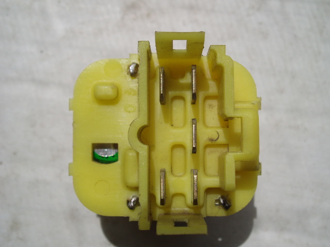
It's not getting fuel, i was hoping since it was sitting for a couple years it was going to be something simple like the relay or fuel pump, but when i pulled the relay to check, there was only power going to 1 of the 5 relay sockets. (the center one on the row of 3)
We also checked for power from all the fuses for the EFI system and etc in the fuse box in the driver side kick panel. They were all good and receiving power.
Do any of you guy have any idea what else to check or what could be going wrong? We figured it's bad wiring somewhere, but not sure where to begin sourcing parts of a harness and etc. (we're import car guys not so familiar with older toyota trucks)
Any help would be awesome!
I'm new here, recently got a non-running 86 4runner.
It's not getting fuel, i was hoping since it was sitting for a couple years it was going to be something simple like the relay or fuel pump, but when i pulled the relay to check, there was only power going to 1 of the 5 relay sockets. (the center one on the row of 3)
We also checked for power from all the fuses for the EFI system and etc in the fuse box in the driver side kick panel. They were all good and receiving power.
Do any of you guy have any idea what else to check or what could be going wrong? We figured it's bad wiring somewhere, but not sure where to begin sourcing parts of a harness and etc. (we're import car guys not so familiar with older toyota trucks)
Any help would be awesome!
 09-01-2012, 06:57 PM
#2
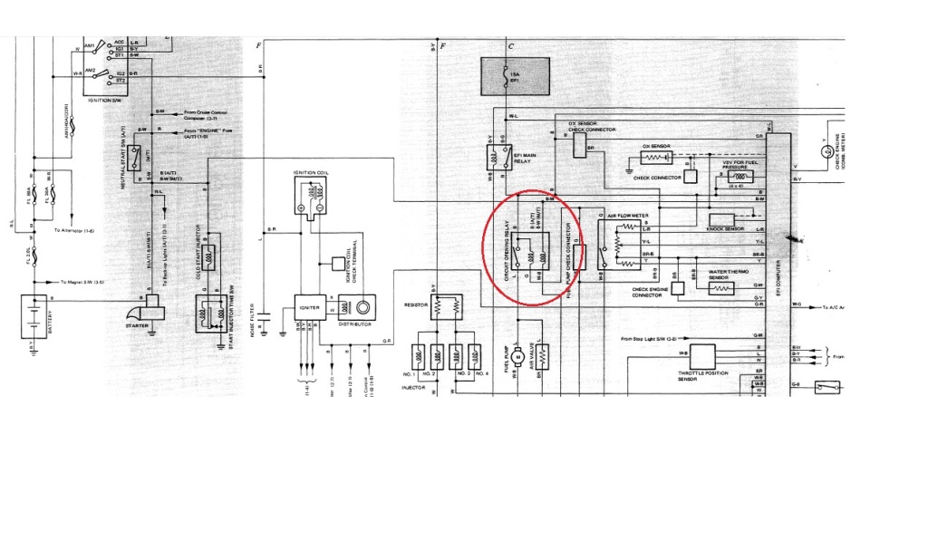
You check the fuel pump for operation? Jump terminals B+ & F in the check connector to test it; you should be able to hear the pump "hum" is it's working. The COR gets its power from the EFI main relay & powers the fuel pump. It is controlled by IGSW & AFM.
Check out this schematic:
Check out this schematic:
Last edited by streetlancer; 09-01-2012 at 07:02 PM.
09-01-2012, 07:30 PM
#3
To put that another way...
The EFI main relay sends power to the COR, which in turn sends power to the FP. But both the FC-E1 circuit(VAFM FC-E1 terminals), and the ST1-STA circuit(Ignition switch ST1 terminal to COR STA terminal) must be closed in order to close the +B-FP circuit(+B from EFI main relay to COR FP terminal) sending power to the fuel pump.
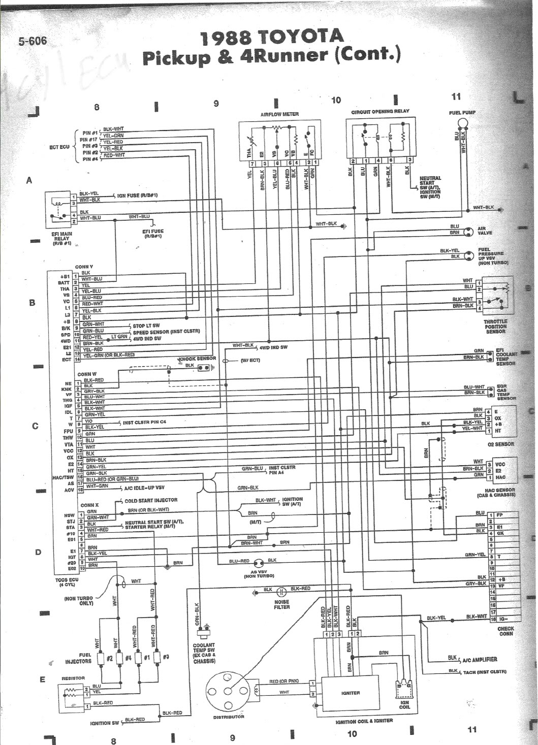
For the the rest of the circuits mentioned above see the 88 wiring diagram shown here:
https://www.yotatech.com/forums/f160.../#post51885494
The EFI main relay sends power to the COR, which in turn sends power to the FP. But both the FC-E1 circuit(VAFM FC-E1 terminals), and the ST1-STA circuit(Ignition switch ST1 terminal to COR STA terminal) must be closed in order to close the +B-FP circuit(+B from EFI main relay to COR FP terminal) sending power to the fuel pump.
For the the rest of the circuits mentioned above see the 88 wiring diagram shown here:
https://www.yotatech.com/forums/f160.../#post51885494
09-01-2012, 08:45 PM
#4
Registered User
Thread Starter
Join Date: Sep 2012
Posts: 19
Likes: 0
Received 0 Likes
on
0 Posts
I can't fully view the diagrams as I'm on my phone, but we tried to jump it as how most diagrams showed and still nothing. We checked to see if there was any power going to the opening circuit relay and only one of the sockets had power to it.
Not sure if that helps or if we're doing something wrong?
Not sure if that helps or if we're doing something wrong?
09-01-2012, 10:50 PM
#5
Registered User
Join Date: Mar 2008
Location: Temecula Valley, CA
Posts: 12,723
Likes: 0
Received 4 Likes
on
4 Posts
Mudhippy, do yourself a favor and look at the diagram you posted and make sure you understand it. The COR is a dual-coil relay: either attached circuit can be active and hold the COR on. It doesn't require both circuits to be active for the fuel pump to run, and if it did no 'yota with a VAFM would ever run.
The starting and air-flow meter circuits power parallel coils within the COR. One or the other has to be active for the COR to run.
The ignition switch (via the COR STA terminal) energizes the COR so the fuel pump runs while cranking and the AFM (FC) keeps the COR energized once the air flow to the engine is enough to keep it running.
It's all right there in the diagram you posted.
The EFI main relay sends power to the COR, which in turn sends power to the FP. But both the FC-E1 circuit(VAFM FC-E1 terminals), and the ST1-STA circuit(Ignition switch ST1 terminal to COR STA terminal) must be closed in order to close the +B-FP circuit(+B from EFI main relay to COR FP terminal) sending power to the fuel pump.
The ignition switch (via the COR STA terminal) energizes the COR so the fuel pump runs while cranking and the AFM (FC) keeps the COR energized once the air flow to the engine is enough to keep it running.
It's all right there in the diagram you posted.
Last edited by abecedarian; 09-01-2012 at 10:56 PM.
09-01-2012, 11:14 PM
#6
Registered User
Join Date: Mar 2008
Location: Temecula Valley, CA
Posts: 12,723
Likes: 0
Received 4 Likes
on
4 Posts
And I can hear it now:
"The AFM has to power that coil before you release the key or it will die so both have to be energized for the engine to run."
This is true to a point. The implication made, that both circuits were required to energize the COR and run the fuel pump is false.
If the engine starts and you release the key, there is already enough air flow through the VAFM to keep the COR energized.
It is an engine operating parameter issue- one requires the key to be turned and cranking the engine to start, and the other requires the engine to be running and sucking air.
And I can look at the diagrams and figure that out...
Last edited by abecedarian; 09-01-2012 at 11:18 PM.
09-02-2012, 07:27 AM
#7
Very well then. I stand corrected...kinda sorta. Let me just clarify what you've stated there.
Both circuits do need to be closed initially. But as soon as the engine begins to crank, not even started yet, the engine is sucking enough air through the VAFM to keep the FC-E1 circuit closed and, via power from the EFI main relay, allow the COR +B-FP circuit to close sending power to the FP. Then after the engine starts, the ST1-STA circuit is no longer required to be closed. Because the running engine can then sustain adequate air flow through the VAFM to keep the FC-E1 circuit closed. As such the ST1-STA circuit is only required to be closed to initiate the closing of the FC-E1 circuit.
Thanks for making that clear though. It could be a little misleading the way I worded it the first time. But I was really just trying to elaborate on the concept of how the "IGSW & AFM" control the COR. As I suggested by saying "To put that another way". So, in a sense, I wasn't wrong at all. It was you who read more into my statements than was meant to be told by them. Better you than someone else I guess. Atleast you know what you're talking about. Needless to say...you're right about that. And without including the words initially and/or initiate, I was wrong....in a sense.
To put that another way...
The EFI main relay sends power to the COR, which in turn sends power to the FP. But both the FC-E1 circuit(VAFM FC-E1 terminals), and the ST1-STA circuit(Ignition switch ST1 terminal to COR STA terminal) must be closed in order to close the +B-FP circuit(+B from EFI main relay to COR FP terminal) sending power to the fuel pump.
The EFI main relay sends power to the COR, which in turn sends power to the FP. But both the FC-E1 circuit(VAFM FC-E1 terminals), and the ST1-STA circuit(Ignition switch ST1 terminal to COR STA terminal) must be closed in order to close the +B-FP circuit(+B from EFI main relay to COR FP terminal) sending power to the fuel pump.
Last edited by MudHippy; 09-02-2012 at 08:04 AM.
Trending Topics
09-02-2012, 09:14 PM
#8
Registered User
Join Date: Mar 2008
Location: Temecula Valley, CA
Posts: 12,723
Likes: 0
Received 4 Likes
on
4 Posts
Okay, here goes:
Both circuits do need to be closed initially.
Strictly speaking, both circuits are OPEN initially. It's only when one turns the key to start the vehicle that things happen.
The VAFM part of the circuit is open initially and this is by design. Grab your multimeter and check for continuity to ground through the appropriate terminals on the VAFM. I'll bet you dollars-for-doughnuts it's not continuous to ground on a stock, un-modified vehicle with the key on or off, and the engine is not running. There's your "initial" VAFM circuit.
But as soon as the engine begins to crank, not even started yet, the engine is sucking enough air through the VAFM to keep the FC-E1 circuit closed
The VAFM? Um... nope: it only does that when there is enough air-flow to keep the COR grounded No air-flow = no COR = no fuel pump running... engine dies.
The best the VAFM sees when cranking is like pfft, pfft, pfft, pfft, pfft: the vane in the VAFM is oscillating from closed to open to closed to open.... and it would be doing the same to the COR and fuel pump: on, off, on, off, on, off....
Were it not for the ignition switch holding the COR (and fuel pump) on, a 'yota would be pretty hard to start. Imagine how it would be cranking your engine waiting for the VAFM to close the COR so the fuel pump comes on. And the longer it takes, the lower the battery voltage and the slower the engine cranks... REDUCING the air flow....
Try it some time- disconnect the (STA) lead from the COR. Let me know how it goes.
...>snip<...
Then after the engine starts, the ST1-STA circuit is no longer required to be closed. Because the running engine can then sustain adequate air flow through the VAFM to keep the FC-E1 circuit closed. As such the ST1-STA circuit is only required to be closed to initiate the closing of the FC-E1 circuit.
Thanks for making that clear though. It could be a little misleading the way I worded it the first time. But I was really just trying to elaborate on the concept of how the "IGSW & AFM" control the COR. As I suggested by saying "To put that another way". So, in a sense, I wasn't wrong at all. It was you who read more into my statements than was meant to be told by them. Better you than someone else I guess. Atleast you know what you're talking about. Needless to say...you're right about that. And without including the words initially and/or initiate, I was wrong....in a sense.
And for the record, I may have made mistakes within what I wrote.
If you happen to find any, please feel free to call me out on them.
09-03-2012, 06:55 AM
#9

Oh really? Sure dude whatever you say...

You've once again FULLY misunderstood what I said.
What else are you still misunderstanding?
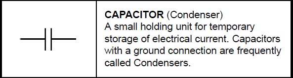
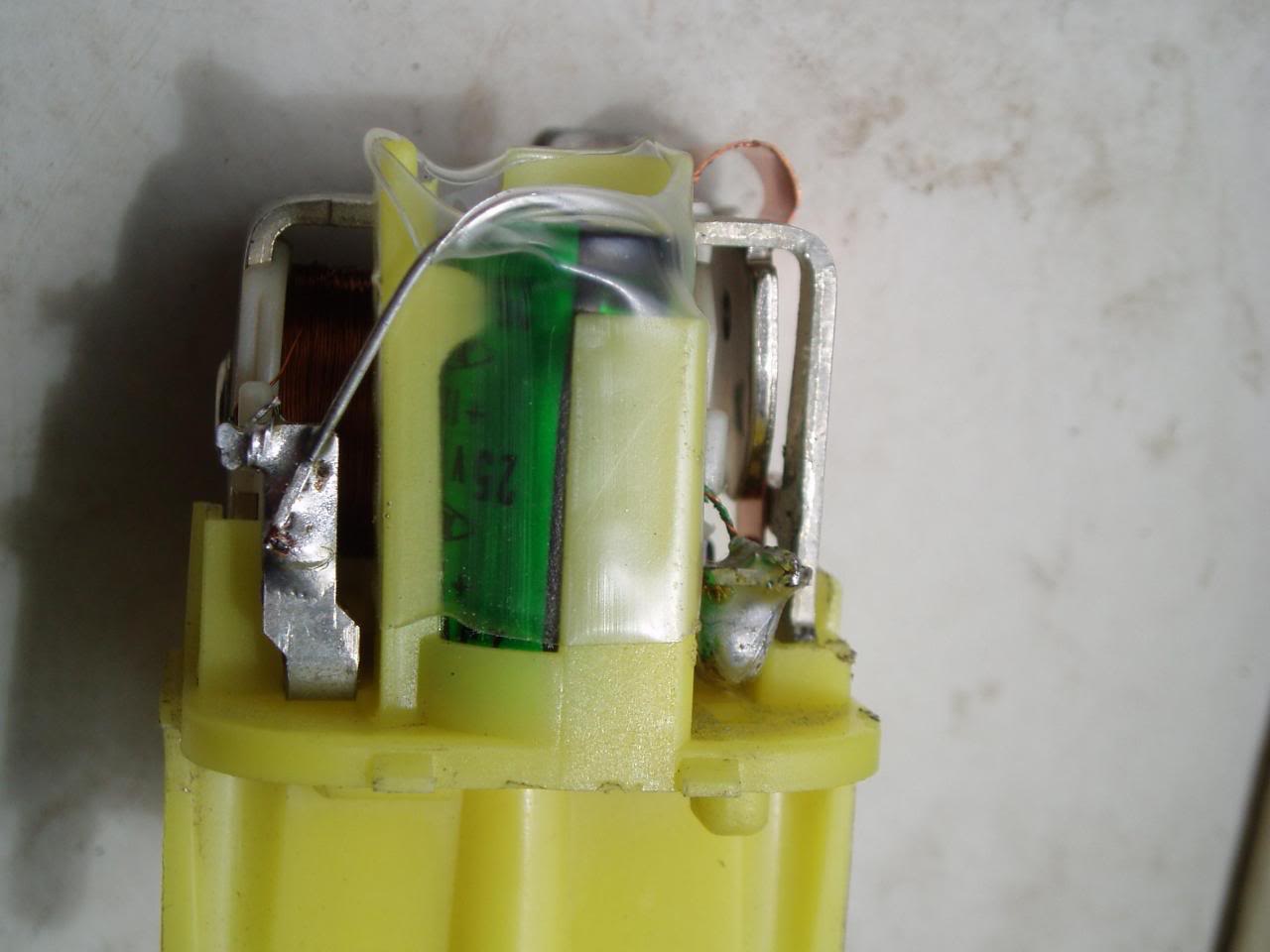
Hint 1: There's a capacitor in the COR for a reason. But it's not necessarily there for when the engine is cranking. Though in theory it might be useful then, if there were a fault in the STA circuit.
Last edited by MudHippy; 09-03-2012 at 07:30 AM.
09-03-2012, 09:34 AM
#10
Registered User
Join Date: Mar 2008
Location: Temecula Valley, CA
Posts: 12,723
Likes: 0
Received 4 Likes
on
4 Posts
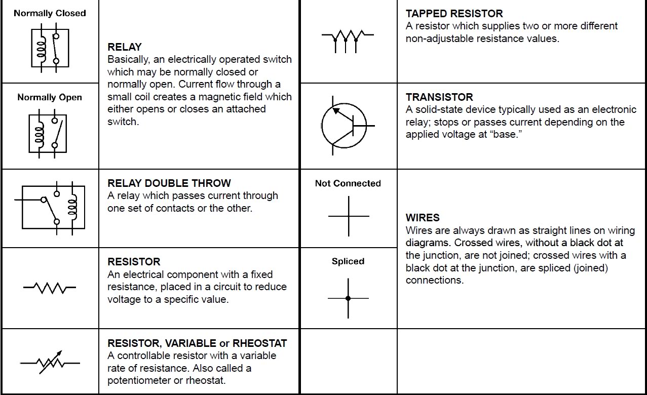
Anyhow, a series resistor / capacitor combination across a relay coil is used to clamp the voltage spike (flyback) which can occur when current to a coil is interrupted and the field collapses. This reduces "noise" and helps prevent over-voltage damage to connected components, which would include everything connected to B+.
If the intent was to hold the relay closed momentarily while cranking because of VAFM oscillations, the capacitor would be wired across the coil without the resistor and would be polarized, not non-polarized as is indicated by the diagram below.

Last edited by abecedarian; 09-03-2012 at 09:36 AM.
09-03-2012, 09:40 AM
#11
The earlier trucks have a slightly different COR setup:
- http://www.4crawler.com/4x4/CheapTri...shtml#FuelPump
COR testing:
- http://www.4crawler.com/4x4/CheapTri...ORelayLocation
- http://www.4crawler.com/4x4/CheapTri...shtml#FuelPump
COR testing:
- http://www.4crawler.com/4x4/CheapTri...ORelayLocation
09-03-2012, 10:14 AM
#12
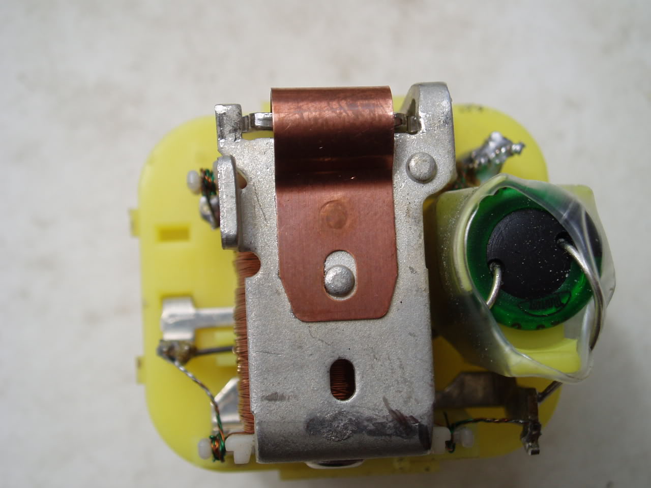
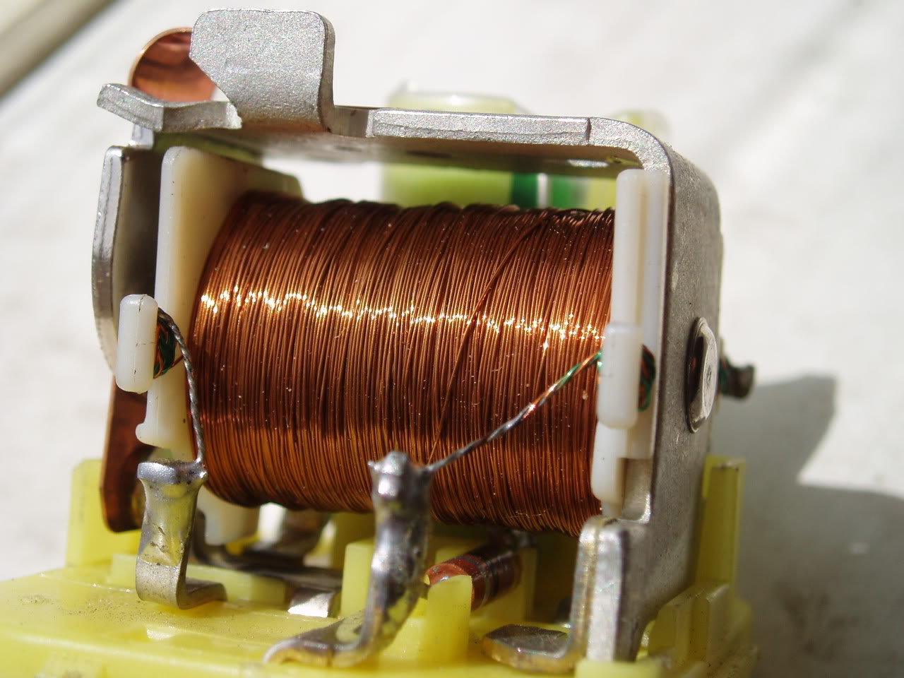
Cheap fixes for your circuit opening relay - overview, new capacitor install, refurbing contacts, swapping in a higher uF capacitor to prevent AFM signal loss, etc. Hate reading threads about people spending $$$ for new ones...
http://www.youtube.com/watch?v=V8l9QvLAajA
http://www.youtube.com/watch?v=V8l9QvLAajA
The main point of having the capacitor is to keep the Fp circuit closed if the VAFM measuring plate were to momentarily close/open the Fc circuit while the engine were running. Such as might happen when the engine is idling while the vehicle is travelling over a rough/steeply declined surface. Where the low rpm wouldn't be holding the VAFM measuring plate very far open to begin with(or when the measuring plate slams shut due to the intake air volume suddenly dropping). But it works just as well to keep the Fp circuit closed in such a manner while the engine is cranking/not yet running. Since, even while the engine is just cranking/not yet running, the VAFM is required to keep the Fc circuit held closed while the measuring plate is in any position OTHER THAN FULLY CLOSED!!! FSM specifications dictate precisely that. Not to mention the fact that some models have no STA circuit in the COR. With that type of COR the fuel pump CAN'T be switched on INITIALLY by the action of the starter/STA circuit, but instead the closing of the Fp circuit MUST be INITIATED by the action of the starter turning the engine over, thereby drawing air through the AFM and closing the Fc circuit(hence they NEED the capacitor in the Fp circuit during starting on these models).
Watch the vid, explains it all.
Pages 8 & 9 from this pdf also explain it as described above.
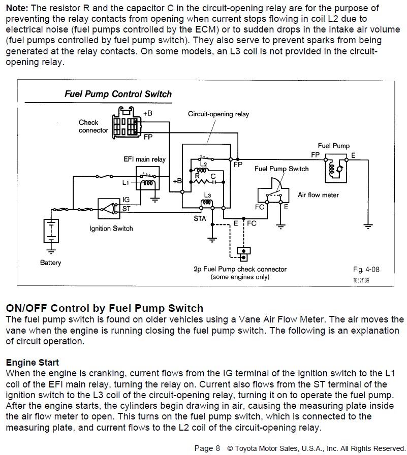
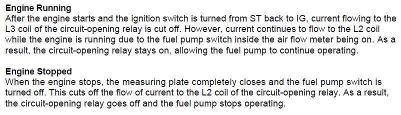
http://www.autoshop101.com/forms/h42.pdf
Last edited by MudHippy; 09-03-2012 at 03:03 PM.

Thread
Thread Starter
Forum
Replies
Last Post


