Cold Start Injector Low Voltage (22re)
 01-01-2016, 08:33 PM
#1
Registered User
Thread Starter

Join Date: Dec 2010
Posts: 121
Likes: 0
Received 0 Likes
on
0 Posts
Cold Start Injector Low Voltage (22re)
1987 22RE m/t
I've been experiencing long cranking for a while now. Never had a problem with the engine not starting, just taking longer than normal to fire on a cold start. Sometimes it'll pop once and then need another crank to get it going. Anyways, I suspected something is wrong with the cold start injector system.
Ohm checked the injector and it was fine (around 3 ohms) but I pulled the injector and cleaned it up anyways. Then I hooked it up leaving it outside the intake to see if I was getting a spray or not (cold engine). During cranking I didn't get any spray.
I hot-wired 12v to the injector and got a nice, steady spray. So the injector is fine. Next, on to the time switch. Ohm checked the time switch (cold engine) and got around 30 ohms between the time switch terminals. This is normal from what I've read.
With the injector and time switch unplugged I did a continuity check and the wiring looked fine. Lastly, I checked the voltage at the injector plug while the key is in START (injector/time switch still unplugged) and this is where it get interesting. I only got 7 volts. (during this test I had the + battery cable going to the starter disconnected so I could test without the engine turning over...the starter solenoid still operated as normal)
Looking at the circuit diagram, the wiring goes from the battery through the ignition switch and starter relay before going to the cold start injector circuit and starter solenoid. So...I'm not really sure how I could be getting 7 volts at the injector. Unless the voltage is dropping across the ignition switch or relay? But would the starter solenoid even operate on 7 volts? I didn't check the battery during the test, but I wouldn't expect it to drop to 7 volts. I'll have to check that tomorrow. I could also check the voltage at the solenoid.
The starter was replaced less than a year ago (reman unit) and I haven't had any issues with the starter not cranking...something I would anticipate if the solenoid wasn't getting a full 12v.
Any thoughts?
 01-01-2016, 09:17 PM
#2
Registered User
Thread Starter
Join Date: Dec 2010
Posts: 121
Likes: 0
Received 0 Likes
on
0 Posts
I've been digging around and couldn't find anyone with the exact problem I am having, but I did some searching on low voltage at the start solenoid (the same voltage that the CSI should see).
One possible problem is worn out contacts in the ignition switch which causes a voltage drop. This makes sense because a lot of current passes through the ignition switch when energizing the starter solenoid. EXCEPT, people that have this problem experience no-cranking because the solenoid doesn't get enough voltage to operate. So far I haven't experienced a no-crank incident...but maybe the starter solenoid is still able to operate fine at the lower voltage? Looks like I'll have to do some more testing to see what the voltage is at the solenoid/CSI during starting.
Here is a mod I found about rewiring the solenoid wiring to utilize the starter relay like it suppose to be (eliminating the high current through the *ignition switch):
http://www.toyota-4runner.org/classi...ml#post1284393
We'll see if all signs point to a worn out ignition switch, then I can make that easy mod and hopefully fix my low voltage problem.
Last edited by jstluise; 01-02-2016 at 12:02 PM. Reason: *Said starter relay when I meant ignition switch
01-01-2016, 10:34 PM
#3
Here is a mod I found
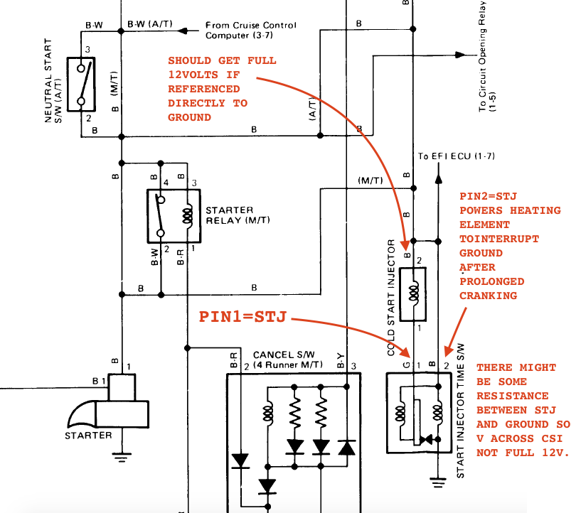
 and fix what had been proven to be broken. I'm sure it will take less than an hour to do, will help extend the life of your ignition switch, and ensure you get a full 12 volts at CSI positive pin. Quick and clean fix is here.
 Once you correct that issue (a 30-minute fix), you should get full12V at the positive side of the CSI IF negative probe is directly to ground (Schematic below), regardless of the condition of the ignition switch.
...people that have this problem experience no-cranking because the solenoid doesn't get enough voltage to operate. So far I haven't experienced a no-crank incident...but maybe the starter solenoid is still able to operate fine at the lower voltage?
Looks like I'll have to do some more testing to see what the voltage is at the solenoid/CSI during starting.
However, because there may be some normal resistance between STJ pin of the CSI timer switch, you may observe less than 12Volts IF you measure between the 2 pins of the CSI connector.
Please keep us posted, because I'm also digging into that same circuit, here.
Last edited by RAD4Runner; 01-01-2016 at 10:41 PM.
01-02-2016, 11:38 AM
#4
Registered User
Thread Starter
Join Date: Dec 2010
Posts: 121
Likes: 0
Received 0 Likes
on
0 Posts
Excellent! Thanks for the response. Hopefully I'll have time later today to investigate this further, but I'll be sure to report back. A worn out ignition switch definitely sounds like the culprit. But regardless, I'll do the mod just because it is the right way it should be wired. I can't believe I didn't run across this mod in all the years I've been wrenching on the truck and visiting the forums, especially when I was having starting issues due to a loose solenoid wire connection. Oh well, better late than never!
I did run across this thread: http://forum.ih8mud.com/threads/22re...lenoid.302032/
The OP reports varying solenoid voltage (7-8v when it doesn't start and 11v when it does). Ultimately they report a bad solenoid contact/plunger was the problem. I don't think the bad plunger was causing the varying voltage at the solenoid (it doesn't make sense how it could), but rather the ignition switch was acting up, sometimes making good contact and sending 11v and other times not making good contact which means a lower voltage. The OP replaced the solenoid contacts and now it works fine at the high or low voltage (just like mine is working fine at the low voltage). That's my best guess anyways...I can't see how the solenoid contacts could be causing that issue.
01-02-2016, 01:22 PM
#5
I did run across this thread... I don't think the bad plunger was causing the varying voltage at the solenoid (it doesn't make sense how it could), but rather the ignition switch was acting up, sometimes making good contact and sending 11v and other times not making good contact which means a lower voltage. The OP replaced the solenoid contacts and now it works fine at the high or low voltage (just like mine is working fine at the low voltage). That's my best guess anyways...I can't see how the solenoid contacts could be causing that issue.
Last edited by RAD4Runner; 01-02-2016 at 01:29 PM.
01-03-2016, 08:12 PM
#6
Registered User
Thread Starter
Join Date: Dec 2010
Posts: 121
Likes: 0
Received 0 Likes
on
0 Posts
I confirmed today that I am indeed only getting 7 volts to the starter solenoid (and therefore the CSI) during starting. With everything hooked up I probed the solenoid wire directly to check this. I didn't have any heavier gauge wire on hand today so I'll have to pick some up this week to do the wiring mod. That should get me the 12v I need.
I am wondering about how the CSI time switch works, specifically the heating element that interrupts the ground. I unplugged the CSI checked the voltage one each pin during starting (within a minute of the previous test). I got 7 volts on BOTH pins, which seemed odd since I thought pin 1 is hooked to ground. Either my time switch isn't working correctly or my previous testing caused the heating element to interrupt the ground...
When the heating element interrupts the ground, does it just let it float or does it connect pin 1 and pin 2? Do you know how quickly the interrupt occurs during cranking? I'm hoping the interrupt just shorts pin 1 and pin 2 (disabling the CSI) and I just didn't give the heater enough time to cool down and reset.
Thanks for the help!
01-04-2016, 01:21 AM
#7
I am wondering about how the CSI time switch works, specifically the heating element that interrupts the ground. I unplugged the CSI checked the voltage one each pin during starting (within a minute of the previous test). I got 7 volts on BOTH pins, which seemed odd since I thought pin 1 is hooked to ground. Either my time switch isn't working correctly or my previous testing caused the heating element to interrupt the ground...
...When the heating element interrupts the ground, does it just let it float or does it connect pin 1 and pin 2? Do you know how quickly the interrupt occurs during cranking? I'm hoping the interrupt just shorts pin 1 and pin 2 (disabling the CSI) and I just didn't give the heater enough time to cool down and reset.
I haven't verified yet whether:
(1) CSI timer has full control of grounding the STJ, OR
(2) ECU also take over grounding the STJ Pin of CSI.
Relevant article here.
Trending Topics
01-04-2016, 07:55 AM
#8
Registered User

Join Date: Sep 2007
Location: San Francisco East Bay
Posts: 8,252
Likes: 0
Received 820 Likes
on
648 Posts
here's the wiring diagram of a CSI Time Switch:
http://web.archive.org/web/201411140...ne/97colds.pdf
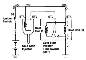
Rad4Runner's diagram is (mostly) correct. According to the diagram in the manual, STA (at the CSI) is connected straight to the ignition switch. STJ (at the CSI) connects to STJ on the Time switch. When cold, STJ is grounded, so with key to start the CSI opens.
But when the CSI Time Switch opens (long cranking) the manual shows it connected through a coil (heater? magnetic?) back to STA. Since you're not drawing any current with your multimeter it just gives you STA voltage again.
I have NOT checked this "in the field."
http://web.archive.org/web/201411140...ne/97colds.pdf
Rad4Runner's diagram is (mostly) correct. According to the diagram in the manual, STA (at the CSI) is connected straight to the ignition switch. STJ (at the CSI) connects to STJ on the Time switch. When cold, STJ is grounded, so with key to start the CSI opens.
But when the CSI Time Switch opens (long cranking) the manual shows it connected through a coil (heater? magnetic?) back to STA. Since you're not drawing any current with your multimeter it just gives you STA voltage again.
I have NOT checked this "in the field."
01-04-2016, 08:19 AM
#9
Registered User
Thread Starter
Join Date: Dec 2010
Posts: 121
Likes: 0
Received 0 Likes
on
0 Posts
Scope beat me to it. The awesome reference that RAD linked to shows much more detail on the time switch circuit (starts on page 20) and answers all my questions about how it works.
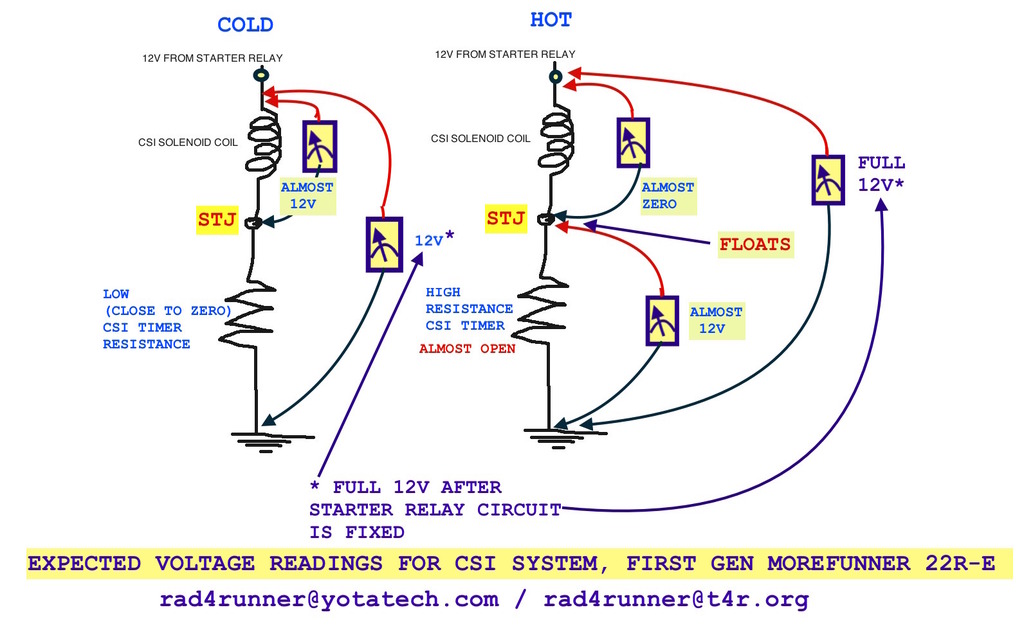
There are two heating coils in the time switch and a bi-metallic contact. When cold, the bi-metallic contact is shorted to ground and you have current flowing through both heaters, and the current flowing through STJ goes straight to ground.
Cold Starting (CSI time switch ON):

When the bi-metallic contact heats up (either from the heaters during extended starting or from hot coolant), the short to ground is broken and now STJ is not floating, but rather connected to STA through one of the heaters. This essentially puts STA and STJ at the same voltage, which means the CSI will have zero potential across it and won't fire.
Warm Starting (CSI time switch OFF):
And here is a chart that shows the injector duration, which explains how long it takes for the bi-metallic contact to heat up during starting:
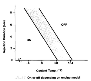
For example, if the temp is around 50F, the injector will be on between 1-5 seconds before the time switch goes OFF.
What I believe happened in my last round of testing was during my check on the solenoid voltage I caused the time switch to go OFF because I had power to the solenoid (STA) for too long. Then, without allowing the time switch to cool down I immediately checked the voltage at STA and STJ (with respect to ground) with the CSI unplugged. This is why I got the almost identical voltage on STA and STJ (they were very slightly different due to the loss across one of the heaters). I'll have to test it again, but making sure everything is cold. But, what happens make sense.
Oh, and to answer RAD's questions, I did all my probing with respect to ground.
There are two heating coils in the time switch and a bi-metallic contact. When cold, the bi-metallic contact is shorted to ground and you have current flowing through both heaters, and the current flowing through STJ goes straight to ground.
Cold Starting (CSI time switch ON):
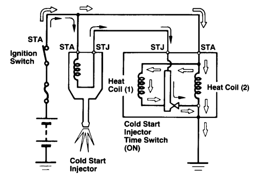
When the bi-metallic contact heats up (either from the heaters during extended starting or from hot coolant), the short to ground is broken and now STJ is not floating, but rather connected to STA through one of the heaters. This essentially puts STA and STJ at the same voltage, which means the CSI will have zero potential across it and won't fire.
Warm Starting (CSI time switch OFF):

And here is a chart that shows the injector duration, which explains how long it takes for the bi-metallic contact to heat up during starting:

For example, if the temp is around 50F, the injector will be on between 1-5 seconds before the time switch goes OFF.
What I believe happened in my last round of testing was during my check on the solenoid voltage I caused the time switch to go OFF because I had power to the solenoid (STA) for too long. Then, without allowing the time switch to cool down I immediately checked the voltage at STA and STJ (with respect to ground) with the CSI unplugged. This is why I got the almost identical voltage on STA and STJ (they were very slightly different due to the loss across one of the heaters). I'll have to test it again, but making sure everything is cold. But, what happens make sense.
Oh, and to answer RAD's questions, I did all my probing with respect to ground.
Last edited by jstluise; 01-04-2016 at 08:21 AM.
01-04-2016, 11:38 AM
#10
Thanks for the thorough analysis, guys!
Turns out that:
Turns out that:
(1) On some trucks (like the 1986) the CSI Timer Switch has full control of ground for CSI, like jstluise describes above
(2) On others, like in Scope103's diagram, the ECU takes part in controlling ground.
1988's schematic shows (1), but the CSI Timer check section on page FI-75 shows (2). Conflicting. Terry87 has a post somewhere about change in the CSI timer switch. Perhaps the change happened on the 1988 but Toyota failed to update the schematic.
On 1987... jstluise may just have to do the field check
I detailed discussion on my thread here for easy reference.
(2) On others, like in Scope103's diagram, the ECU takes part in controlling ground.
1988's schematic shows (1), but the CSI Timer check section on page FI-75 shows (2). Conflicting. Terry87 has a post somewhere about change in the CSI timer switch. Perhaps the change happened on the 1988 but Toyota failed to update the schematic.
On 1987... jstluise may just have to do the field check
01-04-2016, 12:24 PM
#11
Registered User
Thread Starter
Join Date: Dec 2010
Posts: 121
Likes: 0
Received 0 Likes
on
0 Posts
Hmm, interesting. Nice detective work! I'll have see if I can figure out what the configuration is on my '87.
I'll unplug the CSI and CSI time switch, then ohm check STJ-GND during starting to see if the ECU does anything to it. If I do have the STJ wire to the ECU, then I should see a short for a few seconds until the ECU breaks the connection.
I'll report back!
I'll unplug the CSI and CSI time switch, then ohm check STJ-GND during starting to see if the ECU does anything to it. If I do have the STJ wire to the ECU, then I should see a short for a few seconds until the ECU breaks the connection.
I'll report back!
01-04-2016, 01:25 PM
#12
Registered User
Join Date: Sep 2007
Location: San Francisco East Bay
Posts: 8,252
Likes: 0
Received 820 Likes
on
648 Posts
RAD4Runner does a better job than I can in tracking the "history" of wiring changes. But here's a Toyota publication with more description:
http://www.cygnusx1.net/Media/Supra/...taTech/h22.pdf
(did jtluise get his drawings from there?) That article implies that the ECU control of the STJ line may be in the form of a fail-safe. But that doesn't make a lot of sense to me; how would the ECU know the CSI timer failed?
http://www.cygnusx1.net/Media/Supra/...taTech/h22.pdf
(did jtluise get his drawings from there?) That article implies that the ECU control of the STJ line may be in the form of a fail-safe. But that doesn't make a lot of sense to me; how would the ECU know the CSI timer failed?
01-04-2016, 01:37 PM
#13
Registered User
Thread Starter
Join Date: Dec 2010
Posts: 121
Likes: 0
Received 0 Likes
on
0 Posts
RAD4Runner does a better job than I can in tracking the "history" of wiring changes. But here's a Toyota publication with more description:
http://www.cygnusx1.net/Media/Supra/...taTech/h22.pdf
(did jtluise get his drawings from there?) That article implies that the ECU control of the STJ line may be in the form of a fail-safe. But that doesn't make a lot of sense to me; how would the ECU know the CSI timer failed?
http://www.cygnusx1.net/Media/Supra/...taTech/h22.pdf
(did jtluise get his drawings from there?) That article implies that the ECU control of the STJ line may be in the form of a fail-safe. But that doesn't make a lot of sense to me; how would the ECU know the CSI timer failed?
It's a fail-safe because the ECU will always ground STJ (if needed, according to the coolant temp sensor) regardless of what the timer switch is doing. As noted in the article, the ECU will turn on the CSI as long as the coolant temp is below 113F. If the temp is below 77F, then both the time switch and ECU can turn the CSI (since they are just providing ground they can both ground at the same time without conflict).
In the event that the time switch fails (gets stuck open, doesn't provide ground), then the ECU will be there as a back up. The ECU does not know that the time switch failed...it's just doing what it always does.
01-04-2016, 05:40 PM
#14
COOL! Three cool heads are better than one
01-04-2016, 09:19 PM
#15
Registered User
Thread Starter
Join Date: Dec 2010
Posts: 121
Likes: 0
Received 0 Likes
on
0 Posts
Tonight after work I wired up the mod, bypassing the ignition switch and wiring up pin 4 of the starter relay directly to pin 3 of fuse AM1. Then, with the CSI and time switch unplugged (starter solenoid connected), I probed the solenoid/STA w.r.t ground: 9.5V.
Hmmm. A little better, but not the 12V I was hoping for. Now that I have the mod in place, the only components between batt+ and STA are fuse AM1, the starter relay, and associated wiring. So, I probed everything I could while the key was in START (CSI and time switch still unplugged):
GND-BATT+ = 11.4V (yeah, my battery is tired and needs to be replaced)
GND-Start Relay Pin 4 = 11.4V (good, no drop across AM1 or my new wiring)
GND-Start Relay Pin 2 = 10.2V (bad, 1.2V drop across relay contacts)
GND-STA = 9.5 (not great, another 0.7V drop across the wiring)
Now the question is what the minimum operating voltage of the CSI is. Obviously I can gain a volt with a healthy battery, but I can also gain another volt by replacing the starter relay with a new one (typical 30A relays have drops less than 0.25V). If necessary I can run a wire directly from the starter relay to the CSI which would pick up another 0.5V or so.
My coolant was still to warm from the drive home to do any actual testing with the CSI or time switch, so I'll have to do that another time. I'll do a cold start in the morning with the CSI hooked up to see if I notice any difference. Maybe the couple volts I gained so far is enough to operate the CSI. We'll see!
Last edited by jstluise; 01-04-2016 at 09:27 PM. Reason: Submission error - not all content was submitted.
01-05-2016, 05:32 AM
#16
Registered User
Join Date: Sep 2007
Location: San Francisco East Bay
Posts: 8,252
Likes: 0
Received 820 Likes
on
648 Posts
I fear something else is going on here. Your meter draws basically "no" current, and you need current for any voltage drop (Ohm's law). Even if your starter relay had a 2 ohm contact resistance (pretty high), that requires 600ma flowing through it to get a 1.2v drop.
You could have a damaged wire somewhere that is "leaking" 600ma (or so) to ground through a dirty, greasy, slightly conductive path. You might even try putting your ammeter on the circuit to check directly. (But don't over-do this; your meter isn't "infinitely" accurate, and you are using current somewhere just to pull in the relay contacts, so without carefully working through the wiring diagram I can't be accurate "to the last milliamp.")
You could have a damaged wire somewhere that is "leaking" 600ma (or so) to ground through a dirty, greasy, slightly conductive path. You might even try putting your ammeter on the circuit to check directly. (But don't over-do this; your meter isn't "infinitely" accurate, and you are using current somewhere just to pull in the relay contacts, so without carefully working through the wiring diagram I can't be accurate "to the last milliamp.")
Last edited by scope103; 01-05-2016 at 05:36 AM.
01-05-2016, 06:31 AM
#17
Thanks for the thorough analysis, guys!
Turns out that:
Turns out that:
(1) On some trucks (like the 1986) the CSI Timer Switch has full control of ground for CSI, like jstluise describes above
(2) On others, like in Scope103's diagram, the ECU takes part in controlling ground.
1988's schematic shows (1), but the CSI Timer check section on page FI-75 shows (2). Conflicting. Terry87 has a post somewhere about change in the CSI timer switch. Perhaps the change happened on the 1988 but Toyota failed to update the schematic.
On 1987... jstluise may just have to do the field check
I detailed discussion on my thread here for easy reference.(2) On others, like in Scope103's diagram, the ECU takes part in controlling ground.
1988's schematic shows (1), but the CSI Timer check section on page FI-75 shows (2). Conflicting. Terry87 has a post somewhere about change in the CSI timer switch. Perhaps the change happened on the 1988 but Toyota failed to update the schematic.
On 1987... jstluise may just have to do the field check
wally
Last edited by wallytoo; 01-05-2016 at 06:33 AM.
01-05-2016, 07:35 AM
#18
Registered User
Thread Starter
Join Date: Dec 2010
Posts: 121
Likes: 0
Received 0 Likes
on
0 Posts
So I did a cold start this morning and I was happy to experience a quick start! It's been a while since I've experienced that! Two to three cranks and it fired right up like the old days! No prolonged cranking with spitting and sputtering before getting going. So, I'd say those extra couple volts I gained was enough to actuate the CSI.
I'll leave the starter relay alone for now, even though I'm sure the contacts have seen better days. When I get a new battery I'll be in even better shape.
I'm still going to tinker with the time switch to see if the ECU plays any part in the CSI circuit. But it sounds like wally verified the '87 FSM doesn't show a connection to the ECU.
Thanks all for your help!

Thread
Thread Starter
Forum
Replies
Last Post
mick.j.becker
General Electrical & Lighting Related Topics
13
11-01-2015 09:49 AM
ET
95.5-2004 Tacomas & 96-2002 4Runners
5
10-22-2015 01:37 AM


