
been thinkin of a better cold air intake setup...
 08-19-2013, 12:10 PM
#41
Registered User
Ok Guys,
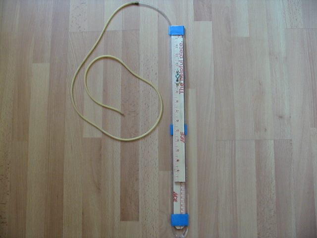
Following the information provided by the Autospeed.com articles, I've constructed what's called a "slack-tube manometer" to measure the pressure drop in my intake system. This instrument reliably and accurately measures the pressure drop in units of "inches of water." Additionally, it will give me a measure of how restrictive my intake is in comparison to atmospheric pressure. I also built in a "zero calibration" feature that allows me to align the "0" of the ruler with the left-side meniscus.
Materials needed:
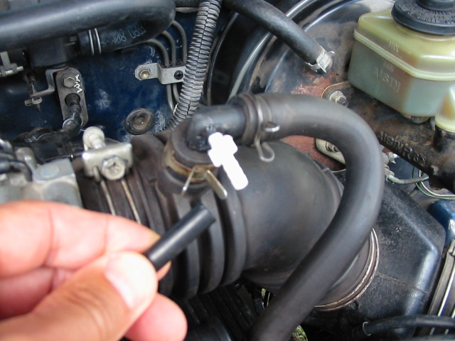
The first data collection point. This location will provide the total pressure-drop in the OEM intake system (includes the drop-in K&N filter that I bought 24 years ago.) Materials: 3/16" hose barb, 3/16" cap, and a bit of silicon sealer.
I'll add at-speed, real-time driving data as I collect them. (Sorry about the table format. I'm not able to use HTML code at the moment.)
Initial measurement and instrument setup results:
Speed (mph).....Pressure Drop (inWC).....Ambient Air Temp. (�F)
idle...................................1-1/4................................73
65-70................................1-1/4~1-3/8�...................71
WOT..................................6~7�......... ......................71
�Level highway, 5th gear
�Highway on-ramp, 2nd gear, 0.21654 to 0.25263 PSI maximum restriction
Instrument setup notes:
Conversion Units:
1 inWC = 0.03609 PSI or 0.00246 atm
I'll post a couple pics from the setup phase once the camera's batteries are re-charged. Stay tuned...because I'm going to be collecting data after this point, taking more pics, and analyzing that data for trends.
Following the information provided by the Autospeed.com articles, I've constructed what's called a "slack-tube manometer" to measure the pressure drop in my intake system. This instrument reliably and accurately measures the pressure drop in units of "inches of water." Additionally, it will give me a measure of how restrictive my intake is in comparison to atmospheric pressure. I also built in a "zero calibration" feature that allows me to align the "0" of the ruler with the left-side meniscus.
Materials needed:
- Common wooden yardstick
- ~4' of 1/8" aquarium clear tubing
- Masking tape or clear tape
- Vacuum (or surgical tubing in my case)
- Hose/tubing union (mine was a brass fueling connector from my R/C stuff)
- bolt, washer, and wingnut
The first data collection point. This location will provide the total pressure-drop in the OEM intake system (includes the drop-in K&N filter that I bought 24 years ago.) Materials: 3/16" hose barb, 3/16" cap, and a bit of silicon sealer.
I'll add at-speed, real-time driving data as I collect them. (Sorry about the table format. I'm not able to use HTML code at the moment.)
Initial measurement and instrument setup results:
Speed (mph).....Pressure Drop (inWC).....Ambient Air Temp. (�F)
idle...................................1-1/4................................73
65-70................................1-1/4~1-3/8�...................71
WOT..................................6~7�......... ......................71
�Level highway, 5th gear
�Highway on-ramp, 2nd gear, 0.21654 to 0.25263 PSI maximum restriction
Instrument setup notes:
- With my shocks being worn-out, road surface irregularities would make the truck's front end to "bounce" up and down
 , causing the meniscus to also rapidly move up and down. This could make it difficult to take a reading
  .
. - Using two temperature measuring devices suggests that I should complete an I-MR chart study to understand the variability in my instruments. I'll use Minitab 16 statistical software for this. Taylor inside/outside thermometers, model #1522 were used.
- K&N air filter last cleaned/re-oiled on 6/15/2013. 491 miles incurred since then.
Conversion Units:
1 inWC = 0.03609 PSI or 0.00246 atm
I'll post a couple pics from the setup phase once the camera's batteries are re-charged. Stay tuned...because I'm going to be collecting data after this point, taking more pics, and analyzing that data for trends.
Last edited by skipper0802; 08-21-2013 at 09:40 AM. Reason: Added information from instrument setup stage
 08-20-2013, 09:09 PM
#43
Registered User
The connection hose for the manometer; routed through an uncovered port in the firewall.
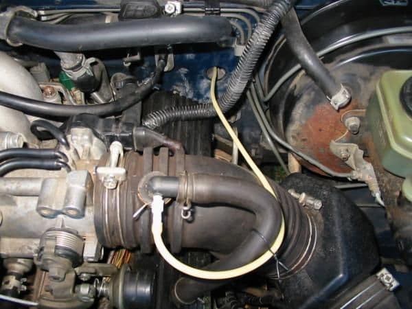
The airbox temperature probe routed through the air box inlet (red arrow).

The forward air stream temperature probe about 12" in front of the headlight. This is my best guess for the location of the undisturbed air stream.

Another view of the forward air stream temperature probe.

The probe wires are captured behind the rubber hood bumpers to keep them from flying loose.
Wire routing continues just under the quarter panel and behind the weather seal (white arrows).

Masking tape keeps the probe's wires from moving around.

The instruments ready to display data. On the left are two Taylor Indoor/Outdoor thermometers (model #1522), and on the right is my DIY slack-tube manometer.

The forward probe's readout is on the left labeled "FWD." On the right is the air box's probe readout labeled "Airbox." The top row of numbers indicate the cab's temperature as the control group. I'll use this group only to complete the gage R&R study to understand the variability of the thermometers. The lower left number is the air stream temperature. The lower right number is the air box temperature. Note: the units read as Celsius because I didn't change mode after I put the batteries in the for pic.

The manometer. The adjustable ruler's "zero point" is positioned at the meniscus (blue arrow). Negative pressure in the intake will cause the meniscus to climb higher. In a perfect world, the meniscus would stay at zero because there would be no restriction in the intake, with the engine breathing freely.

The next phase is more fun...data collection! (because we all need good data to make smart decisions.) Since I don't have a tach (yet).
 I'll have to use mph as an independent variable. Some questions that I'd like answers for are:
After conducting today's instrument test-run, I noted some interesting things. First, while at speed, the air box temp. eventually cooled to only a degree or two less than the air stream forward (this effect took awhile, 3~6 minutes or so depending on grade and engine rpm.)
Second, while waiting in traffic, e.g., at a light, the air box temp. increased to values much greater than ambient, and at one point less than 130�F. (This surprised me as I didn't expect the value would climb that high.)
Last, while exiting I-5 for SeaTac airport, I had the opportunity to downshift to 3rd gear, 2nd gear; and floor the pedal and hold it. As the engine topped-out, I noted that the manometer indicated about 6~7 inWC. This value is the rough number for the total restriction for my intake setup, and suggests possible opportunity for improvement(s).
A subsequent investigation may be to find out which component comprises the majority of the restriction. According to the Autospeed.com articles, that author found that the MAF was the culprit. Naturally, I'd be interested to confirm what the critter is in my own intake system...and eliminate it.
Stay tuned Guys...it's about to get interesting.
The airbox temperature probe routed through the air box inlet (red arrow).
The forward air stream temperature probe about 12" in front of the headlight. This is my best guess for the location of the undisturbed air stream.
Another view of the forward air stream temperature probe.
The probe wires are captured behind the rubber hood bumpers to keep them from flying loose.
Wire routing continues just under the quarter panel and behind the weather seal (white arrows).
Masking tape keeps the probe's wires from moving around.
The instruments ready to display data. On the left are two Taylor Indoor/Outdoor thermometers (model #1522), and on the right is my DIY slack-tube manometer.
The forward probe's readout is on the left labeled "FWD." On the right is the air box's probe readout labeled "Airbox." The top row of numbers indicate the cab's temperature as the control group. I'll use this group only to complete the gage R&R study to understand the variability of the thermometers. The lower left number is the air stream temperature. The lower right number is the air box temperature. Note: the units read as Celsius because I didn't change mode after I put the batteries in the for pic.
The manometer. The adjustable ruler's "zero point" is positioned at the meniscus (blue arrow). Negative pressure in the intake will cause the meniscus to climb higher. In a perfect world, the meniscus would stay at zero because there would be no restriction in the intake, with the engine breathing freely.
The next phase is more fun...data collection! (because we all need good data to make smart decisions.)
Since I don't have a tach (yet). I'll have to use mph as an independent variable. Some questions that I'd like answers for are:- What is the operating temperature range of the OEM air box, and how does it relate to the undisturbed air stream temperature? Is the difference statistically significant? What is the real-world significance?
- What is the total restriction value in the OEM intake system under real-time driving conditions? (With K&N drop-in filter.) Is any difference statistically significant? What is the real-world significance?
After conducting today's instrument test-run, I noted some interesting things. First, while at speed, the air box temp. eventually cooled to only a degree or two less than the air stream forward (this effect took awhile, 3~6 minutes or so depending on grade and engine rpm.)
Second, while waiting in traffic, e.g., at a light, the air box temp. increased to values much greater than ambient, and at one point less than 130�F. (This surprised me as I didn't expect the value would climb that high.)
Last, while exiting I-5 for SeaTac airport, I had the opportunity to downshift to 3rd gear, 2nd gear; and floor the pedal and hold it. As the engine topped-out, I noted that the manometer indicated about 6~7 inWC. This value is the rough number for the total restriction for my intake setup, and suggests possible opportunity for improvement(s).
A subsequent investigation may be to find out which component comprises the majority of the restriction. According to the Autospeed.com articles, that author found that the MAF was the culprit. Naturally, I'd be interested to confirm what the critter is in my own intake system...and eliminate it.
Stay tuned Guys...it's about to get interesting.
08-20-2013, 09:30 PM
#44
Registered User
Thread Starter
Join Date: Jun 2013
Location: Texas
Posts: 232
Likes: 0
Received 0 Likes
on
0 Posts
well folks still waiting for my s&b... i will upload pics when its all said and done! it'll be on my doorstep thursday evening...plan on routing a hose to intake hole from headlight...still wondering about a waterdeflector of some sort not that it matters much because I donty usually go crazy like that but still want somethin to block it out
08-20-2013, 09:40 PM
#45
Registered User
New Stuff!
well folks still waiting for my s&b... i will upload pics when its all said and done! it'll be on my doorstep thursday evening...plan on routing a hose to intake hole from headlight...still wondering about a waterdeflector of some sort not that it matters much because I donty usually go crazy like that but still want somethin to block it out
Exciting! Can't wait to hear your info. on your new intake!
08-20-2013, 09:58 PM
#46
Registered User
Thread Starter
Join Date: Jun 2013
Location: Texas
Posts: 232
Likes: 0
Received 0 Likes
on
0 Posts
me either. I like the K&N i do but im with alot of other people agreements as not really getting cold air but heated air from engine especially here in south texas where its 110 and hotter... Ill notice a difference if my trucks running better, after all no man knows his truck like the man who put blood, sweat, & tears fixing up his ride... just saying... also love the way your testing it skipper, cant wait for true results
08-20-2013, 11:45 PM
#47
Registered User

A subsequent investigation may be to find out which component comprises the majority of the restriction. According to the Autospeed.com articles, that author found that the MAF was the culprit. Naturally, I'd be interested to confirm what the critter is in my own intake system...and eliminate it.
Stay tuned Guys...it's about to get interesting.
Stay tuned Guys...it's about to get interesting.
My thoughts on intake restrictions are as follows just on the to chamber end (in order of restriction) -- what's below is covered in more detail recently here too btw https://www.yotatech.com/forums/f116...polish-271601/ :
1) is the stock headlight air scoop holes/setup -- that's why I added some add'l holes as linked previously in this forum. The headlights air scoops/frame on the drivers side (same as ours) were created for the 4 cylinder diesels and the passenger side is identical setup and where the 4cylinder 22re intakes. Both have smaller displacements and need less air flow than the 3vze.
2) next is probably the stock AFM (do the supra/camry swap but add a wideband 02 sensor to do it right, we don't have a MAF). Have some notes on the #s here: https://www.yotatech.com/forums/f88/.../#post52108877
3) third is the ISR bend (both from a heating intake air and airflow disruption perspective) -- Edit: actually this probably falls after the heads/valves, but since it's so cheap and easy, I'm leaving it here.
4) fourth is the factory heads and undersized valves (if doing new heads/valves, you should really do performance cams to match and get maximum bang)
5) next is the throttle body
6) next is the plenum design/plenum porting (might as well add in upper intake too)
7) last is the stock filter setup
But the exhaust on our rigs is a dog even without an increase air flow on the top end flow, so invest $ there first before spending serious $ on intake mods...
And if spending money to do all the mods to optimize the 3vze, you could have paid for a 3.4 5vzfe swap that gets better mpg, has more power, and is generally a better engine w/ all of intake stuff you'd "fix" already being corrected on the engine. That's why I personally am only interested in no/low cost mods on the 3vze as I put $ away towards that goal...
That's my opinion anyways.

Last edited by RSR; 08-20-2013 at 11:50 PM.
08-21-2013, 12:30 AM
#48
Registered User
Thread Starter
Join Date: Jun 2013
Location: Texas
Posts: 232
Likes: 0
Received 0 Likes
on
0 Posts
Very agreeable but considering its hard to hold on to that amount of money all at once and being I need this thing running top shape all I can and have no alternate vehicle for work I do what helps for now. That and I have no friends that are knowledgeable enough to even help me attempt to do that and all the mechanics here are sneaky crooks. Besides not many people who a 3vze original from 89 that's never had a head gasket job done and barely breaking 165k and going very strong at speeds going 85+ lol. That and even though most people think it's crap engine because we all know it can be better but for me it'll work just fine I'm happy with it although with everything stock omg what a piece lol
08-21-2013, 09:40 AM
#49
Registered User
Scruss -- not criticizing anyone's choices there. That list is just my thoughts on the most restrictive part of the intake in descending order (biggest to smallest) of restriction.
Fix this, then what's next biggest dog, etc. Obviously, if you fix/upgrade anything out of my assumed order, you'll still probably see a benefit, but without fixing stuff that's a bigger cause of restriction/higher up the list, you're going to be limited by the primary point of restriction in the intake that's currently the biggest dog... And Skipper will almost certainly prove some of my assumptions wrong with his test too.
Take the new heads, valves and cams. In addition to new heads or machining current, new cams or regrinding current, and oversized valves, you also essentially have to do a headgasket job to get everything installed, which requires add'l machining and specialized labor and if you have your engine torn down that far, should you go ahead and rebuild your lower engine too?. The head portion makes it easily a $2k job and add the lower engine and you're easily at $3k-$4k, which would easily pay for a rebuilt 5vzfe, and almost nearly to completely pay for someone else to install it (toyonlyswaps.com advertises 5vzfe manuals w/ current r150 trannies installed for $3500 (equivalent to 7 months or less of a new car payment). My point is merely figure out where you want to spend your money before you start down the rabbit's hole of modding the 3vze for maximum power... Because if you're going to be spending that cash anyways, just make sure you don't have to spend it more than once to get where you ultimately want/need to be...
I too am happy with my slightly modded 3vze that just hit 150k miles, but I really would like power and if I can do that and get better mileage and arguably better reliability by going with the 5vzfe, then that's a compelling case to go that route... Apologies for the tangent. Just what I've been thinking on how far it's prudent for me personally to upgrade the 3vze -- and I am very intrigued by your S&B and the injectors you're currently running for instance as mods within my "prudent" budget for upgrading my current engine while slowly saving towards my next (and the next isn't a financial priority for me or my wife right now -- it's probably 3-5 years off...).
Last edited by RSR; 08-21-2013 at 09:47 AM.
08-21-2013, 09:52 AM
#50
Registered User
Looking forward to both aspects of this thread.
My thoughts on intake restrictions are as follows just on the to chamber end (in order of restriction) -- what's below is covered in more detail recently here too btw https://www.yotatech.com/forums/f116...polish-271601/ :
1) is the stock headlight air scoop holes/setup -- that's why I added some add'l holes as linked previously in this forum. The headlights air scoops/frame on the drivers side (same as ours) were created for the 4 cylinder diesels and the passenger side is identical setup and where the 4cylinder 22re intakes. Both have smaller displacements and need less air flow than the 3vze.
2) next is probably the stock AFM (do the supra/camry swap but add a wideband 02 sensor to do it right, we don't have a MAF). Have some notes on the #s here: https://www.yotatech.com/forums/f88/.../#post52108877
3) third is the ISR bend (both from a heating intake air and airflow disruption perspective) -- Edit: actually this probably falls after the heads/valves, but since it's so cheap and easy, I'm leaving it here.
4) fourth is the factory heads and undersized valves (if doing new heads/valves, you should really do performance cams to match and get maximum bang)
5) next is the throttle body
6) next is the plenum design/plenum porting (might as well add in upper intake too)
7) last is the stock filter setup
But the exhaust on our rigs is a dog even without an increase air flow on the top end flow, so invest $ there first before spending serious $ on intake mods...
And if spending money to do all the mods to optimize the 3vze, you could have paid for a 3.4 5vzfe swap that gets better mpg, has more power, and is generally a better engine w/ all of intake stuff you'd "fix" already being corrected on the engine. That's why I personally am only interested in no/low cost mods on the 3vze as I put $ away towards that goal...
That's my opinion anyways.
I like your thinking! That's why I've setup this measuring/data collection project to resist jumping to solutions before understanding the need to have a solution. And yes, I'm not going to spend any of my scarce $$$ if I don't have a d(*^# good reason to. My priority is to prolong the efficient operation of my rig. So if I can improve the mpg and/or HP with very minor or low-cost mods, then I might just do that. The last time I pulled mpg figures from my maintenance log, I was getting 19-20 mph highway; and I'd like to keep that as the minimum. Someone here on the forum said that mpg depends a lot on how you drive, and I tend to accept that straight-on. I like these kind of projects, but I don't want to waste my time either.
Well, let's learn something already!
 08-21-2013, 10:56 AM
#51
Registered User
Thread Starter
Join Date: Jun 2013
Location: Texas
Posts: 232
Likes: 0
Received 0 Likes
on
0 Posts
Scruss -- not criticizing anyone's choices there. That list is just my thoughts on the most restrictive part of the intake in descending order (biggest to smallest) of restriction.
Fix this, then what's next biggest dog, etc. Obviously, if you fix/upgrade anything out of my assumed order, you'll still probably see a benefit, but without fixing stuff that's a bigger cause of restriction/higher up the list, you're going to be limited by the primary point of restriction in the intake that's currently the biggest dog... And Skipper will almost certainly prove some of my assumptions wrong with his test too.
Take the new heads, valves and cams. In addition to new heads or machining current, new cams or regrinding current, and oversized valves, you also essentially have to do a headgasket job to get everything installed, which requires add'l machining and specialized labor and if you have your engine torn down that far, should you go ahead and rebuild your lower engine too?. The head portion makes it easily a $2k job and add the lower engine and you're easily at $3k-$4k, which would easily pay for a rebuilt 5vzfe, and almost nearly to completely pay for someone else to install it (toyonlyswaps.com advertises 5vzfe manuals w/ current r150 trannies installed for $3500 (equivalent to 7 months or less of a new car payment). My point is merely figure out where you want to spend your money before you start down the rabbit's hole of modding the 3vze for maximum power... Because if you're going to be spending that cash anyways, just make sure you don't have to spend it more than once to get where you ultimately want/need to be...
I too am happy with my slightly modded 3vze that just hit 150k miles, but I really would like power and if I can do that and get better mileage and arguably better reliability by going with the 5vzfe, then that's a compelling case to go that route... Apologies for the tangent. Just what I've been thinking on how far it's prudent for me personally to upgrade the 3vze -- and I am very intrigued by your S&B and the injectors you're currently running for instance as mods within my "prudent" budget for upgrading my current engine while slowly saving towards my next (and the next isn't a financial priority for me or my wife right now -- it's probably 3-5 years off...).
Fix this, then what's next biggest dog, etc. Obviously, if you fix/upgrade anything out of my assumed order, you'll still probably see a benefit, but without fixing stuff that's a bigger cause of restriction/higher up the list, you're going to be limited by the primary point of restriction in the intake that's currently the biggest dog... And Skipper will almost certainly prove some of my assumptions wrong with his test too.
Take the new heads, valves and cams. In addition to new heads or machining current, new cams or regrinding current, and oversized valves, you also essentially have to do a headgasket job to get everything installed, which requires add'l machining and specialized labor and if you have your engine torn down that far, should you go ahead and rebuild your lower engine too?. The head portion makes it easily a $2k job and add the lower engine and you're easily at $3k-$4k, which would easily pay for a rebuilt 5vzfe, and almost nearly to completely pay for someone else to install it (toyonlyswaps.com advertises 5vzfe manuals w/ current r150 trannies installed for $3500 (equivalent to 7 months or less of a new car payment). My point is merely figure out where you want to spend your money before you start down the rabbit's hole of modding the 3vze for maximum power... Because if you're going to be spending that cash anyways, just make sure you don't have to spend it more than once to get where you ultimately want/need to be...
I too am happy with my slightly modded 3vze that just hit 150k miles, but I really would like power and if I can do that and get better mileage and arguably better reliability by going with the 5vzfe, then that's a compelling case to go that route... Apologies for the tangent. Just what I've been thinking on how far it's prudent for me personally to upgrade the 3vze -- and I am very intrigued by your S&B and the injectors you're currently running for instance as mods within my "prudent" budget for upgrading my current engine while slowly saving towards my next (and the next isn't a financial priority for me or my wife right now -- it's probably 3-5 years off...).
08-21-2013, 07:19 PM
#52
Registered User
My S&B intake will be here this evening and that my friend means I'll have pics uploaded of my K&N>S&B Conversion... Although I still plan on directing airflow to the intake so I'll see what I cant figure out but I think I have a good Idea I'll have to wait for the kit to get her before I can say...After all the way I have it now directs colder air to the filter when rolling down the road.. however thats only when moving down the road... I wanna figure out a way to make forced air go thru thye intake at a stop...thoughts?? cant wait for S&B to be here later
Forced induction is typically super or turbocharged vehicles. There are some tornado or vortex fans or something of the sort that supposedly add a little boost, but probably not worth the effort. Your engine will pull in air naturally.
08-22-2013, 07:06 AM
#55
Registered User
Thread Starter
Join Date: Jun 2013
Location: Texas
Posts: 232
Likes: 0
Received 0 Likes
on
0 Posts
lol yea its original one hasn't gave me no problems at all so cant complain.. I cant wait for this dang S&B Intake to get here... I've also been brainstorming some ideas on making this setup more efficient...stay tuned everybody...
Last edited by Scrussanation; 08-22-2013 at 07:11 AM.
08-22-2013, 05:15 PM
#57
Registered User
Thread Starter
Join Date: Jun 2013
Location: Texas
Posts: 232
Likes: 0
Received 0 Likes
on
0 Posts
Original K&N Intake

Hmmmm look at all the goodies inside...

Contents of Package...

Unhook battery...

unfasten K&N filter clamp...

Remove the filter...

Filter Comparison...

Unhook distributor spark plug...

tuck under wires near cap so they stay out of the way...

Remove VAFM meter plug.... i gettem confused you know what I mean...

unplug and move out of way...

loosten screw on main intake elbow...

remove the one screw for the coolant reservoir and other 2 screws that held the main cover over the headlight...

what it should look like after you remove remainding...k&N mounts that your removing...

install circular piece with foam gasket onto filter box...


fasten the piece like so...

screw all holes for the piece nice and firm, but not to where it breaks lol

its a 10mm if ya was wondering...

I've got breather filters and thats why I never used this hole in my old K&N, so I guess I'll just transfer over the plug..


you may want to have lil threadtape to make sure airtight seal..


install long bracket on side in picture with one of the three nuts with washers provided....

and the smaller one on this side...

Drop the box in and line her up to roughly match...

re install coolant reservoir...

attach air flow meter to box similar to way k&n did it and you will be useing the same hardware you had before...


Now Mount those brackets we installed on box earlier, their will be factory holes already...


Plug air flow meter back in...

sometimes easier if you put retaining clip on plug before you slide it on...


install distributor cap wire back in..

refasten intake clamp...

I found you kinda have to wiggle it in theough the top in a weird way but itlls go eventually..


fasten filter clamp...

get glass and screws ready!!!


self explanatory..


FINISHED!!!!


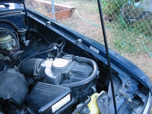
where it draws air from directly behind headlight...


Keep in mind this is my setup for it, you may have resonator boxes still there or whatever the case is but this was mine... Now the real test comes and thats to drive!!!
Hmmmm look at all the goodies inside...
Contents of Package...
Unhook battery...
unfasten K&N filter clamp...
Remove the filter...
Filter Comparison...
Unhook distributor spark plug...
tuck under wires near cap so they stay out of the way...
Remove VAFM meter plug.... i gettem confused you know what I mean...
unplug and move out of way...
loosten screw on main intake elbow...
remove the one screw for the coolant reservoir and other 2 screws that held the main cover over the headlight...
what it should look like after you remove remainding...k&N mounts that your removing...
install circular piece with foam gasket onto filter box...
fasten the piece like so...
screw all holes for the piece nice and firm, but not to where it breaks lol
its a 10mm if ya was wondering...
I've got breather filters and thats why I never used this hole in my old K&N, so I guess I'll just transfer over the plug..
you may want to have lil threadtape to make sure airtight seal..
install long bracket on side in picture with one of the three nuts with washers provided....
and the smaller one on this side...
Drop the box in and line her up to roughly match...
re install coolant reservoir...
attach air flow meter to box similar to way k&n did it and you will be useing the same hardware you had before...
Now Mount those brackets we installed on box earlier, their will be factory holes already...
Plug air flow meter back in...
sometimes easier if you put retaining clip on plug before you slide it on...
install distributor cap wire back in..
refasten intake clamp...
I found you kinda have to wiggle it in theough the top in a weird way but itlls go eventually..
fasten filter clamp...
get glass and screws ready!!!
self explanatory..
FINISHED!!!!
where it draws air from directly behind headlight...
Keep in mind this is my setup for it, you may have resonator boxes still there or whatever the case is but this was mine... Now the real test comes and thats to drive!!!
08-22-2013, 06:42 PM
#58
Registered User
Thread Starter
Join Date: Jun 2013
Location: Texas
Posts: 232
Likes: 0
Received 0 Likes
on
0 Posts
oh yeah big difference from k&n to S&B... main difference thats helping is the enclosed airbox.. I noticed when my rpms were around 3500 seemed alot more power was available... I was passing people uphill with no momentum from any downhill in 5th gear... yes I'm geared for bigger tires but when I went from 35"s to 37"s I did lose some gettup I had previously but after I changed this setup out I've got it back like I had 35's again if not more... I still need to drill some holes out like you did though that should net an improvement by itself... overall I'm very pleased with the setup... I like the fact I'm getting less hot air from the engine like I was... for some reason its so much hotter under the engine area you can hear a big difference in the way the truck idles when hot... It ran fine by all means but just somethin was off in those hot days.. ready to do another test run at peak of day when its the hottest... especially here in texas it should show some difference lol
08-22-2013, 10:22 PM
#59
Registered User
oh yeah big difference from k&n to S&B... main difference thats helping is the enclosed airbox.. I noticed when my rpms were around 3500 seemed alot more power was available... I was passing people uphill with no momentum from any downhill in 5th gear... yes I'm geared for bigger tires but when I went from 35"s to 37"s I did lose some gettup I had previously but after I changed this setup out I've got it back like I had 35's again if not more... I still need to drill some holes out like you did though that should net an improvement by itself... overall I'm very pleased with the setup... I like the fact I'm getting less hot air from the engine like I was... for some reason its so much hotter under the engine area you can hear a big difference in the way the truck idles when hot... It ran fine by all means but just somethin was off in those hot days.. ready to do another test run at peak of day when its the hottest... especially here in texas it should show some difference lol
I can plainly see the difference in air pickup point opening size. The OEM air box opening has about a 2"~3" diameter with a venturi shape (IIRC) while yours looks like a 2"x4" square opening. Wouldn't it be something if it were easy to move the headlight so we could duct the opening directly to the front of the grill? Better yet, a venturi--shaped inlet.
I'd really like to know the pressure drop in your new setup. Do you have any thoughts on measuring it?
08-22-2013, 10:51 PM
#60
Registered User
Thread Starter
Join Date: Jun 2013
Location: Texas
Posts: 232
Likes: 0
Received 0 Likes
on
0 Posts
Nice sequence of pics and explanatory notes! I'm curious as to why S&B didn't shape the filter adapter from round into square in a venturi-style. (I'm going to presume that they measured the air flow resistance to be minuscule at that point.)
I can plainly see the difference in air pickup point opening size. The OEM air box opening has about a 2"~3" diameter with a venturi shape (IIRC) while yours looks like a 2"x4" square opening. Wouldn't it be something if it were easy to move the headlight so we could duct the opening directly to the front of the grill? Better yet, a venturi--shaped inlet.
I'd really like to know the pressure drop in your new setup. Do you have any thoughts on measuring it?


