
4Crawler BJ/Rear Coil Spacer’s…The WriteUP
 01-12-2010, 06:06 PM
#1
Registered User
Thread Starter
Join Date: Apr 2008
Location: Glendale AZ
Posts: 292
Likes: 0
Received 0 Likes
on
0 Posts
4Crawler BJ/Rear Coil Spacer’s…The WriteUP
Purpose:
Don’t know how to install spacers? Hopefully this helps.
The truck:
91’ 22RE 5spd 4WD SR5 4Runner
Stuff Installed:
1.5” SDORI/4Crawler BJ (Ball Joint) Spacers, IFS Diff Drop Deluxe Kit, Energy Suspension’s Black Polyurethane Sway Bar Bushing kit (Front Part # 8.5114G), (Rear Part # 8.5115G), MOOG ball joints. 4Crawler 2” Rear Coil Spring Spacers, 4Crawler 4” LSPV (Load Sensing Proportioning Valve) Relocation Bracket, 4Crawler 4” Track Bar (Pan Hard Rod) Deluxe Drop Bracket kit. Crown 26” clear Male-Female Rear Brake Line from Marlin Crawler. Aisin Manual Locking Hubs (86’-95’).
Depending on the shocks that you have you may or may not need longer shocks after the install of the spacers.
I’ll start with the front end first…
Tools needed: Some type of cutter or grinder to cut the upper control arms, metric sockets (shallow and deep), ratchets, various socket extensions, torque wrench (I used a 3/8” and ˝”), metric hex bit socket (6mm), open end/box wrenches, hammer, pry bar, penetrating lubricant, patience, beverages of choice.
Optional: Air Compressor, air tools, impact sockets, sharpie pen, tape-measure, ruler, spray paints, sand paper of various grits, #00 steel wool.
BJ Spacer’s:
The BJ Spacers are just blocks of milled aluminum that fit in-between the upper ball joint and upper control arm, hence the name. Once installed the upper control arm retains its original angle because it has the tension of the torsion bar always pushing down on it, just as it always had. Because of this any spacer mounted in between the upper ball joint and upper control arm will lift the front end of the truck as tall as the spacer is (usually, give or take a few…). This happens because you effectively push the lower control arm down as much as the spacer is tall, which in turn drops the original placement of the hub/knuckle/spindle shaft (further south of the fender) which allows the truck to sit higher.
I chose to use the 1.5” BJ Spacers that Rodger Brown from 4Crawler.com sells. Rodger actually sells the spacers made by SDORI (San Diego Off-Road Innovations). Paired along with 2” polyurethane Rear Coil Spring Spacers (also from 4Crawler) I thought that this would be a good but mild lift for my 4Runner, giving me a total of 2” of lift overall.
After receiving them in the mail I opted to add an extra layer of protection to them with a coat of RUST-OLEUM Gloss Clear Coat. This came after a light rub down with #00 steel wool, which also really polished them up. After a few sprays of brake cleaner to clean them off I gave them two coats each of the clear. Although this isn’t the absolute proper way to prep and apply paint to an aluminum surface they have looked shiny ever since instead of turning to the dull oxidized aluminum look. After the clear coat was cured it was time to install these milled paper weights.
Refer to Rodger’s install page for help and tips,
http://www.4crawler.com/4x4/ForSale/...er_HowTo.shtml
After jacking the truck up and placing it on jack stands I first started by using PB Blaster on every fastener that I knew I was going to remove. Let it soak for a few minutes. Then I proceeded to remove the front shock. One thing to consider is that you might want to change your ball joints out if needed at this time since you have everything apart for this job anyway.
I bought a set of MOOG ball joints. At least for my 91’ 4Runner, these are the MOOG part numbers.
(Upper Ball Joint # K9482, Lower Ball Joint # K9519).
Passenger and driver side will use the same ball joints, so two of each.
((Upper ball joint to upper control arm, 13mm socket (6mm Hex bit socket if you install the BJ spacers with the included hardware), torque to 25 ft. Ibs. 27mm socket for stud to steering knuckle, torque to 105 ft. Ibs. Included Zirk fitting, 8mm socket, hand tighten snug. --- Lower ball joint to steering knuckle, 17mm socket torque to 43 ft. Ibs. 27mm socket for stud to lower control arm, torque to 105 ft. Ibs. Included Zirk fitting, 3/8” open end wrench, hand tighten snug.))
I first removed the sway bar link nuts at the lower control arm (14mm deep socket) on both sides so the lower arms would drop down far enough for the install.
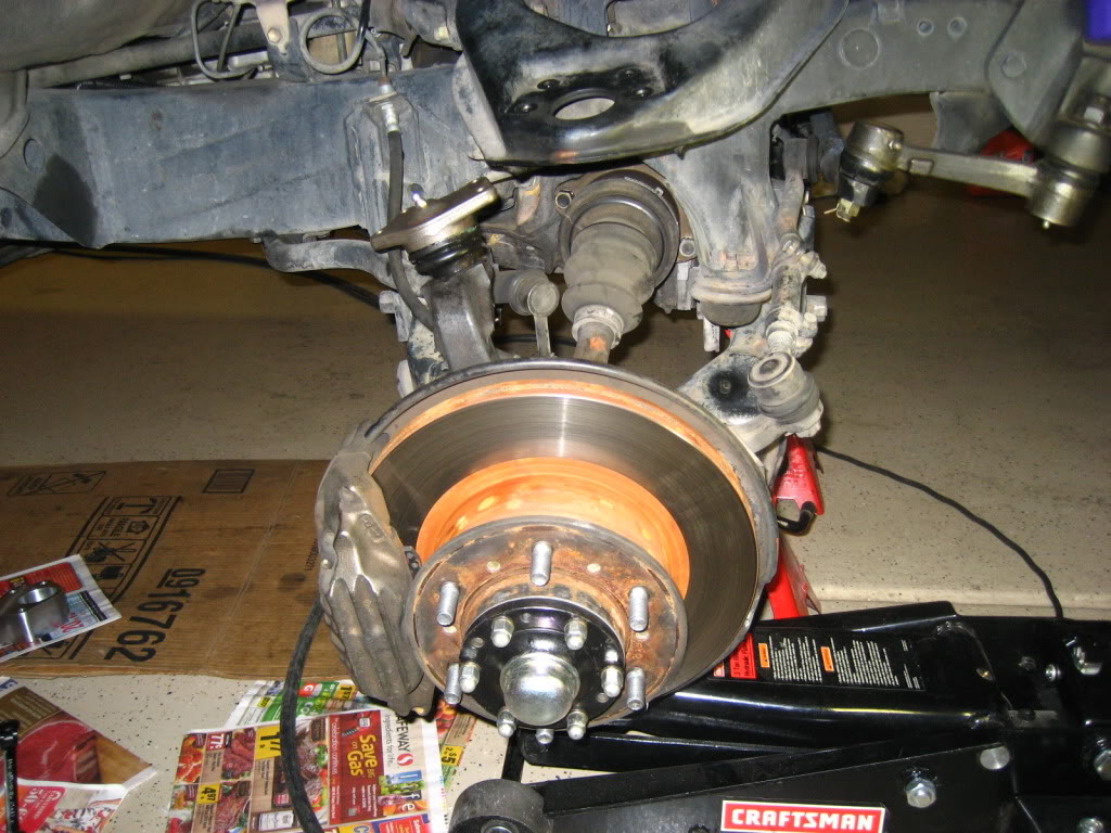
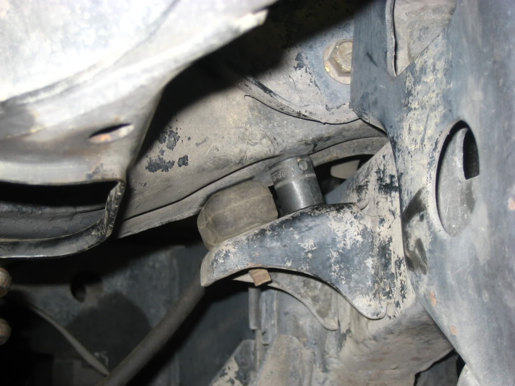
Before removing the upper ball joint from the upper control arm I placed a Snap-On 3/8 drive 17mm impact socket between the upper control arm and upper bump-stop mount. You can do this by jacking up the lower control arm until you have enough space present between the upper control arm and upper bump stop mount. After that simply release the jack and the upper control arm will be pushing down/resting on the socket.
Why you ask? As described on Rodgers page it is helpful to use a type of “wedge” to have the upper control arm sit higher then stock so you will have room to get under and make the appropriate cut in the arm so the BJ spacer will fit.
I used a socket because I didn’t really have anything else lying around in my garage that I could have used. I chose to use an impact socket as they are stronger than standard chrome sockets.
Below is a closer look at the socket that I used to help the upper control arm sit higher.
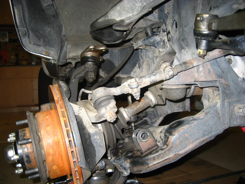
I then removed the ball joint from the arm. Although you can’t see it pictured below I left my floor jack under the lower arm to help support the weight of everything before I actually removed the bolts and nuts. Once all the bolts were off I slowly lowered the jack to separate the ball joint from the upper arm.
Do not let the arm lower itself as low as it would want to go; leaving the jack under the lower control arm will help the CV axle from separating at the joints/boots. If this happens, as it did to me you will have to gently turn the brake rotor/axle back and forth while pushing inward until the CV joint set’s back in place. You can tell because the CV boot will look like how it’s supposed to instead of stretched out and kinked.
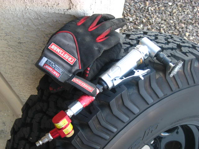
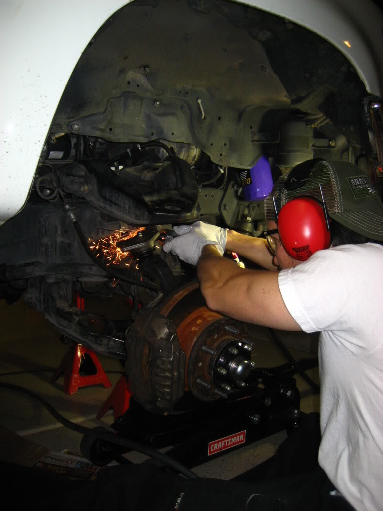
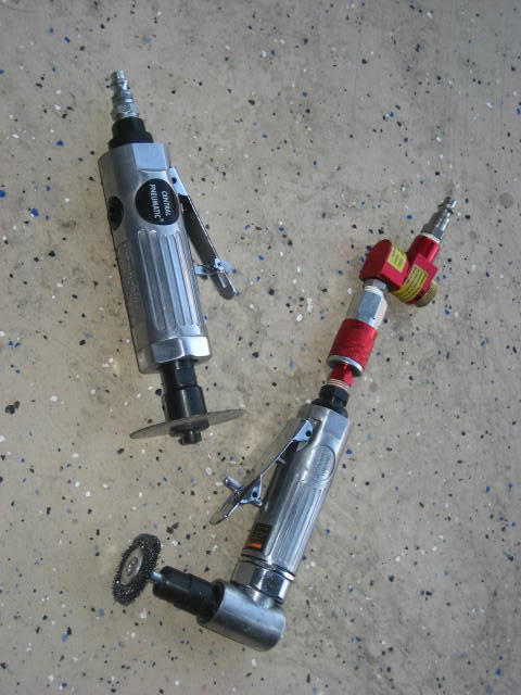
Because I already had a 30 gallon Craftsman Compressor I chose to use a high speed air cutter to do my cutting of the upper control arm. I went to the highest quality tool store available in all the land…Harbor Freight. Best $7 I ever spent and amazingly the air cutter still works after this job was completed! Sure put my compressor to work; this thing uses a lot of air.
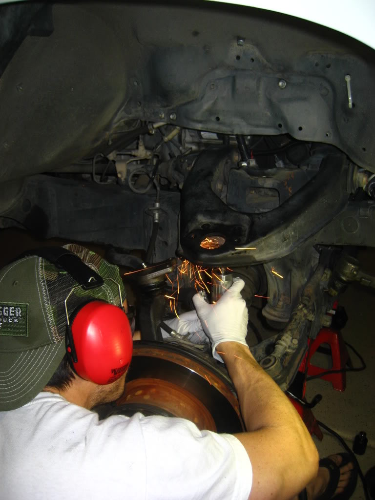
Don’t forget to wear safety glasses when cutting because the sparks will be flying. I also picked up a pair of ear muffs at Harbor Freight. Spending an extra $5 saved me from going deaf from the cutter and the compressor.
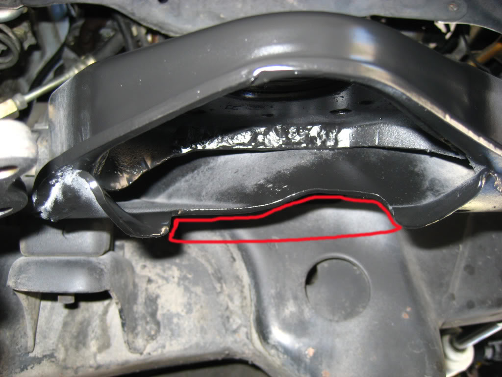
This picture above shows how much material I removed from the arm as depicted by the red border. As Rodger says on his install page, only remove as much as you need. This cut took me a couple of try’s to finish as I kept doing a fit check with the BJ spacer but I certainly did not want to butcher my upper arm either. It’s also a good idea to mark the areas you want to cut with a sharpie pen after making measurements.
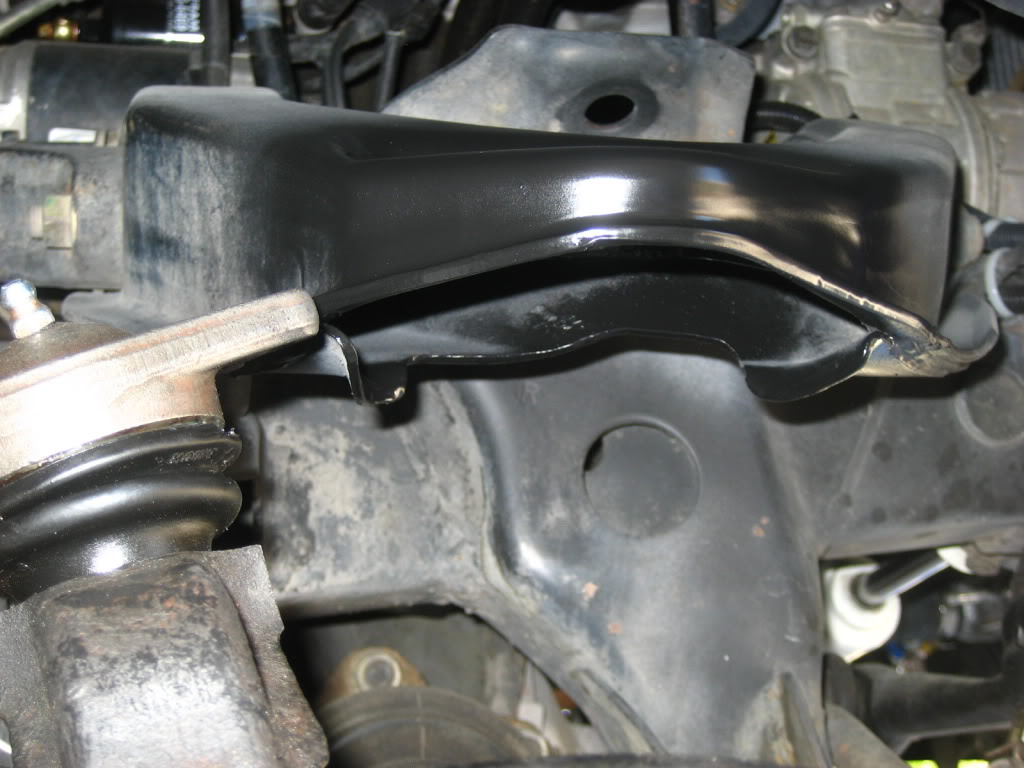
The shape of the cut is the way it is because of the shape of the BJ spacer and having enough clearance to get it inside the upper arm. Be patient and things will work better in the end. Now you can do it all over again on the opposite side upper control arm.
A couple swipes with the cutting wheel and some sand paper to knock off the rough edges and then a couple sprays of primer & flat black Rust-oleum. I highly recommend this to prevent corrosion later on.
Now it’s time to install the BJ spacers. This is an easy task as you will just use the new hardware provided in the kit. This consists of longer hex bolts which will require a 6mm hex bit socket, a set of lock nuts and regular nuts and washers. It took some juggling to get the spacer seated properly, I had to tug on the lower control arm at the same time trying to rest the BJ spacer on the ball joint and then getting everything under the lip of the arm.
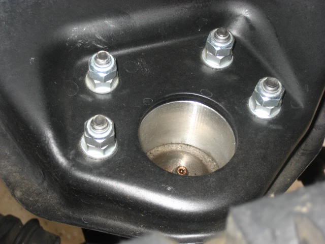
Don’t forget to mount the spacers with the weep holes/notches facing down! This is a drain to let any water out instead of sitting on top of the ball joint. If the water can’t drain then corrosion will occur.
Once in the arm simply bolt down. This is where I used a 3/8” drive 6mm hex bit socket on my 3/8” drive torque wrench. Torque regular nut (1/2”) and hex bolt to 25ft Ibs. Then snug the nylon lock nut (13mm) down on top of the regular nut. This will prevent the regular nut from backing off and coming loose in the future.
The next group of pictures below shows what it should look like after installed
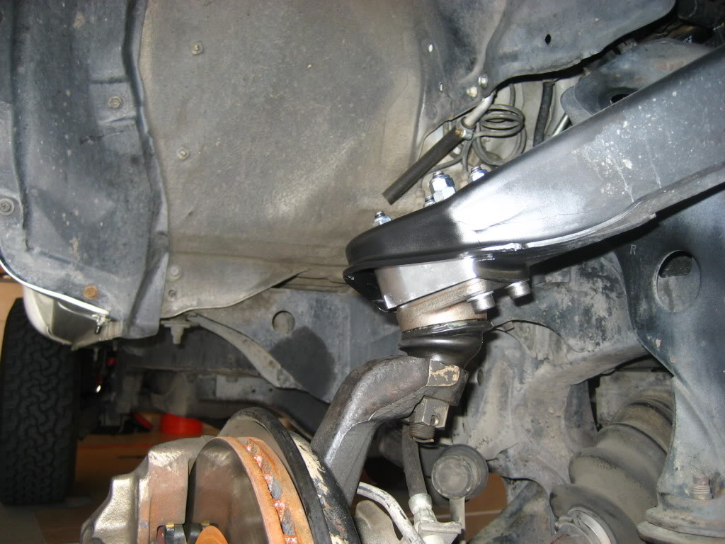
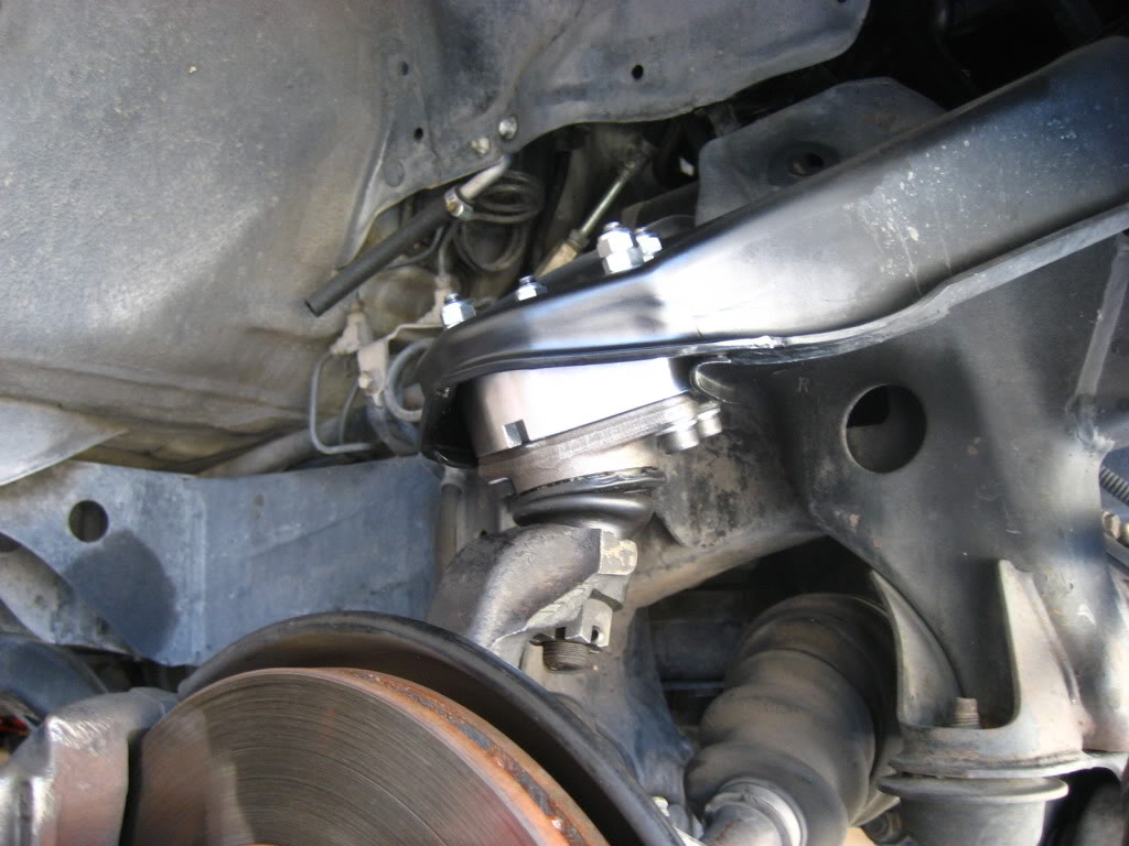
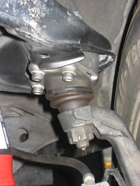
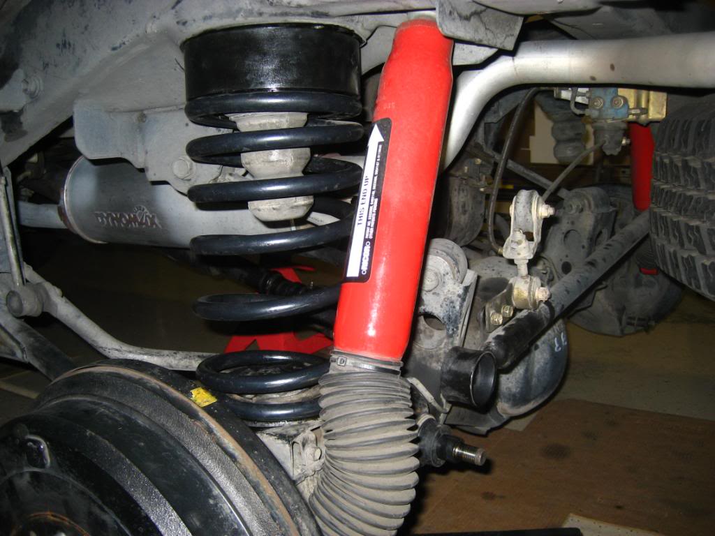
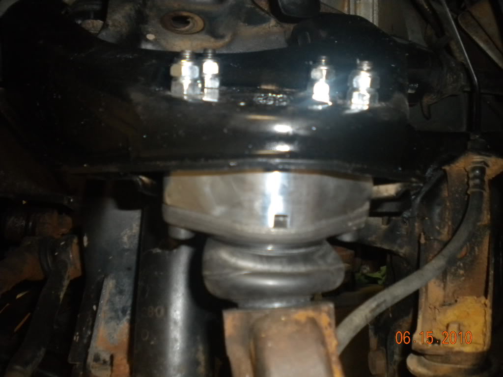
Below is a view from behind the front passenger tire looking up to the BJ spacer:
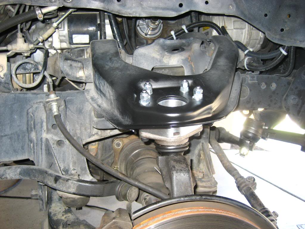
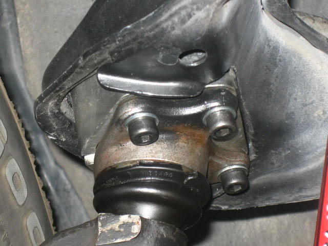
Below is a view from the front of the truck looking up to the passenger side BJ Spacer:
After the BJ spacers are installed you can put the front shock back on. This was also a good time for me to install the IFS Diff Drop Deluxe Kit, which includes 4Crawler’s 1” front sway bar drop kit and 1” front differential drop kit.
The sway bar drop kit that Rodger sells is nothing more than 1” spacers and it helps the sway bar retain its original angle and height in relation to the lower control arm after sitting lower now from the lift. Each spacer looks like milled Delrin to me. I chose to paint my spacers flat black to help blend in with the chassis.
Below is the front sway bar drop spacers and Energy Suspension polyurethane sway bar bushings:
After the paint cured I simply unbolted the stock sway bar mounts on the chassis and put the spacers in place. Since I had removed the sway bar mounts I also installed Energy Suspension’s Black Polyurethane Sway Bar Bushing kit (Part # 8.5114G). This kit includes 2 bushings for the sway bar and all the bushings and washers needed for the end links. It also includes a tube of Energy Suspensions Formula 5 grease for polyurethane bushings. The old stock rubber bushings were well past their life span. Visible cracks and chips in the rubber were present. I then bolted everything back up with the new and longer hardware provided.
Below is the new Energy Suspension polyurethane sway bar end link bushings:
I then attempted to install the 1” front differential drop kit to help alleviate the CV angles from becoming to steep due to the lift from the BJ spacers. You can find more information about this on 4Crawlers website.
Just like the BJ spacers this kit is also milled aluminum and just like what I did to the BJ spacers I did the same to theses. A couple swipes of steel wool and some clear coat. They shined up really well.
I then loosened the bolt on the front of the differential and then removed the 2 bolts, washers and nuts in the rear of the differential, all the time having my floor jack supporting the weight of the differential in the back near the driveshaft.
Once I lowered the differential with the jack I was able to slide the spacers in place but I ended up having a very difficult time getting the included longer bolt to go into the spacer on the passenger side. I just couldn’t get the differential and spacer to line up so the bolt could go through both of then and the hole in the chassis. I figured this was due to the fact that the spacer is as tall as it is and because the front of the differential is bolted closer to the passenger side instead of in the middle of the truck. This made pivoting the differential in the direction needed a lot more difficult compared to the drivers side. I had to use a pry bar on the front differential in order to line the holes up while trying to install the bolt with my other hand. This was not easy or fun.
As of now there is a lot of tension on that bolt. I could loosen the drivers side and it would probably fall out of the hole on it’s own but it won’t happen for the bolt on the passenger side. I tried searching for any problems like this that others may have encountered but I couldn’t find anything on this subject. It’s in now and seems to be working fine.
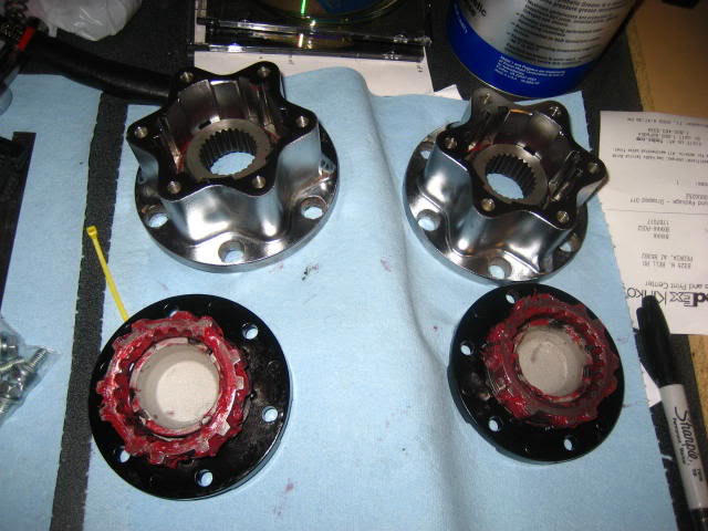
To further help the CV’s out I got my hands on a pair of Aisin Seiki Manual Locking Hubs off of eBay (if you’re not in a rush I suggest you roam the local junkyards as you can probably get them a lot cheaper).
Now my CV’s won’t be constantly spinning as I’m driving in 2wd. This helps to extend the life of the boot’s and CV joints. As far as I know these hubs will fit 4Runners from 86’- 95’. Before installing the hubs I shipped my free wheeling hub covers and control handles to Wabfab for powder coating and new gaskets. They did a great job and it looks brand new again. I did however have to remove some of the powder coating on the free wheeling hub cover tabs and control handle edges because the powder coating was too thick. Once removed I was able to install the handles into the covers.
There’s a lot of info on these hubs online. If you’re not familiar with these hubs and how they go together then here’s a few links below that I had to use to help me put them back together. Just take your time and it will work out. I had no knowledge of these hubs until they showed up on my doorstep and I started to tear them down. I also had to get a pair of internal/external ring pliers in order to work on these hubs. Got a pair of large Craftsman Professional from Sears with interchangeable tips, about $30.
http://www.off-road.com/trucks4x4/ar....jsp?id=399612
http://www.off-road.com/offroad/arti....jsp?id=399668
http://forum.ih8mud.com/79-95-toyota...b-rebuild.html
http://www.4x4wire.com/toyota/mainte...d/hub_rebuild/
Here’s the Toyota factory manual excerpt for the Aisin manual hubs in PDF format so you can download them to your computer. This is handy to have when you’re messing with them.
http://www.yankeetoys.org/Documents/AisinHubs.pdf
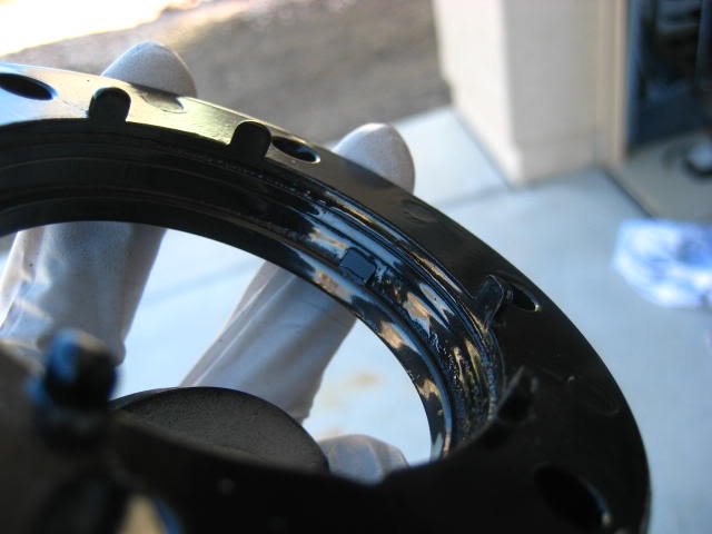
Above are the covers when they arrived to me from Wabfab. Below shows the tabs after they were lightly sanded using my Dremel. You can do these by hand with some sandpaper but it would take a lot longer.
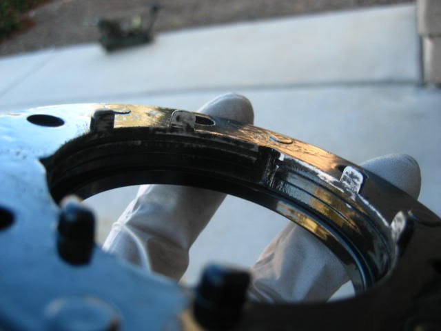
Below is the handle, the powder coating on the outer edge was a little to thick.
After lightly sanding with my Dremel.
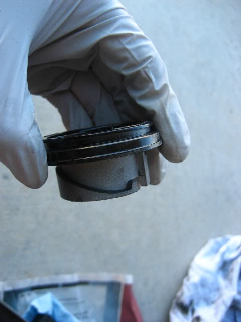
Hub body completely cleaned, re-greased and ready to be bolted on the hub with new hub gasket. Torque hub fasteners to 23 ft. Ibs.
Cover, handle and new star gasket ready to go on. Torque cover fasteners to 7 ft. Ibs.
Now the CV’s can rest. I also chose to use different hardware then the standard and stock 10mm socket size nuts and hex bolts.
This completed all the front end mods.
Rear Suspension…
I actually did the rear suspension first because I knew I couldn’t finish everything in 1 day and I use my truck everyday. I figured I would go with the jacked up hot rod look for a couple of days instead of an over exaggerated sagging rear end look by doing the BJ spacers first. The rear end actually took much longer then it should of. I didn’t order all the parts I needed at the same time, etc, etc…
Tools needed: Grinder to shave the tops of your coils (optional), metric sockets, ratchets, various socket extensions, torque wrench, breaker bar, ˝” impact gun (optional), spring compressor (optional), open end/box wrenches, flare nut wrenches for the brake line, drill for the 4” track bar drop bracket, ball peen hammer, dead blow hammer, come-along/hand winch, pry bar, penetrating lubricant and more patience.
First things first, don’t do what I did. Have all the tools that you need (get your hands on a come along/hand winch) and get yourself a longer rear brake line and the track bar drop bracket, also you might want to consider an LSPV relocation bracket as I ended up needing one. Spending $29 for the brake line before you begin the project will make the job more enjoyable and if you haven’t bled your brakes in awhile then you’ll hit 2 birds with one stone. Brake fluid does wear out.
I ordered my Male-Female rear brake line from Marlin Crawler. It’s made by Crown, supposed to be really good stuff and its 26” long, more then enough length for a coil spring spacer lift. There’s also 3 colors’ to choose from, blue red and clear. I went with the clear. The same goes for the track bar drop bracket and LSPV bracket, at least for me and my truck not having it when I needed it made things a lot more difficult. I was under the impression that because I was only lifting the truck 2” I would not need them. This turned out to be untrue. Very untrue.
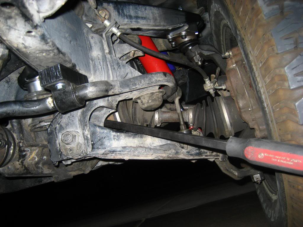
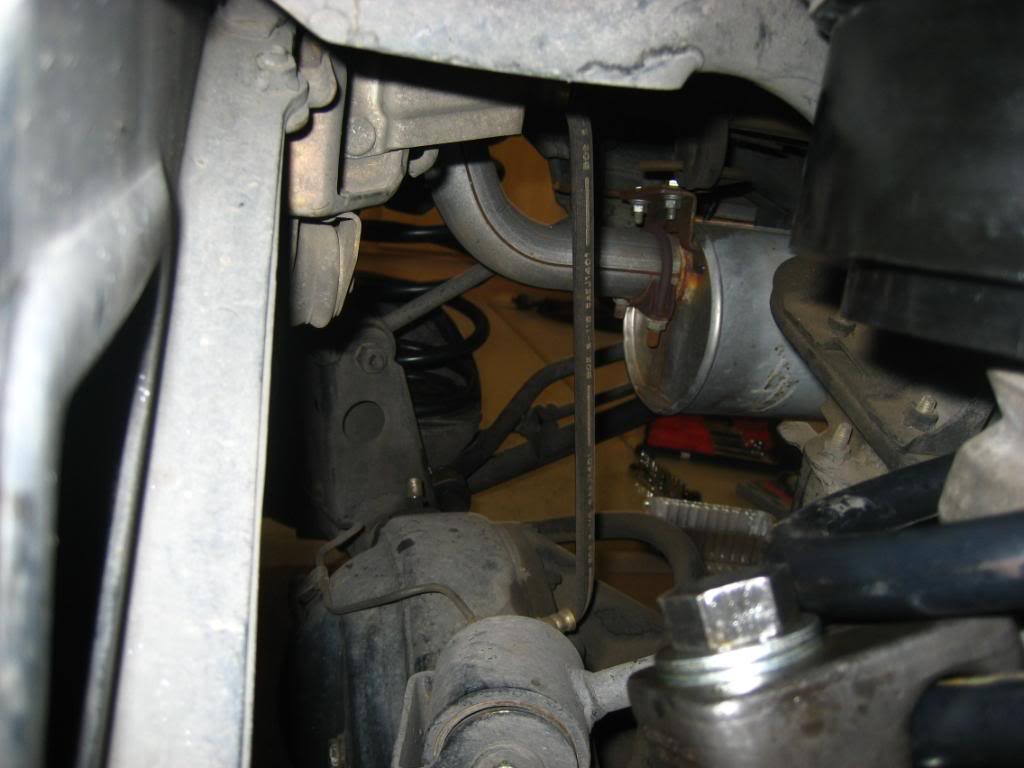
Below is the ordeal with the spring compressor with the stock brake line attached and not having the track bar drop bracket. Before this I removed the rear shocks, removed the sway bar end link nuts and removed the track bar from the axle. I used my floor jack to support the axle under the rear differential:
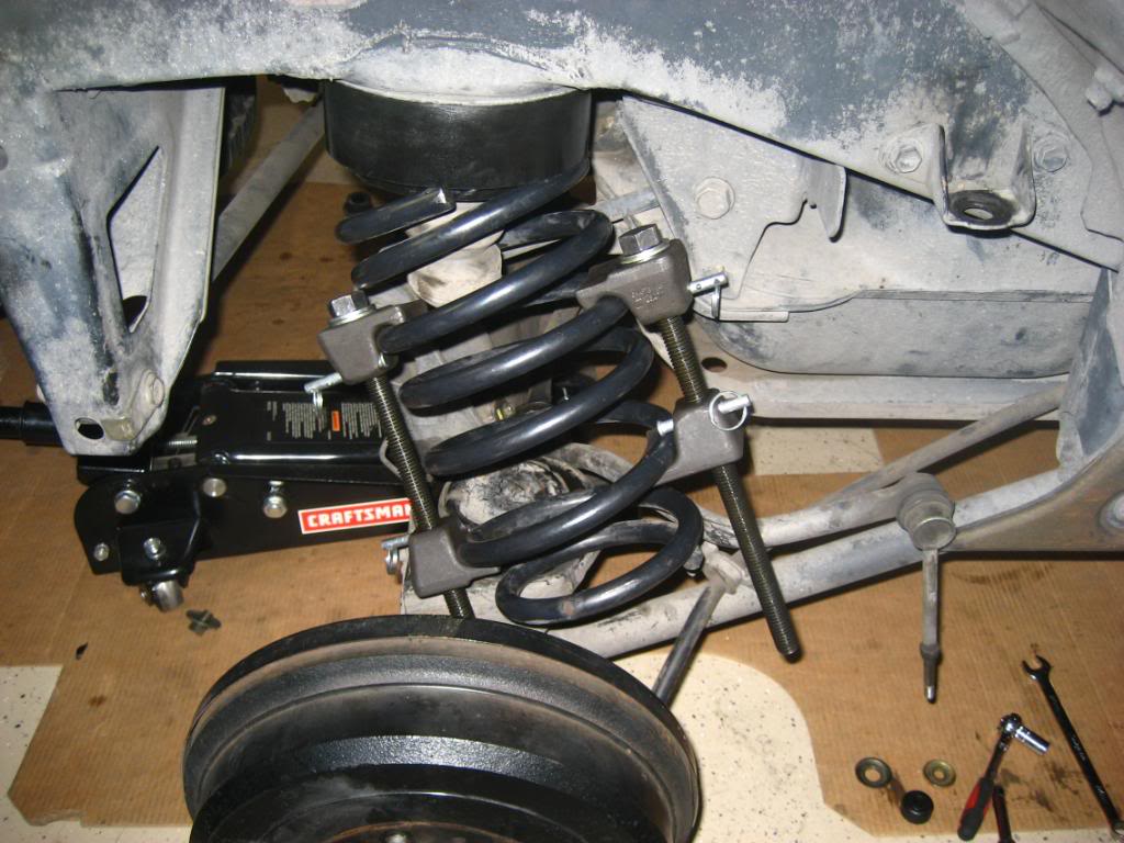
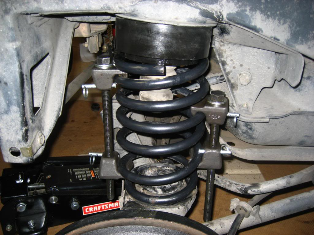
It is possible to do this job with out a longer brake line but it’s a real pain because now you have to mess with a spring compressor much more then you would if you had the longer brake line. There’s not much space to work with on the passenger side due to the track bar bracket on the chassis, this limits the amount of clearance you will have with the coil and a spring compressor attached, all the time trying to contort it onto the spring seats with the polyurethane spacer on the top and the irritating and very tall bump stop in the upper spring seat that sits inside of the rear coil. You can only lower the rear axle so far too with out putting a strain on the shorter stock brake line. In my opinion it’s just not worth doing the install without a longer brake line and also the track bar drop bracket (I’ll explain this more in detail later). Trust me, I experienced it.
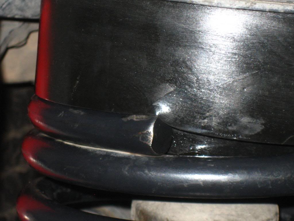
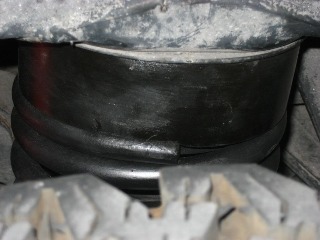
One thing I did not like was the huge indent the rear coils were putting in the spring spacers. A quick email to Rodger and he said that the spacers are pretty resilient because they’re polyurethane and that it wouldn’t hurt them. He also mentioned that if I wanted to I could shave the tops to a flatter edge to reduce the indent that would be made by the spring. This is what I figured he would reply so with that in mind the coils came back out again. I didn’t have an angle grinder at the time but I did have the $7 Harbor Freight special. I also picked up an extra pack of cutting wheels while there just in case, which ended up coming in really handy.
Without shaving the coil:
After shaving with the air cutter in a back and forth motion so the cutting blade made an even grind instead of a cut:
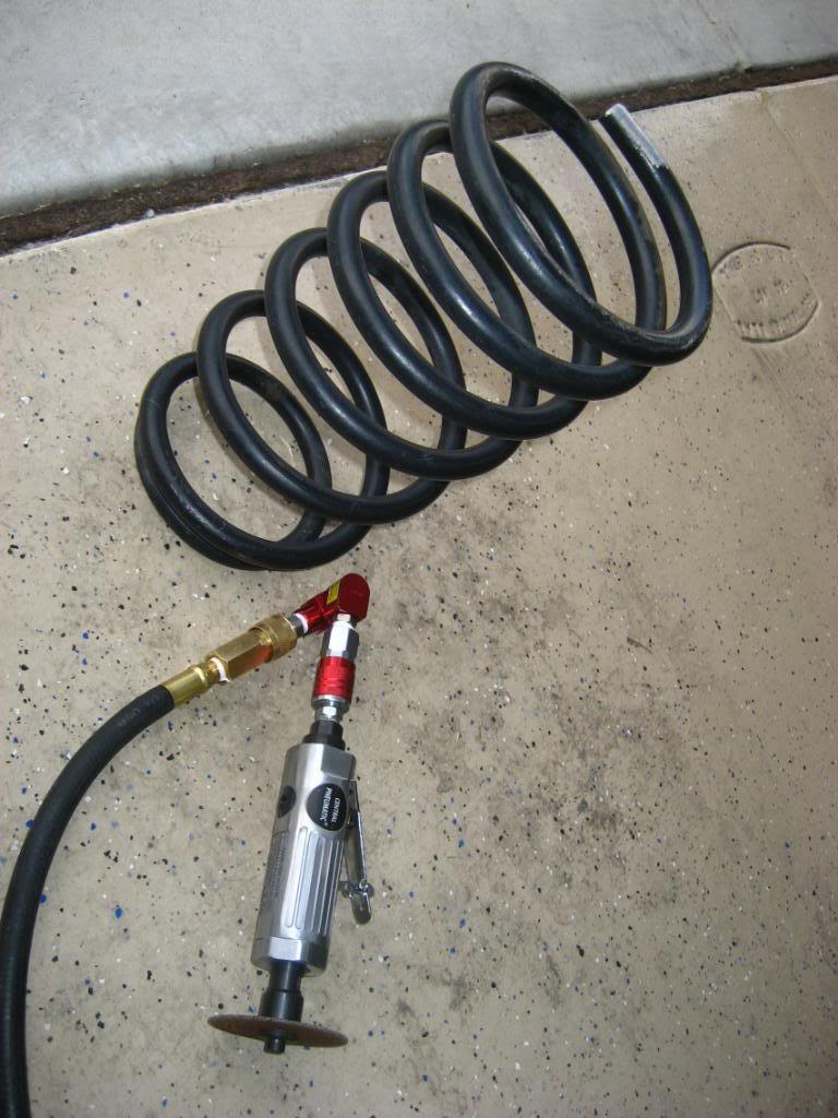
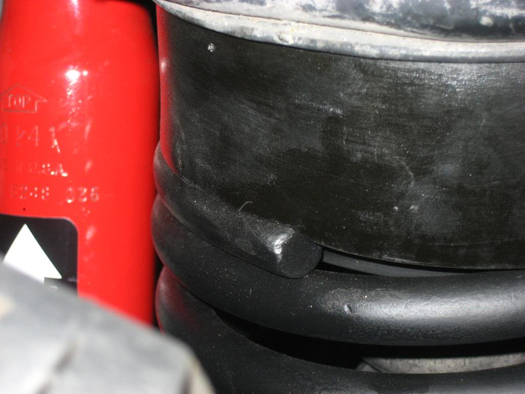
After however long it took with the air cutter I was able to achieve what I had wanted. I then sprayed the coils with primer and flat black; after the paint was cured it was time for the coils to go back on.
So now the spacers and coils are on, again. Time to bolt everything up. Yeah…to bad I couldn’t get the track bar back on. Apparently, at least for my truck the 2” coil spacers were tall enough to change the angle of the rear axle enough to the point where I couldn’t get the track bar back on the axle and due to the 2” spacers the angle of the track bar was even steeper. I needed the axle to pull towards the passenger side so I could put the track bar back on the stud that comes off the axle on the driver’s side. Fast forward to several emails later to Rodger and I still couldn’t get it on. I tried adding extra weight to the rear end with my friend sitting on the tail gate and jacking up the axle up on the passenger side but all of this just wasn’t enough. There was also some debate concerning my springs with other Yotatech’ers and Rodger. My rear coils are only 2+ years old, McQuay Norris from Checker Auto. I got these to replace the stock ones which were sagging.
Rodger mentioned that the springs that I got could be slightly taller and when paired with the coil spacers could be causing my difficulty with the track bar. All I know is that when I installed the springs when I got them my rear end was restored to the proper ride height so I am under the assumption that these springs are not any taller than they should be. However, because of this mess I decided to order the 4” track bar drop bracket that night in hopes that this would do it for me.
Hey guess what, now I get to take everything off again tonight so I can have my truck for work tomorrow.
Note the stock brake line being stretched to its limit:
If you’re wondering why I ordered a 4” track bar drop bracket for a 2” lift then I’ll get into that a little later…
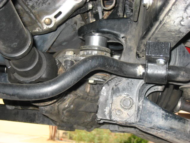
A couple days later the drop bracket deluxe kit is installed (all hardware needed is included with the deluxe kit), painted flat black to match. All spacers and springs back in…
Well still no luck, same problem but NOT as bad as before. The drop bracket helped the angle of the track bar to where I was a few hairs off, but if I can’t get the track bar on it doesn’t matter how far I’m off.
Rodger also mentioned to me in one of his emails that I could use a come-along to help pull the axle closer to the passenger side so I could get the track bar back on. With nothing else working it was time to go back to Harbor Freight thanks to my friend picking me up. $16 later and I was back at home with a 2-ton capacity (At least that’s what they claim…Ohhh look, made in China) come-along/hand winch.
If you’re not familiar with a come-along it’s nothing more then your typical ratcheting tie down strap on roids. You don’t actually use this as a tie down but they both work in the same manner but the come-along is obviously a lot stronger and has a handle that you can use to apply some serious pulling power to the job.
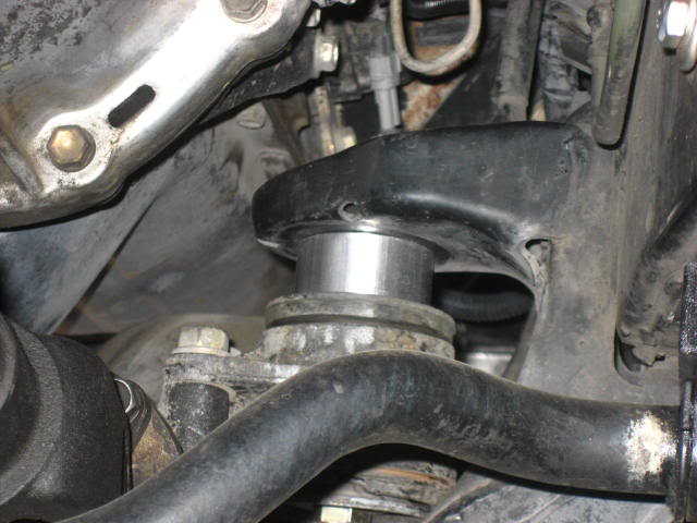
Below shows the end hook of the come-along hooked on the bracket for the track bar, finally I was able to get the track bar on the stud:
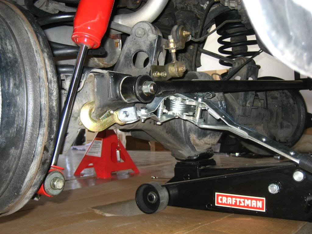
Another view:
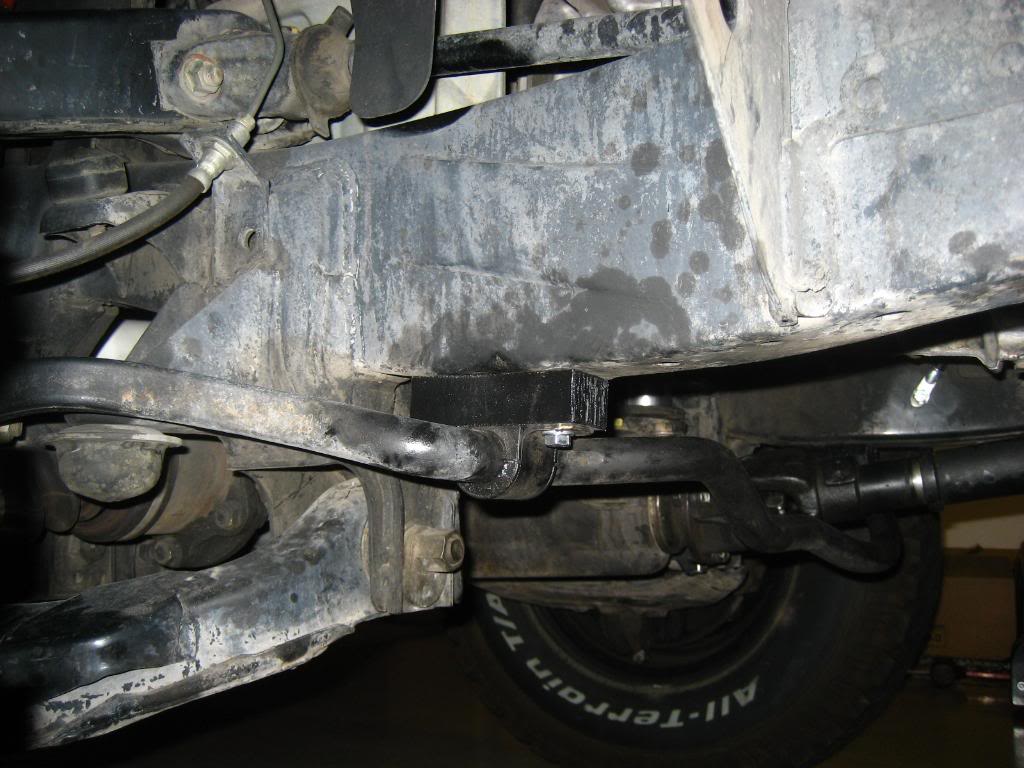
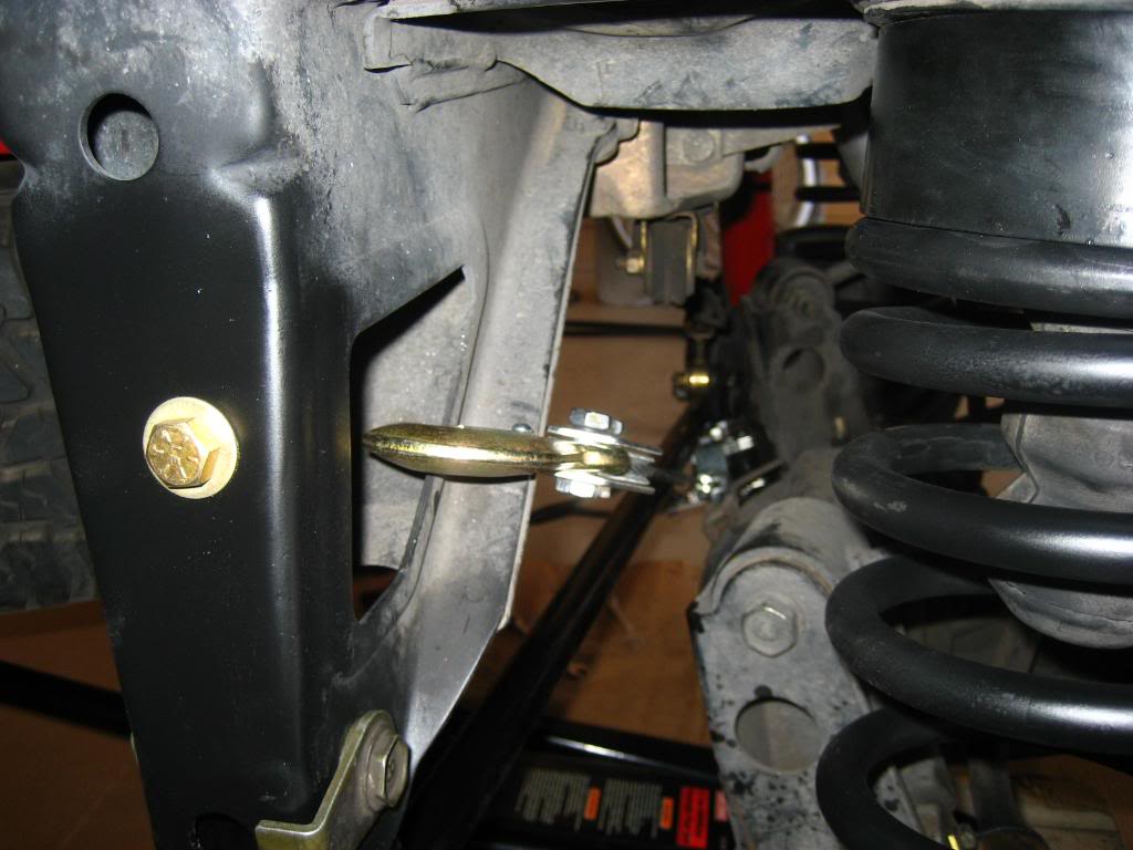
Below is where the other hook went, the track bar bracket; note the shiny golden bolt on the stock track bar bracket, that’s where I had to drill a hole in order to install the deluxe drop bracket kit:

A few cranks later and the track bar was back on and bolted up, I couldn’t believe how east that was. In my opinion, like the air cutter both of these Harbor Freight tools paid for themselves after using them for this job. If I had this come-along/hand winch from the beginning I would have saved myself so much time.
Finally everything was on and I could at least drive my truck now with an even lift on all four corners. Time to order the longer rear brake line and a LSPV (Load Sensing Proportioning Valve) Relocation Bracket.
Here’s the new Energy Suspension black polyurethane bushings on the rear sway bar end links (stock rubber bushings were squashed and had cracks throughout):
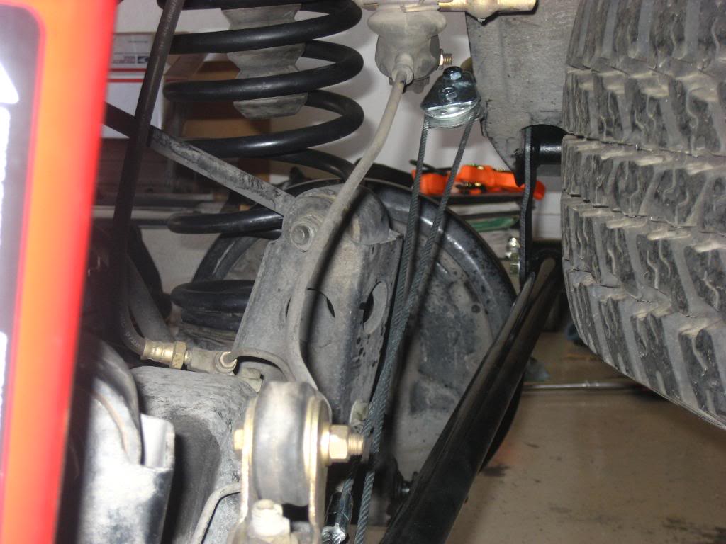
A couple of day’s later and the new Crown brake line is installed (I even got a free Marlin Crawler sticker with my order), brakes bled and the new 4” LSPV relocation bracket is on.
I put some wire loom around the brake line to help protect it from rubbing against the gas tank and the sway bar during rear suspension travel. You will have to get a bigger brake line clip to hold the Crown brake line on the Bracket next to the LSPV, the stock clip used on the OEM brake line is too small. Notice I used a big E-Clip I got from Ace Hardware.
Another view:
Below is the LSPV bracket with an extra set of holes that I drilled myself. The bigger holes at the top were pre-drilled. I drilled out the 4 holes below that; each spaced an inch apart vertically.
The bolts that hold the LSPV bracket to the track bar and the nuts that hold the pivot point link bracket are 2” apart, the same height as the spacers. My goal was to get the angle of the LSPV rod to how it was before the spacers were installed. That way no adjustments would be needed to the LSPV. I had to place 2 nuts in front of the LSPV bracket before bolting down the pivot point link bracket to allow for clearance during rear suspension travel.
Without the nuts acting as spacers the end of the link would scrape against the LSPV bracket (near the top right hole in the LSPV bracket).
If this truck ever get’s higher in the future I have 2 extra inches on this bracket to play with. After installing the LSPV bracket I did not notice any performance changes in the rear braking so I felt that there was nothing to adjust for on the LSPV itself. If felt as normal as it did before the lift.
Getting back to the 4” track bar drop bracket for a 2” rear coil lift, the custom size brackets are more expensive and take longer to ship as they are fabricated when ordered. Rodger usually always keeps a stock pile of the 4” brackets in stock. Besides me being cheap there’s a more important reason for me getting the 4” drop bracket. With all my emails to Rodger concerning my track bar (Panhard rod) issues he sent me this article on how the track bar angle should be on any vehicle…
http://www.popularhotrodding.com/tec...ide/index.html
As mentioned in the 13th paragraph of the article:
"The Panhard rod should be as long as possible and be mounted horizontal to the axle at static ride height. An angled Panhard rod will cause the axle to move sideways during suspension travel."
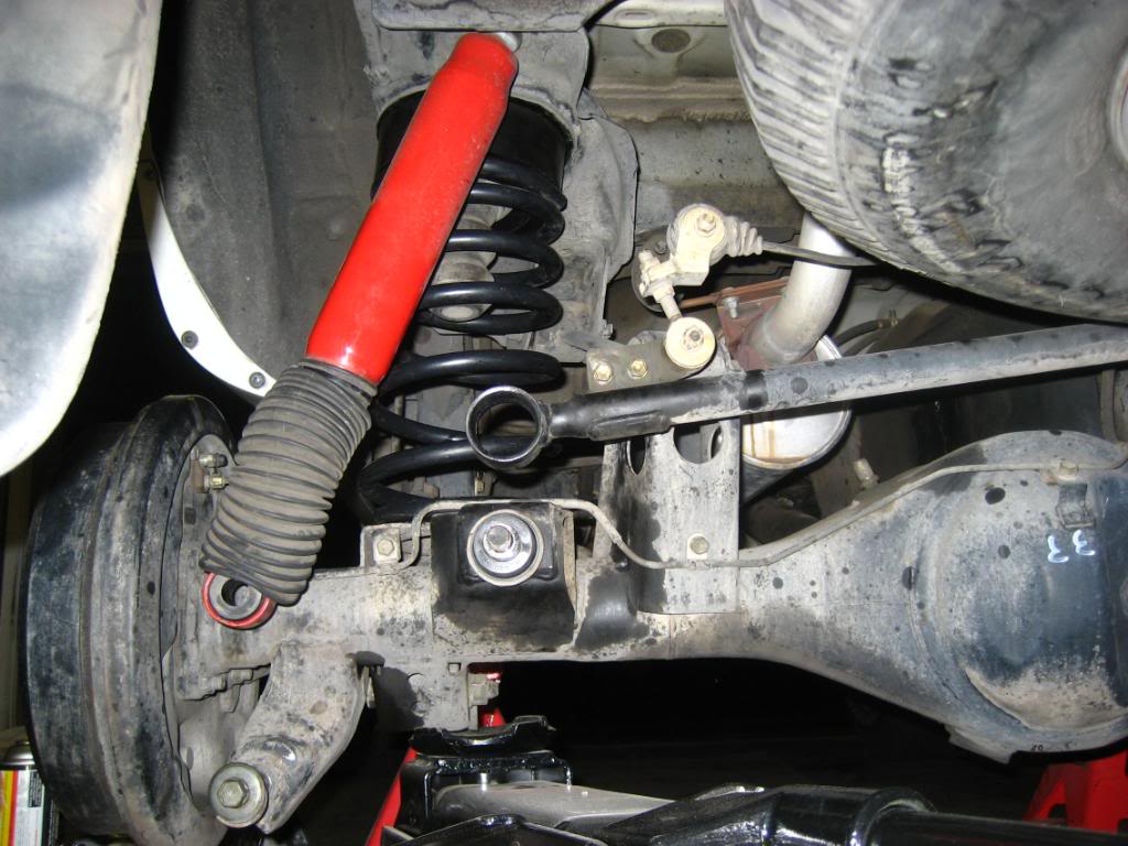
With this in mind and making the appropriate measurements as described on 4Crawler.com the logical choice for my truck was the 4” drop bracket. It’s also funny because of all my emails and troubles I permanently scared 4Crawlers website. He posted this article link along with a picture the next day as to how the track bar should look on the back of a 4Runner.
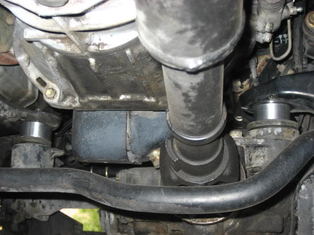
And here’s how mine came out in the end:
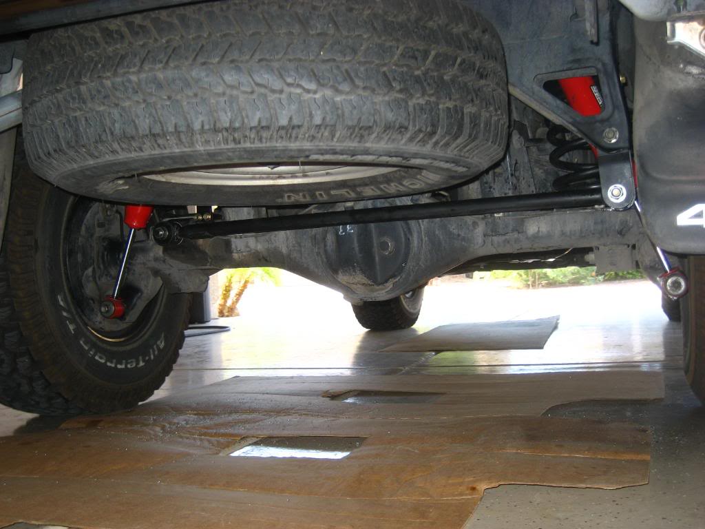
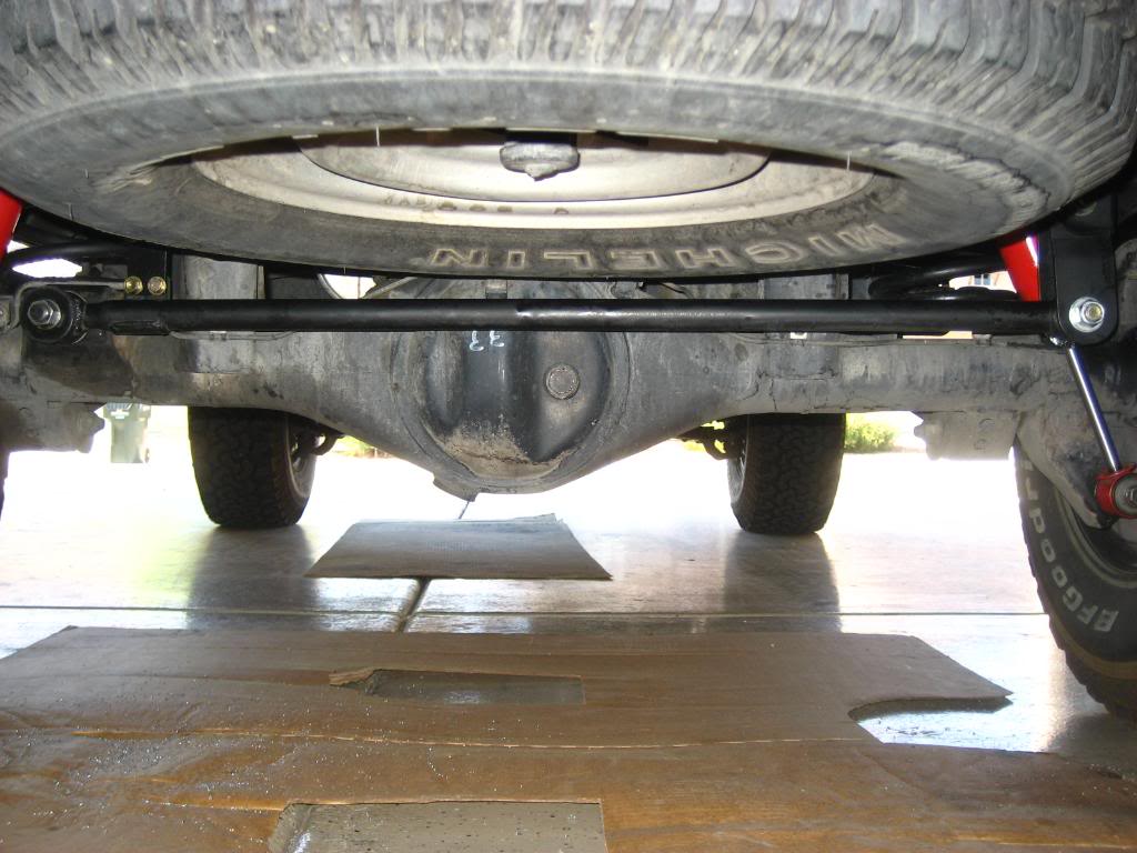
Notice above that my track bar is about as horizontal as it can get. The distance from the ground to the center of the track bar stud on the driver’s side compared to the distance from the ground to the center of the mounting bolt on the passenger side is within half of an inch of each other. This proves that just because you may have a 2” lift in the rear doesn’t mean that you automatically need a 2” drop bracket. Read on 4Crawler on how to correctly measure for your truck before you order!!
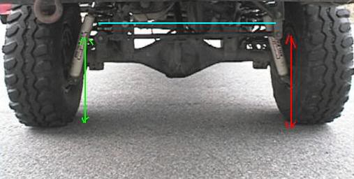
Below is the example that Rodger posted on 4Crawler.com because of all my troubles; the track bar is almost horizontal with the axle:
The scarring didn’t end there. Rodger would again be adding to his page. I had a few emails back and forth again with him concerning a banging noise form the rear end during moderate to heavy braking and moderate to heavy acceleration from a dead stop.
Under “check all fasteners in 100-200 miles to make sure they have not loosened” you’ll notice the sentence talking about the “clunking” noise. Well that’s what I had going on. By total coincidence my factory bottle jack somehow got loose in its mounts and started banging around while I was driving right after I completed everything on the rear end.
At first I couldn’t figure out what was going on and after multiple trips underneath the rear end and checking everything to make sure it’s tight I finally remembered that the factory bottle jack is directly behind me under the rear passenger seat, which is in the area where the noise was coming from. Sure enough it was the cause of the problem. I’ve never used that stupid thing anyway because I carry a mini floor jack with me at all times. It went on eBay the next day.
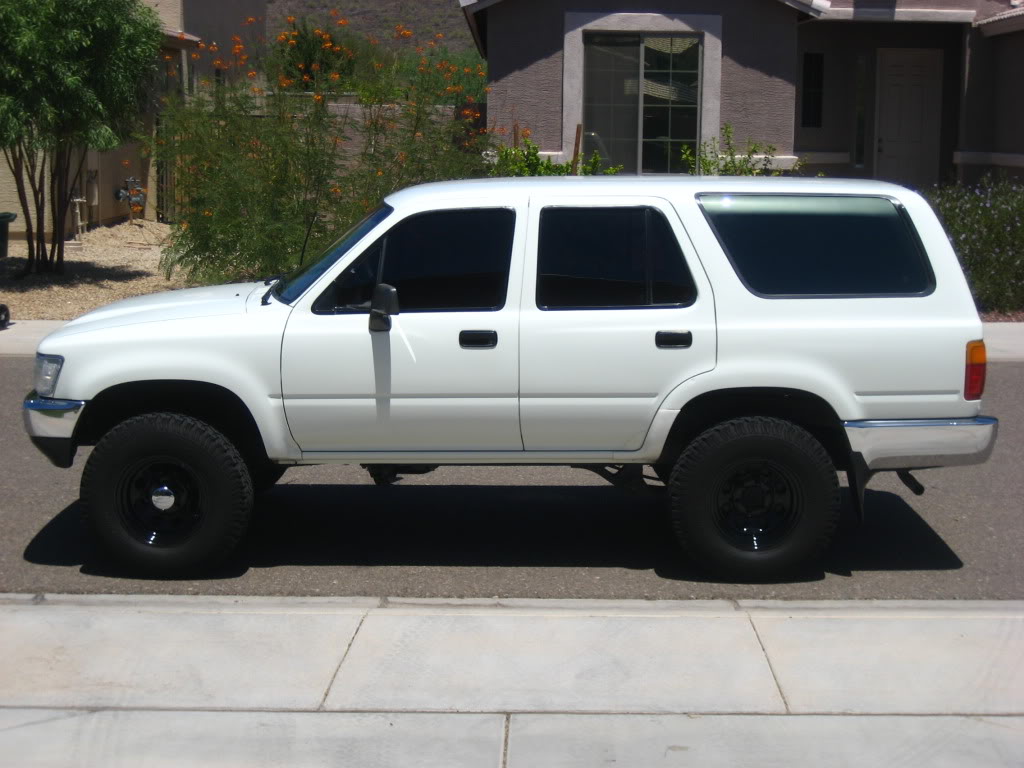
Above is before, below is after:
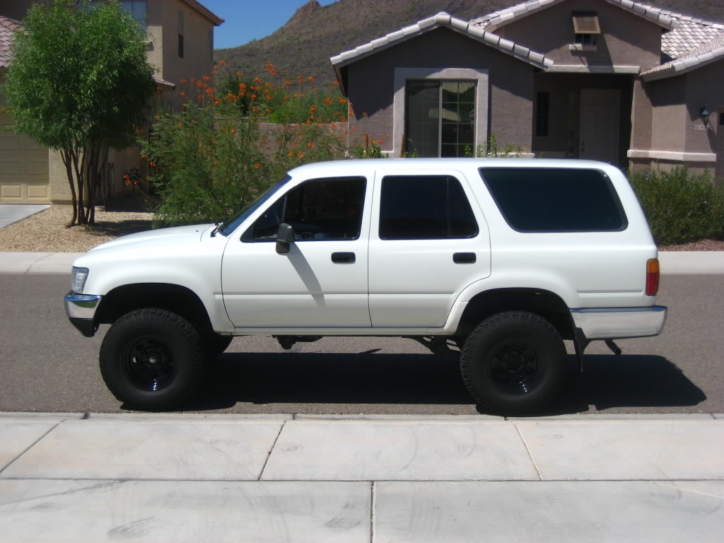
The 2” in lift is really mild however I could immediately tell that I was riding higher when I got in for the first time. It’s really visible by comparing the amount of space between the fenders and the tires when looking at the before and after shots.
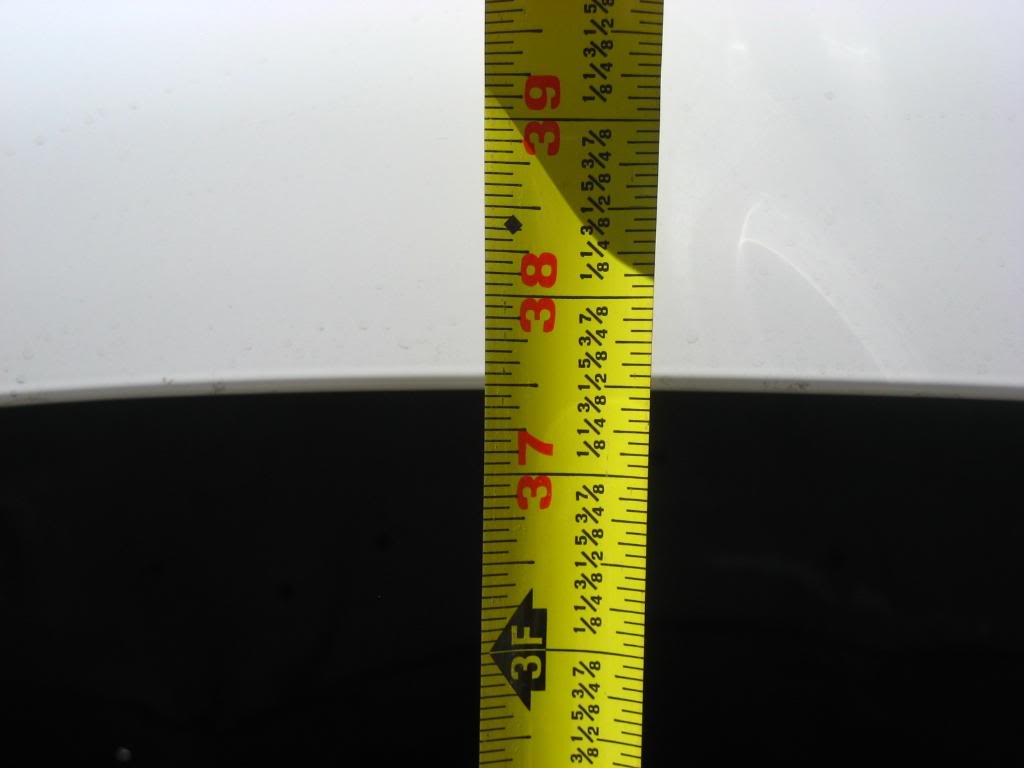
Before the lift - Above is the measurement from the ground to the center of the front drivers side fender, below is the measurement from the ground to the center of the rear drivers side fender. 35.75” up front, 35” in the rear:
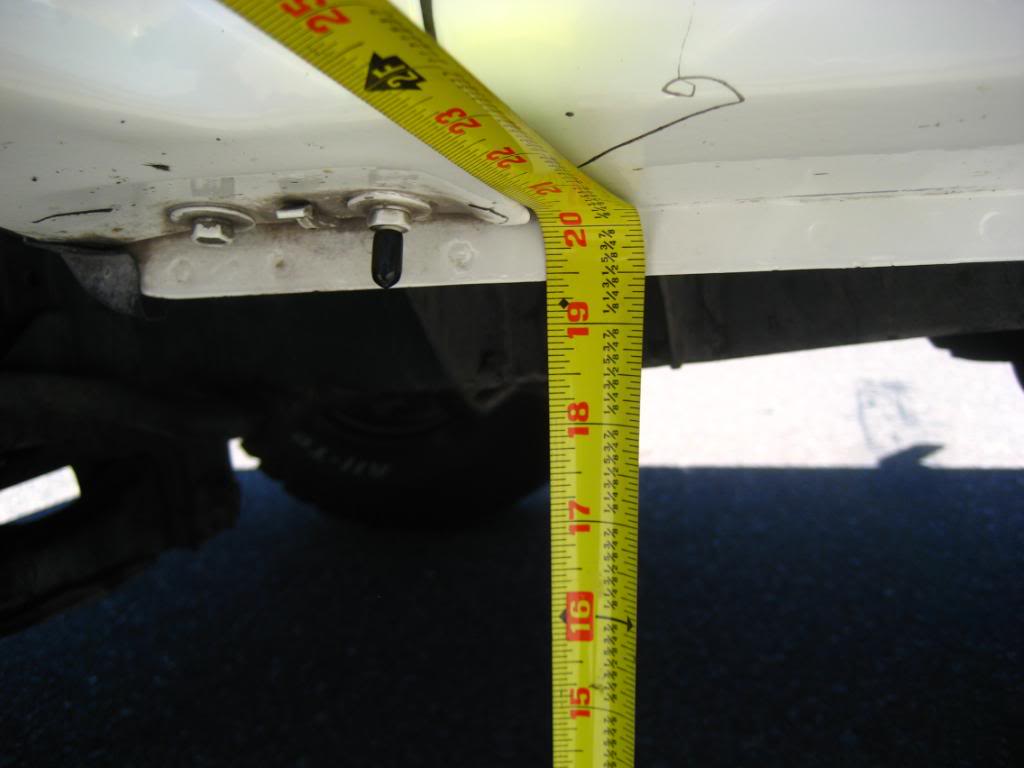
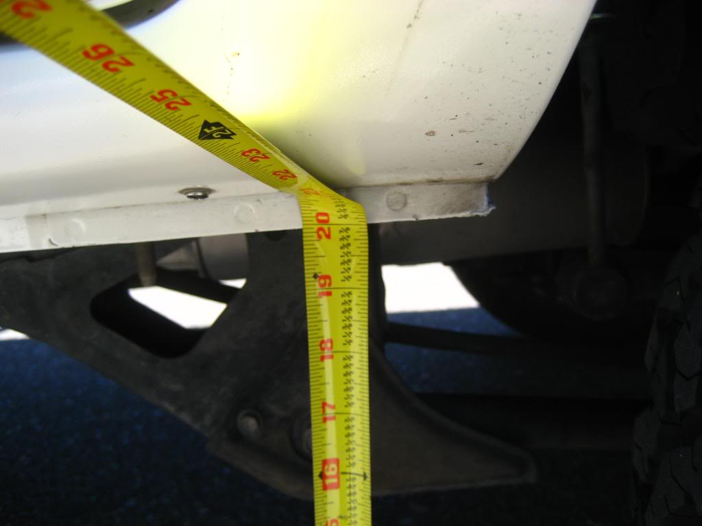
Before the lift - Above is measurement from ground to front driver’s side rocker panel, below is measurement from ground to rear driver’s side rocker panel. 19.5” up front, 20” in the rear:
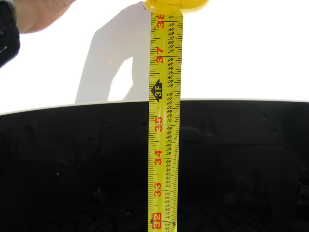
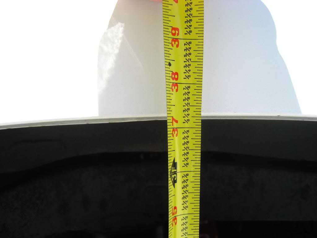
After the lift - Above is the measurement from the ground to the center of the front drivers side fender, below is the measurement from the ground to the center of the rear drivers side fender. 37.5” up front 37.25” in the rear:

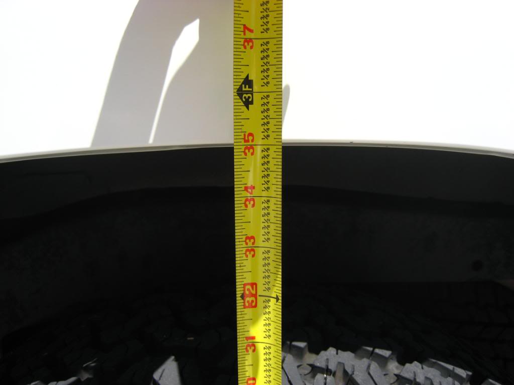
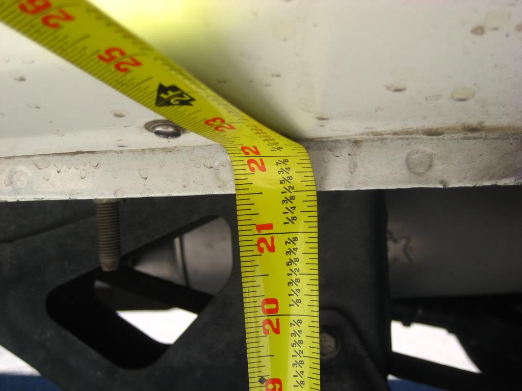
After the lift - Above is measurement from ground to front driver’s side rocker panel, below is measurement from ground to rear driver’s side rocker panel. 21” up front, 21.5” in the rear:
The truck looks level and it looks lifted evenly on all four corners. I also did not have to crank on the torsion bars since it lifted evenly but more importantly it sits evenly. I had thoughts about getting after market torsion bars, like a pair of Sway-A-Way’s but I was told that unless I have more weight up front (bumper, winch, engine swap, etc) the stock torsion bars will work just fine, especially since I mostly drive on the pavement. There’s no doubt that after 18 years the stock torsion bars are fatigued but they’re still working fine.
When I removed my shocks before the install I took the boots off of them, put the shocks back on and then made sharpie pen marks on the shafts out of curiosity to see what it would look like before and after.
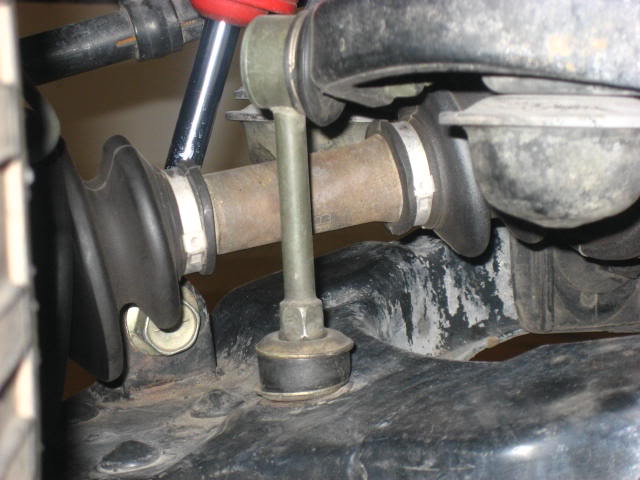
Below shows my front shock shaft that I marked with a sharpie before installing the BJ spacers. Although I did not take measurement it looks like an extra inch of travel has been added. Judging by the space between the bump stop and lower control arm it looks like I have more than an inch if not the full 1.5” of new travel now. I plan to add some low profile bump stops from Energy Suspension soon, this way I can get a little more travel out of the front end:
The rear shock shafts became extended by 2” and my shocks still provided enough travel for the lift.
I actually installed this lift a few months ago and decided to use the test of time before I did a write up on my thoughts and experiences. Overall I think the truck looks better and it actually rides better too. The extra suspension travel has really made a noticeable difference. Hitting bumps in the road before that would cause the truck to really react or bottom out are handled a lot more smoothly now. The truck doesn’t bottom out as much as it once did. One example is driving over a section of cobble stone. My shocks might be working harder but I’m feeling less of it in the cab now. It also helps to have a good set of shocks on all four corners to keep the springs under control.
The last thing to do is to GET AN ALIGNMENT. By adding the BJ spacers all of the alignment angles on the front end are off…way off. Get this done right away to help save your tires and for safety when you’re driving down the road.
Also…Do not forget to check all fasteners as noted on 4Crawler under “check all fasteners in 100-200 miles to make sure they have not loosened”. I checked mine well over 200 miles and I had some hex bolts on both BJ spacers requiring a re-torque of 25ft. Ibs.
In the couple of months that I have been driving the truck I haven’t had any problems. Overall I have been really happy with the results from this project.
Special thanks to all who replied to my thread posts on Yotatech for help and especially to Rodger Brown from 4Crawler.com and Wabfab for the powder coating.
Below is the links that I posted during the install when I needed some extra advice…
https://www.yotatech.com/forums/f116...erence-189310/
https://www.yotatech.com/forums/f116...roblem-188670/
https://www.yotatech.com/forums/f116...ck-bar-186753/
Don’t know how to install spacers? Hopefully this helps.
The truck:
91’ 22RE 5spd 4WD SR5 4Runner
Stuff Installed:
1.5” SDORI/4Crawler BJ (Ball Joint) Spacers, IFS Diff Drop Deluxe Kit, Energy Suspension’s Black Polyurethane Sway Bar Bushing kit (Front Part # 8.5114G), (Rear Part # 8.5115G), MOOG ball joints. 4Crawler 2” Rear Coil Spring Spacers, 4Crawler 4” LSPV (Load Sensing Proportioning Valve) Relocation Bracket, 4Crawler 4” Track Bar (Pan Hard Rod) Deluxe Drop Bracket kit. Crown 26” clear Male-Female Rear Brake Line from Marlin Crawler. Aisin Manual Locking Hubs (86’-95’).
Depending on the shocks that you have you may or may not need longer shocks after the install of the spacers.
I’ll start with the front end first…
Tools needed: Some type of cutter or grinder to cut the upper control arms, metric sockets (shallow and deep), ratchets, various socket extensions, torque wrench (I used a 3/8” and ˝”), metric hex bit socket (6mm), open end/box wrenches, hammer, pry bar, penetrating lubricant, patience, beverages of choice.
Optional: Air Compressor, air tools, impact sockets, sharpie pen, tape-measure, ruler, spray paints, sand paper of various grits, #00 steel wool.
BJ Spacer’s:
The BJ Spacers are just blocks of milled aluminum that fit in-between the upper ball joint and upper control arm, hence the name. Once installed the upper control arm retains its original angle because it has the tension of the torsion bar always pushing down on it, just as it always had. Because of this any spacer mounted in between the upper ball joint and upper control arm will lift the front end of the truck as tall as the spacer is (usually, give or take a few…). This happens because you effectively push the lower control arm down as much as the spacer is tall, which in turn drops the original placement of the hub/knuckle/spindle shaft (further south of the fender) which allows the truck to sit higher.
I chose to use the 1.5” BJ Spacers that Rodger Brown from 4Crawler.com sells. Rodger actually sells the spacers made by SDORI (San Diego Off-Road Innovations). Paired along with 2” polyurethane Rear Coil Spring Spacers (also from 4Crawler) I thought that this would be a good but mild lift for my 4Runner, giving me a total of 2” of lift overall.
After receiving them in the mail I opted to add an extra layer of protection to them with a coat of RUST-OLEUM Gloss Clear Coat. This came after a light rub down with #00 steel wool, which also really polished them up. After a few sprays of brake cleaner to clean them off I gave them two coats each of the clear. Although this isn’t the absolute proper way to prep and apply paint to an aluminum surface they have looked shiny ever since instead of turning to the dull oxidized aluminum look. After the clear coat was cured it was time to install these milled paper weights.
Refer to Rodger’s install page for help and tips,
http://www.4crawler.com/4x4/ForSale/...er_HowTo.shtml
After jacking the truck up and placing it on jack stands I first started by using PB Blaster on every fastener that I knew I was going to remove. Let it soak for a few minutes. Then I proceeded to remove the front shock. One thing to consider is that you might want to change your ball joints out if needed at this time since you have everything apart for this job anyway.
I bought a set of MOOG ball joints. At least for my 91’ 4Runner, these are the MOOG part numbers.
(Upper Ball Joint # K9482, Lower Ball Joint # K9519).
Passenger and driver side will use the same ball joints, so two of each.
((Upper ball joint to upper control arm, 13mm socket (6mm Hex bit socket if you install the BJ spacers with the included hardware), torque to 25 ft. Ibs. 27mm socket for stud to steering knuckle, torque to 105 ft. Ibs. Included Zirk fitting, 8mm socket, hand tighten snug. --- Lower ball joint to steering knuckle, 17mm socket torque to 43 ft. Ibs. 27mm socket for stud to lower control arm, torque to 105 ft. Ibs. Included Zirk fitting, 3/8” open end wrench, hand tighten snug.))
I first removed the sway bar link nuts at the lower control arm (14mm deep socket) on both sides so the lower arms would drop down far enough for the install.
Before removing the upper ball joint from the upper control arm I placed a Snap-On 3/8 drive 17mm impact socket between the upper control arm and upper bump-stop mount. You can do this by jacking up the lower control arm until you have enough space present between the upper control arm and upper bump stop mount. After that simply release the jack and the upper control arm will be pushing down/resting on the socket.
Why you ask? As described on Rodgers page it is helpful to use a type of “wedge” to have the upper control arm sit higher then stock so you will have room to get under and make the appropriate cut in the arm so the BJ spacer will fit.
I used a socket because I didn’t really have anything else lying around in my garage that I could have used. I chose to use an impact socket as they are stronger than standard chrome sockets.
Below is a closer look at the socket that I used to help the upper control arm sit higher.
I then removed the ball joint from the arm. Although you can’t see it pictured below I left my floor jack under the lower arm to help support the weight of everything before I actually removed the bolts and nuts. Once all the bolts were off I slowly lowered the jack to separate the ball joint from the upper arm.
Do not let the arm lower itself as low as it would want to go; leaving the jack under the lower control arm will help the CV axle from separating at the joints/boots. If this happens, as it did to me you will have to gently turn the brake rotor/axle back and forth while pushing inward until the CV joint set’s back in place. You can tell because the CV boot will look like how it’s supposed to instead of stretched out and kinked.
Because I already had a 30 gallon Craftsman Compressor I chose to use a high speed air cutter to do my cutting of the upper control arm. I went to the highest quality tool store available in all the land…Harbor Freight. Best $7 I ever spent and amazingly the air cutter still works after this job was completed! Sure put my compressor to work; this thing uses a lot of air.
Don’t forget to wear safety glasses when cutting because the sparks will be flying. I also picked up a pair of ear muffs at Harbor Freight. Spending an extra $5 saved me from going deaf from the cutter and the compressor.
This picture above shows how much material I removed from the arm as depicted by the red border. As Rodger says on his install page, only remove as much as you need. This cut took me a couple of try’s to finish as I kept doing a fit check with the BJ spacer but I certainly did not want to butcher my upper arm either. It’s also a good idea to mark the areas you want to cut with a sharpie pen after making measurements.
The shape of the cut is the way it is because of the shape of the BJ spacer and having enough clearance to get it inside the upper arm. Be patient and things will work better in the end. Now you can do it all over again on the opposite side upper control arm.
A couple swipes with the cutting wheel and some sand paper to knock off the rough edges and then a couple sprays of primer & flat black Rust-oleum. I highly recommend this to prevent corrosion later on.
Now it’s time to install the BJ spacers. This is an easy task as you will just use the new hardware provided in the kit. This consists of longer hex bolts which will require a 6mm hex bit socket, a set of lock nuts and regular nuts and washers. It took some juggling to get the spacer seated properly, I had to tug on the lower control arm at the same time trying to rest the BJ spacer on the ball joint and then getting everything under the lip of the arm.
Don’t forget to mount the spacers with the weep holes/notches facing down! This is a drain to let any water out instead of sitting on top of the ball joint. If the water can’t drain then corrosion will occur.
Once in the arm simply bolt down. This is where I used a 3/8” drive 6mm hex bit socket on my 3/8” drive torque wrench. Torque regular nut (1/2”) and hex bolt to 25ft Ibs. Then snug the nylon lock nut (13mm) down on top of the regular nut. This will prevent the regular nut from backing off and coming loose in the future.
The next group of pictures below shows what it should look like after installed
Below is a view from behind the front passenger tire looking up to the BJ spacer:
Below is a view from the front of the truck looking up to the passenger side BJ Spacer:
After the BJ spacers are installed you can put the front shock back on. This was also a good time for me to install the IFS Diff Drop Deluxe Kit, which includes 4Crawler’s 1” front sway bar drop kit and 1” front differential drop kit.
The sway bar drop kit that Rodger sells is nothing more than 1” spacers and it helps the sway bar retain its original angle and height in relation to the lower control arm after sitting lower now from the lift. Each spacer looks like milled Delrin to me. I chose to paint my spacers flat black to help blend in with the chassis.
Below is the front sway bar drop spacers and Energy Suspension polyurethane sway bar bushings:
After the paint cured I simply unbolted the stock sway bar mounts on the chassis and put the spacers in place. Since I had removed the sway bar mounts I also installed Energy Suspension’s Black Polyurethane Sway Bar Bushing kit (Part # 8.5114G). This kit includes 2 bushings for the sway bar and all the bushings and washers needed for the end links. It also includes a tube of Energy Suspensions Formula 5 grease for polyurethane bushings. The old stock rubber bushings were well past their life span. Visible cracks and chips in the rubber were present. I then bolted everything back up with the new and longer hardware provided.
Below is the new Energy Suspension polyurethane sway bar end link bushings:
I then attempted to install the 1” front differential drop kit to help alleviate the CV angles from becoming to steep due to the lift from the BJ spacers. You can find more information about this on 4Crawlers website.
Just like the BJ spacers this kit is also milled aluminum and just like what I did to the BJ spacers I did the same to theses. A couple swipes of steel wool and some clear coat. They shined up really well.
I then loosened the bolt on the front of the differential and then removed the 2 bolts, washers and nuts in the rear of the differential, all the time having my floor jack supporting the weight of the differential in the back near the driveshaft.
Once I lowered the differential with the jack I was able to slide the spacers in place but I ended up having a very difficult time getting the included longer bolt to go into the spacer on the passenger side. I just couldn’t get the differential and spacer to line up so the bolt could go through both of then and the hole in the chassis. I figured this was due to the fact that the spacer is as tall as it is and because the front of the differential is bolted closer to the passenger side instead of in the middle of the truck. This made pivoting the differential in the direction needed a lot more difficult compared to the drivers side. I had to use a pry bar on the front differential in order to line the holes up while trying to install the bolt with my other hand. This was not easy or fun.
As of now there is a lot of tension on that bolt. I could loosen the drivers side and it would probably fall out of the hole on it’s own but it won’t happen for the bolt on the passenger side. I tried searching for any problems like this that others may have encountered but I couldn’t find anything on this subject. It’s in now and seems to be working fine.
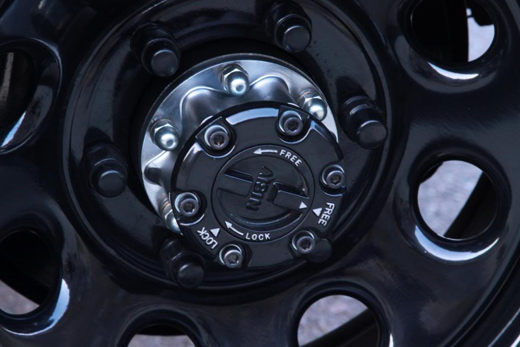
To further help the CV’s out I got my hands on a pair of Aisin Seiki Manual Locking Hubs off of eBay (if you’re not in a rush I suggest you roam the local junkyards as you can probably get them a lot cheaper).
Now my CV’s won’t be constantly spinning as I’m driving in 2wd. This helps to extend the life of the boot’s and CV joints. As far as I know these hubs will fit 4Runners from 86’- 95’. Before installing the hubs I shipped my free wheeling hub covers and control handles to Wabfab for powder coating and new gaskets. They did a great job and it looks brand new again. I did however have to remove some of the powder coating on the free wheeling hub cover tabs and control handle edges because the powder coating was too thick. Once removed I was able to install the handles into the covers.
There’s a lot of info on these hubs online. If you’re not familiar with these hubs and how they go together then here’s a few links below that I had to use to help me put them back together. Just take your time and it will work out. I had no knowledge of these hubs until they showed up on my doorstep and I started to tear them down. I also had to get a pair of internal/external ring pliers in order to work on these hubs. Got a pair of large Craftsman Professional from Sears with interchangeable tips, about $30.
http://www.off-road.com/trucks4x4/ar....jsp?id=399612
http://www.off-road.com/offroad/arti....jsp?id=399668
http://forum.ih8mud.com/79-95-toyota...b-rebuild.html
http://www.4x4wire.com/toyota/mainte...d/hub_rebuild/
Here’s the Toyota factory manual excerpt for the Aisin manual hubs in PDF format so you can download them to your computer. This is handy to have when you’re messing with them.
http://www.yankeetoys.org/Documents/AisinHubs.pdf
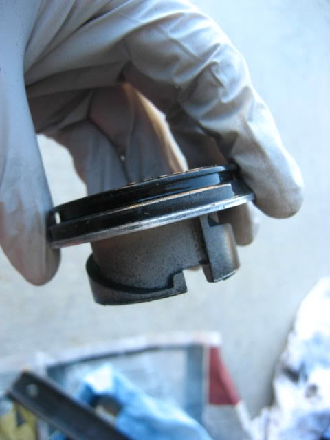
Above are the covers when they arrived to me from Wabfab. Below shows the tabs after they were lightly sanded using my Dremel. You can do these by hand with some sandpaper but it would take a lot longer.
Below is the handle, the powder coating on the outer edge was a little to thick.
After lightly sanding with my Dremel.
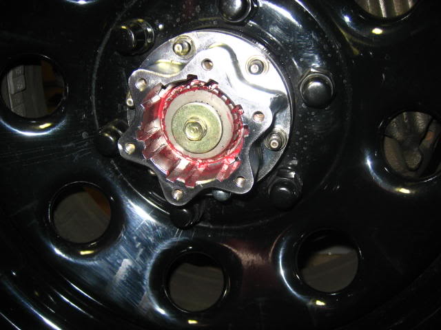
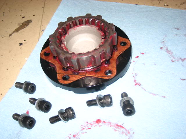
Hub body completely cleaned, re-greased and ready to be bolted on the hub with new hub gasket. Torque hub fasteners to 23 ft. Ibs.
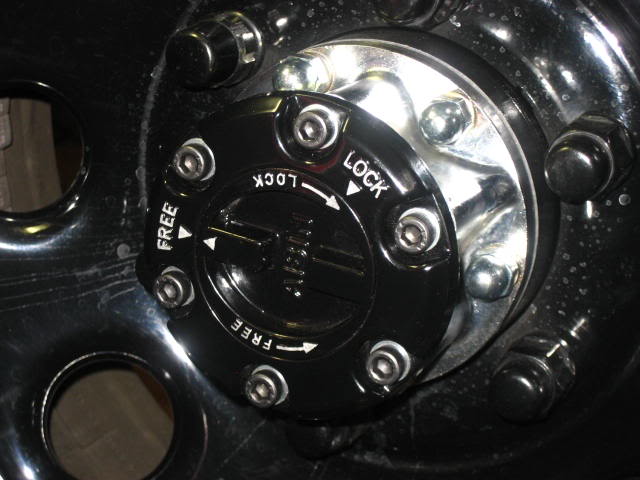
Cover, handle and new star gasket ready to go on. Torque cover fasteners to 7 ft. Ibs.
Now the CV’s can rest. I also chose to use different hardware then the standard and stock 10mm socket size nuts and hex bolts.
This completed all the front end mods.
Rear Suspension…
I actually did the rear suspension first because I knew I couldn’t finish everything in 1 day and I use my truck everyday. I figured I would go with the jacked up hot rod look for a couple of days instead of an over exaggerated sagging rear end look by doing the BJ spacers first. The rear end actually took much longer then it should of. I didn’t order all the parts I needed at the same time, etc, etc…
Tools needed: Grinder to shave the tops of your coils (optional), metric sockets, ratchets, various socket extensions, torque wrench, breaker bar, ˝” impact gun (optional), spring compressor (optional), open end/box wrenches, flare nut wrenches for the brake line, drill for the 4” track bar drop bracket, ball peen hammer, dead blow hammer, come-along/hand winch, pry bar, penetrating lubricant and more patience.
First things first, don’t do what I did. Have all the tools that you need (get your hands on a come along/hand winch) and get yourself a longer rear brake line and the track bar drop bracket, also you might want to consider an LSPV relocation bracket as I ended up needing one. Spending $29 for the brake line before you begin the project will make the job more enjoyable and if you haven’t bled your brakes in awhile then you’ll hit 2 birds with one stone. Brake fluid does wear out.
I ordered my Male-Female rear brake line from Marlin Crawler. It’s made by Crown, supposed to be really good stuff and its 26” long, more then enough length for a coil spring spacer lift. There’s also 3 colors’ to choose from, blue red and clear. I went with the clear. The same goes for the track bar drop bracket and LSPV bracket, at least for me and my truck not having it when I needed it made things a lot more difficult. I was under the impression that because I was only lifting the truck 2” I would not need them. This turned out to be untrue. Very untrue.
Below is the ordeal with the spring compressor with the stock brake line attached and not having the track bar drop bracket. Before this I removed the rear shocks, removed the sway bar end link nuts and removed the track bar from the axle. I used my floor jack to support the axle under the rear differential:
It is possible to do this job with out a longer brake line but it’s a real pain because now you have to mess with a spring compressor much more then you would if you had the longer brake line. There’s not much space to work with on the passenger side due to the track bar bracket on the chassis, this limits the amount of clearance you will have with the coil and a spring compressor attached, all the time trying to contort it onto the spring seats with the polyurethane spacer on the top and the irritating and very tall bump stop in the upper spring seat that sits inside of the rear coil. You can only lower the rear axle so far too with out putting a strain on the shorter stock brake line. In my opinion it’s just not worth doing the install without a longer brake line and also the track bar drop bracket (I’ll explain this more in detail later). Trust me, I experienced it.
One thing I did not like was the huge indent the rear coils were putting in the spring spacers. A quick email to Rodger and he said that the spacers are pretty resilient because they’re polyurethane and that it wouldn’t hurt them. He also mentioned that if I wanted to I could shave the tops to a flatter edge to reduce the indent that would be made by the spring. This is what I figured he would reply so with that in mind the coils came back out again. I didn’t have an angle grinder at the time but I did have the $7 Harbor Freight special. I also picked up an extra pack of cutting wheels while there just in case, which ended up coming in really handy.
Without shaving the coil:
After shaving with the air cutter in a back and forth motion so the cutting blade made an even grind instead of a cut:
After however long it took with the air cutter I was able to achieve what I had wanted. I then sprayed the coils with primer and flat black; after the paint was cured it was time for the coils to go back on.
So now the spacers and coils are on, again. Time to bolt everything up. Yeah…to bad I couldn’t get the track bar back on. Apparently, at least for my truck the 2” coil spacers were tall enough to change the angle of the rear axle enough to the point where I couldn’t get the track bar back on the axle and due to the 2” spacers the angle of the track bar was even steeper. I needed the axle to pull towards the passenger side so I could put the track bar back on the stud that comes off the axle on the driver’s side. Fast forward to several emails later to Rodger and I still couldn’t get it on. I tried adding extra weight to the rear end with my friend sitting on the tail gate and jacking up the axle up on the passenger side but all of this just wasn’t enough. There was also some debate concerning my springs with other Yotatech’ers and Rodger. My rear coils are only 2+ years old, McQuay Norris from Checker Auto. I got these to replace the stock ones which were sagging.
Rodger mentioned that the springs that I got could be slightly taller and when paired with the coil spacers could be causing my difficulty with the track bar. All I know is that when I installed the springs when I got them my rear end was restored to the proper ride height so I am under the assumption that these springs are not any taller than they should be. However, because of this mess I decided to order the 4” track bar drop bracket that night in hopes that this would do it for me.
Hey guess what, now I get to take everything off again tonight so I can have my truck for work tomorrow.
Note the stock brake line being stretched to its limit:
If you’re wondering why I ordered a 4” track bar drop bracket for a 2” lift then I’ll get into that a little later…
A couple days later the drop bracket deluxe kit is installed (all hardware needed is included with the deluxe kit), painted flat black to match. All spacers and springs back in…
Well still no luck, same problem but NOT as bad as before. The drop bracket helped the angle of the track bar to where I was a few hairs off, but if I can’t get the track bar on it doesn’t matter how far I’m off.
Rodger also mentioned to me in one of his emails that I could use a come-along to help pull the axle closer to the passenger side so I could get the track bar back on. With nothing else working it was time to go back to Harbor Freight thanks to my friend picking me up. $16 later and I was back at home with a 2-ton capacity (At least that’s what they claim…Ohhh look, made in China) come-along/hand winch.
If you’re not familiar with a come-along it’s nothing more then your typical ratcheting tie down strap on roids. You don’t actually use this as a tie down but they both work in the same manner but the come-along is obviously a lot stronger and has a handle that you can use to apply some serious pulling power to the job.
Below shows the end hook of the come-along hooked on the bracket for the track bar, finally I was able to get the track bar on the stud:
Another view:
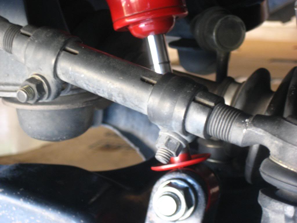
Below is where the other hook went, the track bar bracket; note the shiny golden bolt on the stock track bar bracket, that’s where I had to drill a hole in order to install the deluxe drop bracket kit:
A few cranks later and the track bar was back on and bolted up, I couldn’t believe how east that was. In my opinion, like the air cutter both of these Harbor Freight tools paid for themselves after using them for this job. If I had this come-along/hand winch from the beginning I would have saved myself so much time.
Finally everything was on and I could at least drive my truck now with an even lift on all four corners. Time to order the longer rear brake line and a LSPV (Load Sensing Proportioning Valve) Relocation Bracket.
Here’s the new Energy Suspension black polyurethane bushings on the rear sway bar end links (stock rubber bushings were squashed and had cracks throughout):
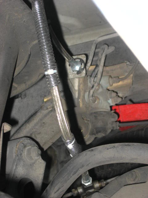
A couple of day’s later and the new Crown brake line is installed (I even got a free Marlin Crawler sticker with my order), brakes bled and the new 4” LSPV relocation bracket is on.
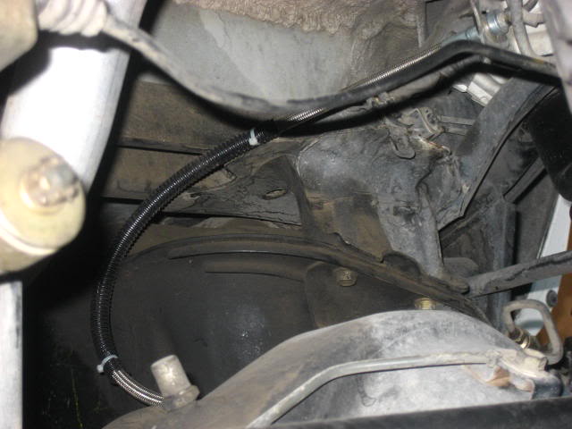
I put some wire loom around the brake line to help protect it from rubbing against the gas tank and the sway bar during rear suspension travel. You will have to get a bigger brake line clip to hold the Crown brake line on the Bracket next to the LSPV, the stock clip used on the OEM brake line is too small. Notice I used a big E-Clip I got from Ace Hardware.
Another view:
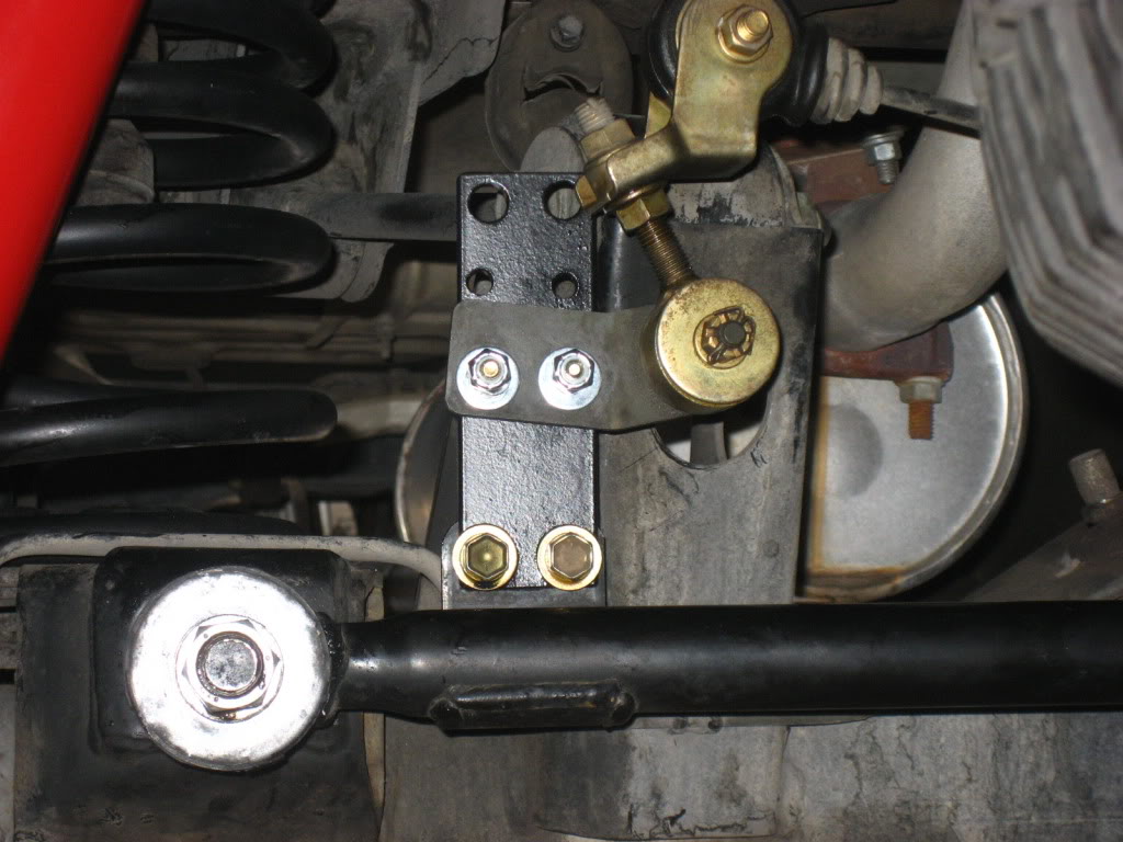
Below is the LSPV bracket with an extra set of holes that I drilled myself. The bigger holes at the top were pre-drilled. I drilled out the 4 holes below that; each spaced an inch apart vertically.
The bolts that hold the LSPV bracket to the track bar and the nuts that hold the pivot point link bracket are 2” apart, the same height as the spacers. My goal was to get the angle of the LSPV rod to how it was before the spacers were installed. That way no adjustments would be needed to the LSPV. I had to place 2 nuts in front of the LSPV bracket before bolting down the pivot point link bracket to allow for clearance during rear suspension travel.
Without the nuts acting as spacers the end of the link would scrape against the LSPV bracket (near the top right hole in the LSPV bracket).
If this truck ever get’s higher in the future I have 2 extra inches on this bracket to play with. After installing the LSPV bracket I did not notice any performance changes in the rear braking so I felt that there was nothing to adjust for on the LSPV itself. If felt as normal as it did before the lift.
Getting back to the 4” track bar drop bracket for a 2” rear coil lift, the custom size brackets are more expensive and take longer to ship as they are fabricated when ordered. Rodger usually always keeps a stock pile of the 4” brackets in stock. Besides me being cheap there’s a more important reason for me getting the 4” drop bracket. With all my emails to Rodger concerning my track bar (Panhard rod) issues he sent me this article on how the track bar angle should be on any vehicle…
http://www.popularhotrodding.com/tec...ide/index.html
As mentioned in the 13th paragraph of the article:
"The Panhard rod should be as long as possible and be mounted horizontal to the axle at static ride height. An angled Panhard rod will cause the axle to move sideways during suspension travel."
With this in mind and making the appropriate measurements as described on 4Crawler.com the logical choice for my truck was the 4” drop bracket. It’s also funny because of all my emails and troubles I permanently scared 4Crawlers website. He posted this article link along with a picture the next day as to how the track bar should look on the back of a 4Runner.
And here’s how mine came out in the end:
Notice above that my track bar is about as horizontal as it can get. The distance from the ground to the center of the track bar stud on the driver’s side compared to the distance from the ground to the center of the mounting bolt on the passenger side is within half of an inch of each other. This proves that just because you may have a 2” lift in the rear doesn’t mean that you automatically need a 2” drop bracket. Read on 4Crawler on how to correctly measure for your truck before you order!!
Below is the example that Rodger posted on 4Crawler.com because of all my troubles; the track bar is almost horizontal with the axle:
The scarring didn’t end there. Rodger would again be adding to his page. I had a few emails back and forth again with him concerning a banging noise form the rear end during moderate to heavy braking and moderate to heavy acceleration from a dead stop.
Under “check all fasteners in 100-200 miles to make sure they have not loosened” you’ll notice the sentence talking about the “clunking” noise. Well that’s what I had going on. By total coincidence my factory bottle jack somehow got loose in its mounts and started banging around while I was driving right after I completed everything on the rear end.
At first I couldn’t figure out what was going on and after multiple trips underneath the rear end and checking everything to make sure it’s tight I finally remembered that the factory bottle jack is directly behind me under the rear passenger seat, which is in the area where the noise was coming from. Sure enough it was the cause of the problem. I’ve never used that stupid thing anyway because I carry a mini floor jack with me at all times. It went on eBay the next day.
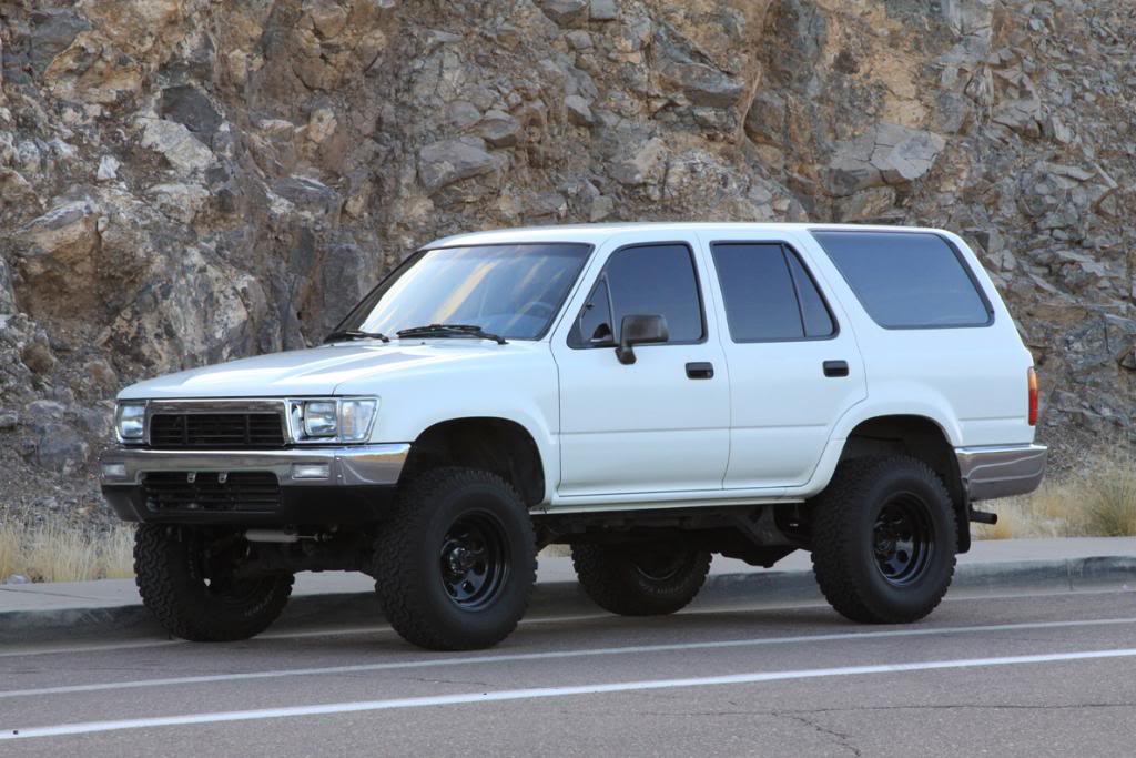
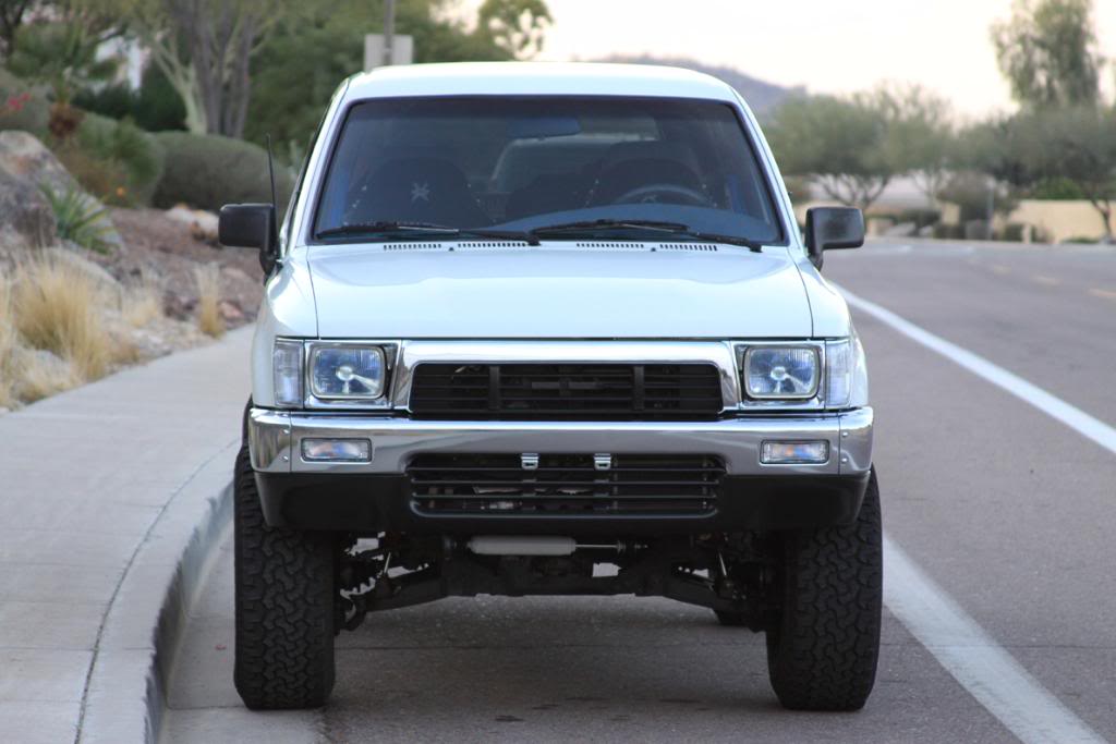
Above is before, below is after:
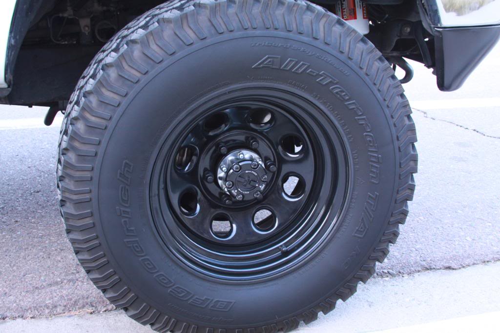
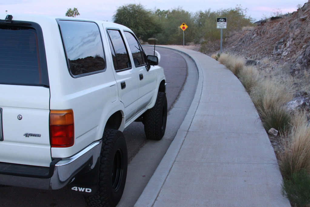
The 2” in lift is really mild however I could immediately tell that I was riding higher when I got in for the first time. It’s really visible by comparing the amount of space between the fenders and the tires when looking at the before and after shots.
Before the lift - Above is the measurement from the ground to the center of the front drivers side fender, below is the measurement from the ground to the center of the rear drivers side fender. 35.75” up front, 35” in the rear:
Before the lift - Above is measurement from ground to front driver’s side rocker panel, below is measurement from ground to rear driver’s side rocker panel. 19.5” up front, 20” in the rear:
After the lift - Above is the measurement from the ground to the center of the front drivers side fender, below is the measurement from the ground to the center of the rear drivers side fender. 37.5” up front 37.25” in the rear:
After the lift - Above is measurement from ground to front driver’s side rocker panel, below is measurement from ground to rear driver’s side rocker panel. 21” up front, 21.5” in the rear:
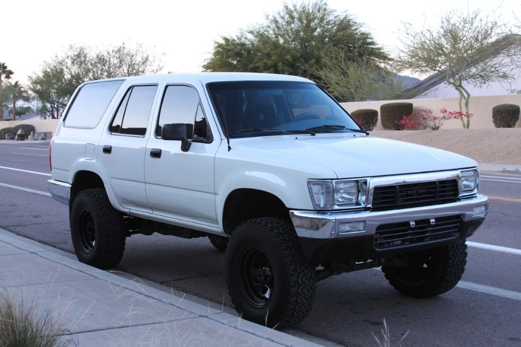
The truck looks level and it looks lifted evenly on all four corners. I also did not have to crank on the torsion bars since it lifted evenly but more importantly it sits evenly. I had thoughts about getting after market torsion bars, like a pair of Sway-A-Way’s but I was told that unless I have more weight up front (bumper, winch, engine swap, etc) the stock torsion bars will work just fine, especially since I mostly drive on the pavement. There’s no doubt that after 18 years the stock torsion bars are fatigued but they’re still working fine.
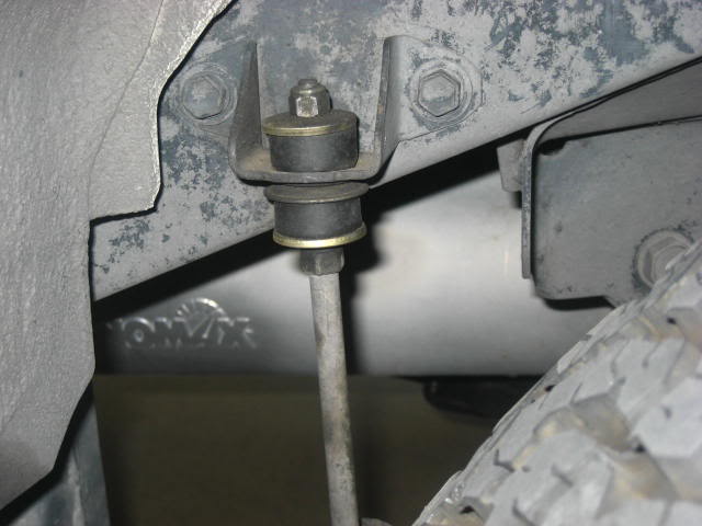
When I removed my shocks before the install I took the boots off of them, put the shocks back on and then made sharpie pen marks on the shafts out of curiosity to see what it would look like before and after.
Below shows my front shock shaft that I marked with a sharpie before installing the BJ spacers. Although I did not take measurement it looks like an extra inch of travel has been added. Judging by the space between the bump stop and lower control arm it looks like I have more than an inch if not the full 1.5” of new travel now. I plan to add some low profile bump stops from Energy Suspension soon, this way I can get a little more travel out of the front end:
The rear shock shafts became extended by 2” and my shocks still provided enough travel for the lift.
I actually installed this lift a few months ago and decided to use the test of time before I did a write up on my thoughts and experiences. Overall I think the truck looks better and it actually rides better too. The extra suspension travel has really made a noticeable difference. Hitting bumps in the road before that would cause the truck to really react or bottom out are handled a lot more smoothly now. The truck doesn’t bottom out as much as it once did. One example is driving over a section of cobble stone. My shocks might be working harder but I’m feeling less of it in the cab now. It also helps to have a good set of shocks on all four corners to keep the springs under control.
The last thing to do is to GET AN ALIGNMENT. By adding the BJ spacers all of the alignment angles on the front end are off…way off. Get this done right away to help save your tires and for safety when you’re driving down the road.
Also…Do not forget to check all fasteners as noted on 4Crawler under “check all fasteners in 100-200 miles to make sure they have not loosened”. I checked mine well over 200 miles and I had some hex bolts on both BJ spacers requiring a re-torque of 25ft. Ibs.
In the couple of months that I have been driving the truck I haven’t had any problems. Overall I have been really happy with the results from this project.
Special thanks to all who replied to my thread posts on Yotatech for help and especially to Rodger Brown from 4Crawler.com and Wabfab for the powder coating.
Below is the links that I posted during the install when I needed some extra advice…
https://www.yotatech.com/forums/f116...erence-189310/
https://www.yotatech.com/forums/f116...roblem-188670/
https://www.yotatech.com/forums/f116...ck-bar-186753/
Last edited by rworegon; 08-03-2014 at 03:03 PM.
 01-12-2010, 06:16 PM
#2
Registered User
Awesome write up! I don't even have a 2nd gen and I kept reading. Your rig looks sharp, I like the way you painted the hubs. Very cool. 
01-12-2010, 07:08 PM
#3
Contributing Member
wow that's som info there man!
great pics!
50,000 forum posting points to you!!!
but no really, good job man, and nice looking runner!

great pics!
50,000 forum posting points to you!!!
but no really, good job man, and nice looking runner!
Last edited by iamsuperbleeder; 01-12-2010 at 07:09 PM.


Trending Topics
01-26-2010, 12:53 PM
#11
Registered User
Thread Starter
Join Date: Apr 2008
Location: Glendale AZ
Posts: 292
Likes: 0
Received 0 Likes
on
0 Posts
YES. I just decided to run without it so I can show off my Rancho steering stabilizer that I found at the junkyard right after I installed the BJ spacers. I just like the look of it off now for driving in town. If I go off-road or in a lot of water I might throw it back on.
02-07-2010, 02:56 AM
#12
Registered User
Join Date: Dec 2003
Location: N37 39* W122 3*
Posts: 1,526
Likes: 0
Received 0 Likes
on
0 Posts
nice install...
but as a tip, carry a spare nut and bolt setup for this:
that one that hold the drop down bracket to the oem mount.
a few years ago, i saw a 4runner that broke down due to the bracket had broken loose because that bolt broke...
but as a tip, carry a spare nut and bolt setup for this:
that one that hold the drop down bracket to the oem mount.
a few years ago, i saw a 4runner that broke down due to the bracket had broken loose because that bolt broke...
06-16-2010, 05:40 AM
#18
Registered User
I installed the driver side BJ spacer last night, had no problems clearancing the UCA, but had hell getting the spacer & ball joint in, but I did fight it in the eventually. I did the socket between the bump stop trick, any other tips for tonight when I try the passenger side?
06-16-2010, 07:41 AM
#19
Registered User
Thread Starter
Join Date: Apr 2008
Location: Glendale AZ
Posts: 292
Likes: 0
Received 0 Likes
on
0 Posts
Thanks for all the compliments. To the unanswered questions - Rear coils are McQuay Norris from Checker Auto Parts. They're nothing special but they work great, just replacements for the sagging OEM's. They were a little cheaper then the Moog's so I got them, although I'm sure the Moog's are better quality.
I really like the Edelbrock IAS Shocks that I have. Too bad Edelbrock doesn't make them anymore. I really love the look of them, with the body bolted to the chassis and and the shock shaft pointing down, unlike all other shocks that are opposite. I've had them for 6 years now and put 95k on them. As far as I can tell they still work and they're not leaking. I called numerous manufactures awhile back...Edelbrock, Rancho, ProComp, etc. with one question and they all answered the same. I asked when they recommend changing there shocks out, is it like the average 60K like most OEM's? ALL of them said that if they're shocks are not leaking fluid then they should still be good.
My wheels are 15x8 Cragar Soft 8 (series 397, part # CRR-3975860). It has 4" backspacing and -12mm offset.
06-16-2010, 07:45 AM
#20
Registered User
Thread Starter
Join Date: Apr 2008
Location: Glendale AZ
Posts: 292
Likes: 0
Received 0 Likes
on
0 Posts
I can't really think of anything Yotarob2005. The passenger side will be just like the drivers side. What I did was I had the spacer resting on the ball joint and slowly jacked the lower arm up until the spacer hit the upper arm, then I just aligned the holes and bolted everything down. I did notice that it was easier after my cut was the proper shape, this way the spacer would easily fit in and tuck up inside the upper arm. I didn't really have to fight with anything after that casue everything lined up for me.


