dropzone's notebook of ideas, links, mods, misc BS
 01-29-2011, 02:21 AM
#81
TOyota Transmission gear ratios
Compliments of MarlinCrawler:
http://www.marlincrawler.com/tech/tr...ar-ratio-chart
Trans Date .. 1st 2nd 3rd 4th 5th 6th Rev T/Case Output Spline T/C Shift Notes
L43 1979-80 3.670 2.110 1.451 1.000 4.180 Gear 21-spline Top Shift 20.875", side shifting
L45 1981-82 3.928 2.333 1.451 1.000 4.743 Gear 21-spline Top Shift 20.875"
L50 1981-82 3.928 2.333 1.451 1.000 0.851 4.743 Gear 21-spline Top Shift 20.875" long, 75x19mm input bearing
L52 1983 .....3.928 2.333 1.451 1.000 0.851 4.743 Gear 21-spline Top Shift 20.875" long, 80x20mm input bearing
G52 1984-86 3.928 2.333 1.451 1.000 0.851 4.743 Gear 21-spline Forward 25.5" long, 80x20mm open-face input bearing
G54 1986-88 3.928 2.333 1.451 1.000 0.851 4.743 Gear 21-spline Forward 25.5" long, 80x23mm sealed input bearing
G58 1989-95 3.928 2.142 1.397 1.000 0.851 4.743 Chain 26-spline Forward 25.5" long, front vacuum disconnect
W55 1984-88 3.566 2.056 1.384 1.000 0.850 4.091 2WD Applications
W56-A 1985 3.954 2.141 1.384 1.000 0.850 4.091 Gear 21-spline Top shift 25.5" long, Aluminum Center Section
W56-B 1986-88 3.954 2.141 1.384 1.000 0.850 4.091 Gear 21-spline Top shift 25.5" long
W56-C 1989-91 3.954 2.141 1.384 1.000 0.850 4.091 Gear 21-spline Forward shift 25.5" long
W56-D 1992 3.954 2.141 1.384 1.000 0.850 4.091 Gear 21-spline Forward shift 25.5" long
W56-E 1993-95 3.954 2.141 1.384 1.000 0.850 4.091 Gear 21-spline Forward shift 25.5" long
W59 1995-05 3.954 2.141 1.275 1.000 0.850 4.091 Chain 26-spline Top Shift 25.5" long
R150F 1988-91 3.830 2.062 1.436 1.000 0.838 4.220 Chain 23-spline Top Shift
R150F 1992-95 3.830 2.062 1.436 1.000 0.838 4.220 Chain 23-spline Top Shift
R150F 1995-05 3.830 2.062 1.436 1.000 0.838 4.220 Chain 23-spline Top Shift
R151F 1986-87 4.313 2.330 1.436 1.000 0.838 4.843 Gear 23-spline Forward Shift 22R-TE Turbo
MAR515 1986-05 5.15 2.740 1.930 1.000 0.830 23-spline
R154 1986-92 3.250 1.955 1.310 1.000 0.753 Toyota Supra Turbo
R61F 2005+ 4.171 2.190 1.488 1.193 1.000 0.799 3.607 Chain 19-spline Top Shift 26.25" long
A340 1985-95 2.804 1.531 1.000 0.705 2.393 4spd Automatic
AX-5 1984-02 3.92 2.33 1.44 1.000 0.85 4.74 21-spline Cherokee, Comanche, and Wranglers
AX-15 1989-99? 3.83 2.33 1.44 1.000 0.79 4.22 23-spline Cherokee, Comanche, and Wranglers
Toyota Transmission Picture Link
http://www.marlincrawler.com/transmi...built-complete
more info:
some of this info might be duplicated in this thread but throwing more info..
some pertinent to 1st Gens specifically;
ID'ing L50 and L52 transmissions
Check out our Transmission Input Bearing Identification Chart at the bottom of this page.
L45 4-speed (what you have) and a L50 5-speed both use either a 63/32N input bearing or a 032-2.
The L52 5-speed, which was only available in 1983, has a slightly stronger input bearing with either B32-14UR or 32BC08S1N part number written on the bearing race.
You will need to remove the nose cone from the transmission to expose and read the numbers from the input bearing race.
Really pulling the front nose cone is going to be the best way to ID the transmission.
Regards,
BigMike
Bingo. But you'll never know what the previous owner did to the truck and it's possible someone could have slapped in a L50 junkyard special into their '83 Hilux.
There actually is a way to know if the transmission is from an 83 simply by reading the serial number stamped into the bottom of the cast iron housing. If the first and second digits are 211 or 212, or if the first number is a 3, then 100% no questions asked it is a L52.
Regards,
BigMike
There actually is a way to know if the transmission is from an 83 simply by reading the serial number stamped into the bottom of the cast iron housing. If the first and second digits are 211 or 212, or if the first number is a 3, then 100% no questions asked it is a L52.
Regards,
BigMike
Quoted from PBB:
Pickup and 4Runner Transmissions with 1st gear ratios.
L43 4 speed 79 - 80 3.67
L45 4 speed 81 - 82 3.93
L50 5 speed 81 - 82 3.93
L52 5 speed 83 3.93
G52 & G54 5 speed 84 - 88 (Carb) 3.93
W56 5 speed 85 - 95 (EFI) 3.95 Manual Hub Equipped Vehicles 89 and up Have W56, 89 and up ADD vehicles have G58.
R151F 5 speed 86 - 87 (turbo only) 4.31
G58 5 speed 89 - 95 3.93 ADD Equipped Vehicles
R150F (6 cyl) 5 speed 88+ 3.83
Identification:
G52/54 84-88' are twin stick, use a 8 bolt center section, 6 bolt gear t/case pattern, 21 spline output.
G58 89-95' twin stick, 8 bolt center, 9 bolt chain t/case, 26 spline
W56 85-88' (single stick), 89-95' (twin stick), 10 bolt center, 6 bolt t/case, 21 spline
R151F 86 - 87 (turbo only) will have two housings of four bolts each just like a G52, the difference would be the large rubber plug on the bottom of the bellhousing.
Info provided by Marlin Crawler
All 84 to 95 22R trans are 25.5" long including the bellhousing. The only shorter trans is the 79-83 year trans which are 20.75" long with bellhousing. These early short trans have had a poor service record due in part to their small bearings and lighter gears. The 82-83 L52 5 speed which had a 80 x 20 mm front input bearing has had the best service record. A number of years ago, I invented a way to install a oversize 80 x 23 mm input bearing with an inproved gear set which features a greater helix angle for added strenght. I call it my L52HD and is the strongest 20.75" long trans.
Last edited by dropzone; 07-07-2011 at 01:07 AM. Reason: removed duplicate info
 01-29-2011, 05:19 AM
#82
Registered User
whoa thanks 4crawler, been looking for this for a while now. Don't like the 3-4 shift in my g54???? Not that there is anything wrong with the trans just seem to me like too big of a jump.
 02-22-2011, 07:01 AM
#84
Guage Swap
83 did a great job on getting this info:
https://www.yotatech.com/forums/f114...e-swap-164182/
https://www.yotatech.com/forums/f114...e-swap-164182/
Part of this was posted by others over at the Marlin site, but I added to it & figure we could use our own swap thread over here in the pre-84 area. I think '79-81 trucks are different, but if you have an '82 or '83 with the "newer" style gauge, this will work.
**EDIT: The person who made this list came up with the numbers by counting every slot in the plug. The FSM numbers them differently because it only counts slots that have a wire in them, so don't try to compare the two or you'll get confused like I did!
It also seems better to use the wire #, as opposed to color, since some seem to be different. I'll post at the end of this thread what wire color I've got in what #slot. For that part I used the numbers from the FSM, not from this list below. Feel free to post here or PM me with any questions.
SR5----------Non-SR5---------Wire Color----Function
1<-----------------1-------------->GY------------>Right turn signal
2
3<-----------------3-------------->BR(B BR)------->Speed Sensor (-)
4<-----------------6-------------->GL------------->Speed Senson (+)
5
6
7<-----------------23------------->YG-------------->Water Temp
8<-----------------9-------------->RW-------------->Panel Lights (+)
9<----------------15-------------->YR--------------->Fuel Gauge
10<---------------12-------------->Y---------------->Ignition switch power
11<---------------21-------------->YB--------------->Oil Idiot Light
12<---------------22-------------->YW-------------->Charge Light
13<---------------14-------------->WB-------------->Ground
14<--------------------------------------------------Tach-must run a wire
15<---------------17----------------GB---------------Left Turn Signal
16----------------16----------------RB---------------Panel Lights (-)
17
18
19<---------------11---------------G-------------------4wd
20
21<---------------19---------------BY------------------Seat Belt
22
23<---------------13---------------RG------------------High Beam
24<---------------20---------------GW-----------------Brake
So if you get an SR5 cluster and simply plug it in to your truck, any of these wires that aren't the same number won't work. When I just plugged my cluster in, the right turn signal was all that worked. So you need to pull the wires from the corresponding number out of the plug and re-insert them into the SR5 location.
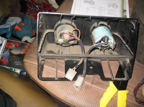
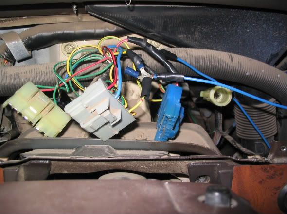
This shows what the back of the cluster looks like and the wire numbers. It also, if you can see it, shows you where the separate oil & volt cluster hooks in.
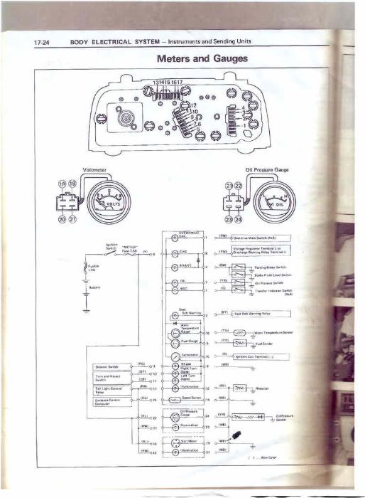
So to get the oil gauge & voltmeter working, you need to splice into the main cluster wires. You could get away with just splicing into hot wires here and there, but I liked doing it the way it would have been if it had been wired for it from the factory.
Back of gauges
Cut & labled
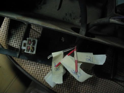
Connectors
My voltmeter ended up having some different wire colors than the FSM page listed, but they were all in the right location in the plug, so it was easy to figure out.
What I came up with after looking over the diagram is this, as far as what wires to tie the mini-cluster into:
Mini-------------Main
19 & 21(oil)---------->17
18 & 22-------------->6
21(volt) & 23--------->12
24------------------->Oil sending unit (SR5 model for GAUGE, not idiot light)
20------------------->Ground
Notice there is a #21 in each gauge for some reason.
If you want the oil idiot light and gauge to work, you need both sending units; one hooked up to the main cluster (switch), one hooked up to the new oil gauge (gauge). I just left the idiot light out..
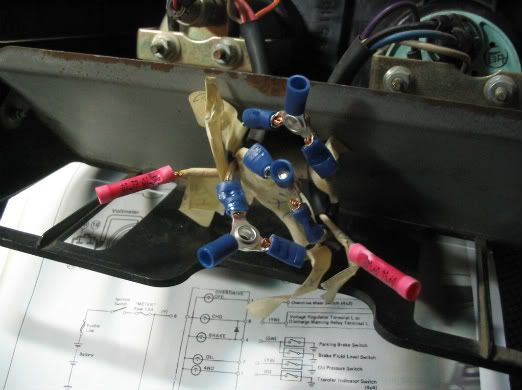
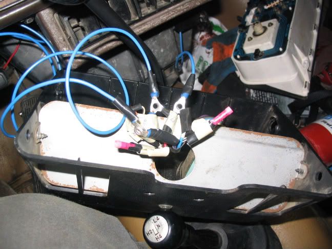
Splicing into main cluster
Connecting to mini-cluster (I used 16 gauge wire)
I'll need to pull the part that connects the wire to the oil sending unit off a truck in a junk yard & splice it in, but for now I just have the wire wrapped around the sending unit and it works fine, but I'm guessing it'll eventually vibrate off if I leave it that way. That's it, mine works great.

***Here are my wire color locations (using the FSM slot #'s)
1___2___3___4___
G___BY__RG__GW
5___6___7___8___9___10___11___12
YR__Y___YB__G__WB__Tach_GB___RB
13___14___15___16___17
GY__Br____GL___YG__RW
Remember, B is black, Br is brown, L is blue.
**EDIT: The person who made this list came up with the numbers by counting every slot in the plug. The FSM numbers them differently because it only counts slots that have a wire in them, so don't try to compare the two or you'll get confused like I did!
It also seems better to use the wire #, as opposed to color, since some seem to be different. I'll post at the end of this thread what wire color I've got in what #slot. For that part I used the numbers from the FSM, not from this list below. Feel free to post here or PM me with any questions.
SR5----------Non-SR5---------Wire Color----Function
1<-----------------1-------------->GY------------>Right turn signal
2
3<-----------------3-------------->BR(B BR)------->Speed Sensor (-)
4<-----------------6-------------->GL------------->Speed Senson (+)
5
6
7<-----------------23------------->YG-------------->Water Temp
8<-----------------9-------------->RW-------------->Panel Lights (+)
9<----------------15-------------->YR--------------->Fuel Gauge
10<---------------12-------------->Y---------------->Ignition switch power
11<---------------21-------------->YB--------------->Oil Idiot Light
12<---------------22-------------->YW-------------->Charge Light
13<---------------14-------------->WB-------------->Ground
14<--------------------------------------------------Tach-must run a wire
15<---------------17----------------GB---------------Left Turn Signal
16----------------16----------------RB---------------Panel Lights (-)
17
18
19<---------------11---------------G-------------------4wd
20
21<---------------19---------------BY------------------Seat Belt
22
23<---------------13---------------RG------------------High Beam
24<---------------20---------------GW-----------------Brake
So if you get an SR5 cluster and simply plug it in to your truck, any of these wires that aren't the same number won't work. When I just plugged my cluster in, the right turn signal was all that worked. So you need to pull the wires from the corresponding number out of the plug and re-insert them into the SR5 location.
This shows what the back of the cluster looks like and the wire numbers. It also, if you can see it, shows you where the separate oil & volt cluster hooks in.
So to get the oil gauge & voltmeter working, you need to splice into the main cluster wires. You could get away with just splicing into hot wires here and there, but I liked doing it the way it would have been if it had been wired for it from the factory.
Back of gauges
Cut & labled
Connectors
My voltmeter ended up having some different wire colors than the FSM page listed, but they were all in the right location in the plug, so it was easy to figure out.
What I came up with after looking over the diagram is this, as far as what wires to tie the mini-cluster into:
Mini-------------Main
19 & 21(oil)---------->17
18 & 22-------------->6
21(volt) & 23--------->12
24------------------->Oil sending unit (SR5 model for GAUGE, not idiot light)
20------------------->Ground
Notice there is a #21 in each gauge for some reason.
If you want the oil idiot light and gauge to work, you need both sending units; one hooked up to the main cluster (switch), one hooked up to the new oil gauge (gauge). I just left the idiot light out..
Splicing into main cluster
Connecting to mini-cluster (I used 16 gauge wire)
I'll need to pull the part that connects the wire to the oil sending unit off a truck in a junk yard & splice it in, but for now I just have the wire wrapped around the sending unit and it works fine, but I'm guessing it'll eventually vibrate off if I leave it that way. That's it, mine works great.
***Here are my wire color locations (using the FSM slot #'s)
1___2___3___4___
G___BY__RG__GW
5___6___7___8___9___10___11___12
YR__Y___YB__G__WB__Tach_GB___RB
13___14___15___16___17
GY__Br____GL___YG__RW
Remember, B is black, Br is brown, L is blue.
02-23-2011, 05:53 PM
#85
-22RE--22RTE differences
Turbo22RTE Forum:
http://www.22rte-trucks.com/simplemachinesforum/
Transmission:
turbo trucks came with stronger transmissions and transfercases with 23 spline shafts vs. the stock 21 spline shafts of normal trucks.
R151F 1986-1987 22RTE (pickups only)
5 speed,
first gear: 4.31
length 25 1/4" Top
(w/ Bucket Seats)
Forward (w/ Bench Seats)
Can be identified by round rubber plug on the bottom of the bellhousing.
the compression ratios and heads are different:
Compression Ratio: 9.3:1 (7.5:1 RET)
head differences:
you do realize the 22re head is quite different then the 22rte head right?
1985 - 1995 22R-22RE Cylinder Head
Square Intake Port
Pear Shape Exhaust Port
52/54 C.C. Combustion Chamber
82/83 C.C. Chamber (Turbo)
Intake Valve Diameter 44.5mm
Exhaust Valve Diameter 36.5mm
1985 - 1995 22R-22RE Cylinder Head
Square Intake Port
Pear Shape Exhaust Port
52/54 C.C. Combustion Chamber
82/83 C.C. Chamber (Turbo)
Intake Valve Diameter 44.5mm
Exhaust Valve Diameter 36.5mm
02-23-2011, 06:56 PM
#86
Registered User
Centramatic wheel balancers...4Crawler is the only member I am aware of that runs these things, they are basically automatic wheel balancers, no need to have a butt load of lead on your wheels or running air soft pellets or something like that, truckers have reported getting 200K out of a set of tires.
I figure with the rock rash my tires have, they would transfer to other sets of tires/truck...help eliminate some handling issues these are kind of must have at some point. I have thrown a wheel weight a few times.
They are $199 plus shipping
Centramatic FAQ: http://www.centramatic.com/Page.aspx?page=FAQ
how they work:
http://www.youtube.com/watch?v=ullnFQD4F1I
04-18-2011, 02:12 PM
#87
79-83 gas tank information, auxillary tank options
gas tank comparison
long bed on Top-37.5 " long 16 gal
short bed on bottom, 30.25" 13.5 gal.

Gas line (To tank) Routing: From the 1981 Service Manual:

************************************************** *******
22 gallon replacement gas tank for 80-83:
NorthWest Metal Products
Make: Toyota
Model: SWB Pick-up 2 & 4 Wheel Drive 1980-1983
Part Number: TPR-4
Type: Replacement
Size: (Gallons) 22
Price: $556.00
INCLUDES: Mounting Hardware-Gauge Modification Material Kit.
************************************************** ************************************************** **
auxillary replacement tank options:
adding some info for further research/reference:
from the ford gas tank thread on pirate
long bed on Top-37.5 " long 16 gal
short bed on bottom, 30.25" 13.5 gal.
Gas line (To tank) Routing: From the 1981 Service Manual:
************************************************** *******
22 gallon replacement gas tank for 80-83:
NorthWest Metal Products
Make: Toyota
Model: SWB Pick-up 2 & 4 Wheel Drive 1980-1983
Part Number: TPR-4
Type: Replacement
Size: (Gallons) 22
Price: $556.00
INCLUDES: Mounting Hardware-Gauge Modification Material Kit.
************************************************** ************************************************** **
auxillary replacement tank options:
adding some info for further research/reference:
from the ford gas tank thread on pirate
Here's anothers to use:
GEO TRACKER 1996
GALLON: 11
DIMENISON: 27 3/8 x 13 1/2 x 10
1994-1997 Toyota Corolla
13 Gal.
(23 x 37-1/2 x 8 1/2"),
1985-94, FUEL TANK, S10 BLAZER, S15 JIMMY, (W/ FI),
Dimension: 33" x 22" x 8-7/8"
Gallons: 13.2
87-91 Toyota Camry Gas Tank 13.5 Gal
Capacity: 13.5 Gallons/51 Liters
Dimensions: 38 X 23 1/2 X 8 inches
1985-87 Gas Tank 14 Gal GTS Coupe
Capacity: 14 Gallons/52 Liters
Dimensions: 33 1/8 X 21 X 9 1/2 inches
GMC S-15 Jimmy Gas Tank 13.2 Gal 2.5L 2.8L 85-87
US Gallon 13.2
Liter 50.0
Size 33" x 22" x 8 7/8"'
I just spent some time looking at Ford tanks. I think there's some confusion on these... :confused:
The e250 tanks were supposedly 34x23x9", but I couldn't find one like that.
I ended up with a rear tank from a '93 F150. It measures 34.5" x 26.5" x 8". It looks exactly the same as the one Harry put in his truck, but I never actually measured his and I'm not sure he did either. I'm not sure it holds 22 gallons, seems too small.

the ones I found from Ford vans looked like the pictures clutter1 posted and measured 34" x 23" x 11". This one is probably the 22 gallon one (definitely holds more than the one above anyway). Good size, but thicker than I wanted.
The F150 tank is nice and thin and shouldn't hang down much. Its actually a little less than 8" thick at the thick end, and the other end is closer to 7". Unfortunately, putting the thin end towards the rear to minimize dragging also puts the filler on the wrong side. I guess I'll see how it works out...
Hopefully this info will help somebody.
The e250 tanks were supposedly 34x23x9", but I couldn't find one like that.
I ended up with a rear tank from a '93 F150. It measures 34.5" x 26.5" x 8". It looks exactly the same as the one Harry put in his truck, but I never actually measured his and I'm not sure he did either. I'm not sure it holds 22 gallons, seems too small.
the ones I found from Ford vans looked like the pictures clutter1 posted and measured 34" x 23" x 11". This one is probably the 22 gallon one (definitely holds more than the one above anyway). Good size, but thicker than I wanted.
The F150 tank is nice and thin and shouldn't hang down much. Its actually a little less than 8" thick at the thick end, and the other end is closer to 7". Unfortunately, putting the thin end towards the rear to minimize dragging also puts the filler on the wrong side. I guess I'll see how it works out...
Hopefully this info will help somebody.
Last edited by dropzone; 09-26-2011 at 11:36 AM. Reason: added info
04-18-2011, 02:33 PM
#88
OldDirtyDirt did a nice write up on converting square to round headlights
This can be used to go round to rectangular too..
Parts you will need:
-two headlight aprons (doors, bezels) of the kind you want
appropriate grill (79-81 grills are not compatible with rectangular headlight -aprons and vice versa with out hacking stuff up)
-2 headlight buckets (round or rectangular)
-side marker lenses (again they are specific to the headlight style)
-head light lenses assemblies (now is a good time to updgrade to H4 style housings)


Side marker lights will need plugs swapped:


This can be used to go round to rectangular too..
Parts you will need:
-two headlight aprons (doors, bezels) of the kind you want
appropriate grill (79-81 grills are not compatible with rectangular headlight -aprons and vice versa with out hacking stuff up)
-2 headlight buckets (round or rectangular)
-side marker lenses (again they are specific to the headlight style)
-head light lenses assemblies (now is a good time to updgrade to H4 style housings)
Side marker lights will need plugs swapped:
05-01-2011, 11:39 AM
#89
Differential breather extension/part numbers
Been meaning to post this for awhile, a recent thread reminded me:
Simpler answer use one of these part numbers and attach a preferred length rubber hose and a universal oil breather filter on the end.
Nissan Part number 38323-C6010
Toyota 90404-51319: for 3/8� Barb
Toyota 90404-51026: for 1/4� hose
Nissan 38323-C6010: for 3/16� hose
or a standard 1/8" NPT to 1/4" hose barb fitting. as 4crawler mentioned it's not a perfect fit but his worked well.
Toyota part number for the OEM breather is 90930-03031
05-01-2011, 12:21 PM
#90
Registered User
wow I think that's twice I made it into your thread.
but anyway, those part numbers came from this: http://www.sonoransteel.com/includes...ther_Parts.pdf
but anyway, those part numbers came from this: http://www.sonoransteel.com/includes...ther_Parts.pdf
06-22-2011, 08:08 AM
#92
saw this in Outsane's 4Runner build..gonna borrow this for rear seat belts in my Trekker:

Rear seat belts will now bruise your shoulders along with you hips in the event of a sharp deceleration!
link to more info about these belts
https://www.yotatech.com/forums/f116...-belts-214268/
Rear seat belts will now bruise your shoulders along with you hips in the event of a sharp deceleration!
link to more info about these belts
https://www.yotatech.com/forums/f116...-belts-214268/
07-05-2011, 10:40 PM
#93
Registered User

Join Date: May 2009
Location: Kelso, WA
Posts: 73
Likes: 0
Received 0 Likes
on
0 Posts
Didn't want to quote the whole post to get the information across, but this is in reference to the L50/52 scenario...
L52's were NOT an 83 model year only transmission!!
The engine data plate in my 81 that I just sold last week very clearly stated that it was factory equipped with an L52 transmission.
L52's were NOT an 83 model year only transmission!!
The engine data plate in my 81 that I just sold last week very clearly stated that it was factory equipped with an L52 transmission.
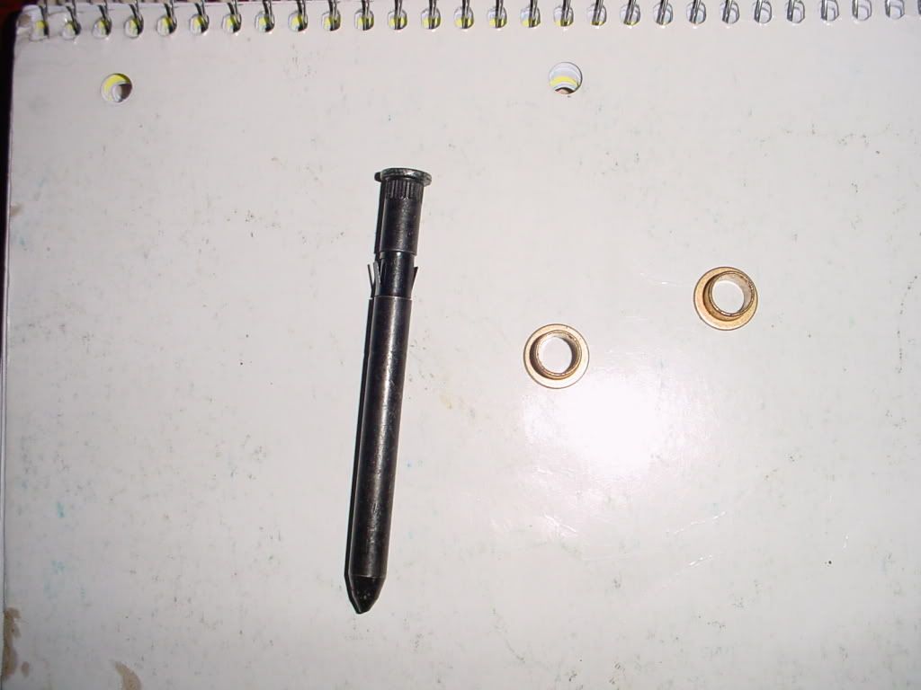
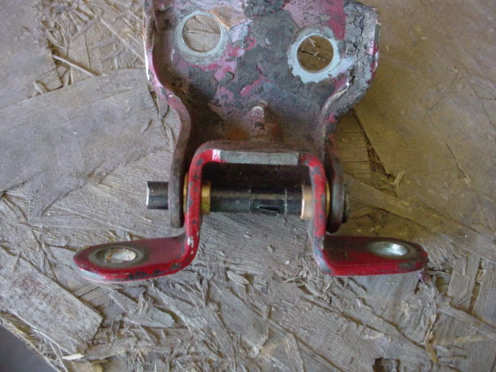
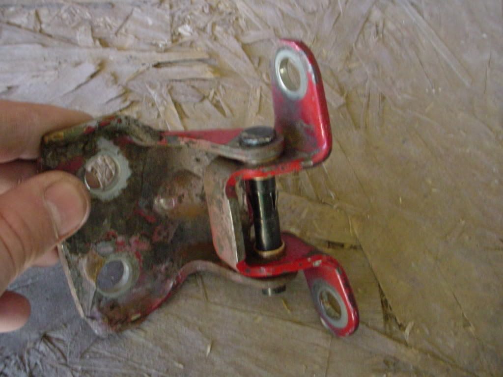
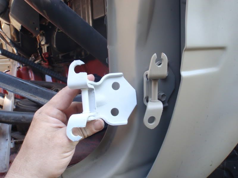
07-07-2011, 01:04 AM
#94
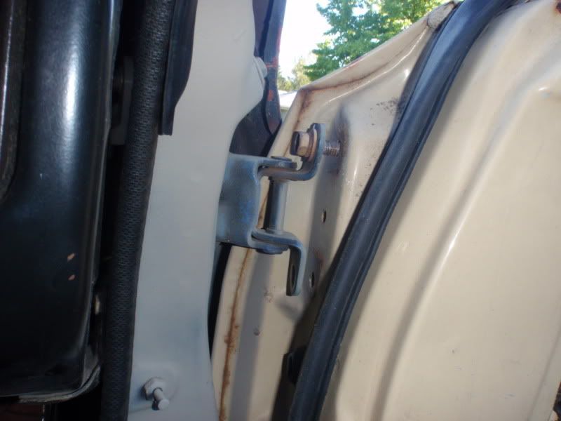
Door Hinge Pin replacement/Quick Release Door mods
consolidating some info on door pin replacement and quick release hinges for half doors or tube doors:
wheatus did a nice write up on replacing door hinge pins
**If you go this route, use the hinge version of the right, not the left***
Video How to sent in by 87hillbillyoter
wheatus did a nice write up on replacing door hinge pins
It seems that you can purchase lower door hinge replacements but not upper hinges. I modified my hinges to use replacable pins and bushings. To do this modification you will need: 12mm socket, ratchet, at least 3 inch extension, files or grinding tool, hammer, punch, vise, hacksaw, and a helper. (I will try and get the part numbers of the pins and bushings i used. I took my hinges to the parts store after i removed the old pins and bushings and found something close.)
1. Roll down the window, it makes the door easier to handle when removed.
2. If not equiped with power windows or locks skip to step 4.If equipped with power options you will need to remove the kickpanel and disconect the wiring.
3. Pull the wiring through the A pillar.
4. Using the ratchet, extension, and 12mm socket remove one bolt from each hinge.
5. Have your helper hold the door as you remove the last two bolts.
6. Remove the 4 bolts holding the hinges to the door shell. There should be a total of 8 bolts.
7. Place the door shell in a place where it will not get damaged.
8. Take pictures or mark the hinges top and bottom to aid reassembly later. Work on one hinge at a time so you do not mix parts.
9. Secure the hinge in a vise.
10. Using a flat file or a grinding tool, a dremel or a die grinder work well, to grind the puddle weld holding the pin. Be careful not to grind too much off of the hinge.
11. Use the punch and hammer to knock the pin out of the hinge.
12. Remove the old bushings.
13. File, drill, or grind the hinges to fit the new pins and bushings. Notice that not all of the holes are the same size, check the fitting often.
14. Line up your marks or refer to your picture for reassembly.
15. Install new bushings.
16. Install new pin.
17. Reassemble the hinge.
18. Using the hacksaw you can cut off the excess pin. (optional)
19. Repeat steps 8-18 for the other hinge.
20. Reinstall the hinges to the door shell.
21. Have helper hold the door as you mount the hinges to the body.
Video How to sent in by 87hillbillyoter
Originally Posted by 87hillbillyoter
07-11-2011, 02:11 PM
#95
1st Gen Plug Differences: 79-81 vs 82-83
so just because you have a 1st Gen truck, there are differences between the 79-81 and 82-83 that are not as obvious as the round and rectangular headlights;
Found this when swapping steering columns today:
the light/wiper switches look the same-
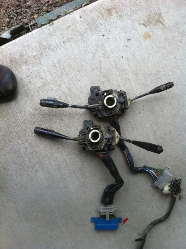
81 switch plug in on top, 82-83 is on the bottom
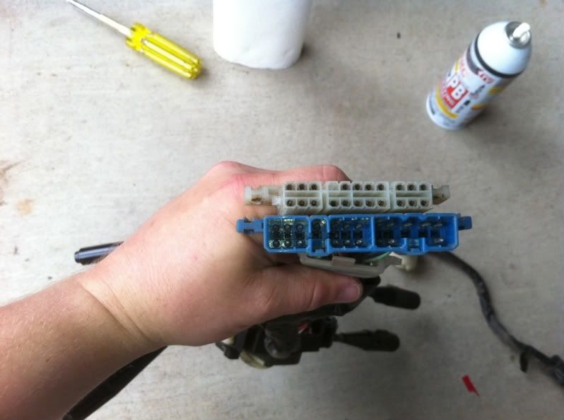
I will try to post more plug differences...
Found this when swapping steering columns today:
the light/wiper switches look the same-
81 switch plug in on top, 82-83 is on the bottom
I will try to post more plug differences...
07-12-2011, 06:09 PM
#96
Registered User

Join Date: Jul 2009
Posts: 123
Likes: 0
Received 0 Likes
on
0 Posts
I am very interested in this. Ive always wanted to put intermediate wipers on my truck. I hate the only low and high option. I wonder if there is anything else than to just swap the controls.
08-29-2011, 09:11 PM
#98
Tuning a weber 32/36 series Carb
From this thread:
https://www.yotatech.com/forums/f120...2-36-a-240521/
Other helpful links:
Subject: weber carb info
weber carb tuning:
http://www.clutchkitcenter.com/media...weber/K610.pdf
˟
http://board.marlincrawler.com/index.php?topic=62976.0
˟
trouble shooting guide:
http://www.webercarbsdirect.com/v/vs...ng%20Guide.pdf
˟
carb adjustment guide:
http://www.cjclub.co.il/files/Weber3236adjust.pdf
˟
jetting:
http://www.bmw2002faq.com/content/view/62/32/
˟
parts diagram/exploded view:
http://www.redlineweber.com/html/Tec..._breakdown.htm
http://www.webercarbsdirect.com/v/vs...3236DGAVEV.pdf
˟
˟
carb set up and lean best idle set up:
http://www.redlineweber.com/html/Tec...lean_best_.htm
˟
˟
https://www.yotatech.com/forums/f120...2-36-a-240521/
Someone please sticky this.
NOTE: This ONLY goes for the 32/36 DGV/DGEV/DGAV etc series of carburetors not the 38.
This procedure assumes no modifications have been done internally to the carburetor. Including but not limited to primary and secondary main jets, air corrector jets.
It also assumes you have no vacuum leaks ANYWHERE including the popular two-piece adapter that typically comes with the kits. I HIGHLY suggest using the Transdapt 1 piece adapter. Others have had decent results with the LCE spiral adapter as well, even though that is also a two-piece unit. Easy way to test for vacuum leaks at the adapter is to spray carb cleaner in and around the entire base of the carburetor. If a change in idle (usually a stumble) is noticed then the adapter is leaking air into the engine and needs to be fixed before any accurate tune is achieved.
Other common areas for vacuum leaks are Valve cover gasket, oil pan gasket and timing cover gaskets.
It is important to follow all linkage and lever installation instructions. The number one and two reasons for tuning errors are improper linkage installations and over tightened linkage nut, causing a binding in linkage assembly.
CALIBRATIONS MAY VARY DUE TO REGIONAL FUELS AND STATE OF ENGINE TUNE AND PERFORMANCE. POOR RUNNING QUALITY DOES NOT MEAN A DEFECT IN THE CARBURETOR. AN ADVANTAGE OF THE WEBER CARBURETOR IS ITS EASE OF ADJUSTMENT AND TUNING.
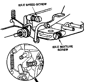
SET UP ADJUSTMENTS
Start set up by confirming carb base line settings. Do not depend on the factory delivered settings. Check them before the carb is installed.
All settings are done with choke disengaged or warmed up so that the choke is fully opened and disengaged. This is done on automatic choke carburetors by first opening the choke butterfly by hand and inserting a wood block or wedge of some kind to hold open while the linkage is cycled (linkage operated through its full movement ) to clear the choke cam. (You will hear a metallic click as the cam is released. You can check the fast Idle screw under the choke assembly to confirm that it is not in contact with the choke fast idle cam.)
Set the Idle stop screw (speed screw see fig 1) by backing out the Idle speed screw until it is not in contact with the throttle stop lever. Cycle the linkage again to be sure that the linkage comes to close without any assistance. (Checking for linkage bind) Now bring screw back into contact with the lever and continue to open or screwing in 1 turn no more than 11/2 turns.
Set the mixture screw (see Fig 1) by first screwing in until the screw stops, bottoms out.
DO NOT FORCE OR BIND AS THIS WILL CAUSE DAMAGE TO THE SCREW AND IT’S SEAT IN THE BODY OF CARBURETOR.
Back out the screw 2 full turns.
TUNING
Simple Rules for low speed calibration
If the mixture screw is more than 2 1/2 turns out turns then the Idle jet is too lean (too Small). When the mixture screw is less than 11/2 then the Idle jet is too rich (too large). These assumptions are based on the fact that the speed screw setting is not opened more than 11/2 turns. If the speed screw has to be opened 2 or more turns then this is also an indication of a lean condition usually requiring greater change. At times it may appear to be showing signs of richness or flooding it is really a lean condition. See pictures and notes in the tech 2 article supplied in the kit instructions, view and please understand the need to keep throttle plate as near to closed as possible so as not to prematurely expose the transition holes. This is what causes the visible rich condition, and confirms the need to increase the jet size.
JET KITS are available if needed.
EXAMPLE: With the speed screw set at no more than (1 1/2) turns in after contact with the stop lever; and the best idle occurring with the mixture screw set at 3 turns from bottom, indicates the need for a larger Idle jet. Achieving the best idle at under 2 turns indicates the need for a smaller idle jet.
The secret to understanding the critical nature of the carburetor set up and the advantages of a WEBER over other carburetors is the Idle circuit. Referred to as the low speed circuit by Weber, this circuit is responsible for 80% of the driving operation. This is the reason that the Weber should give a fuel economy improvement over most factory carbs along with significant performance gains. In the worst case you should not see a significant fuel economy loss over stock, while improving HP & Drivability.
The Weber Carburetor is a sequentially timed device to the motor like the distributor. Time taken in the setup will provide more fun later.
NOTE: This ONLY goes for the 32/36 DGV/DGEV/DGAV etc series of carburetors not the 38.
This procedure assumes no modifications have been done internally to the carburetor. Including but not limited to primary and secondary main jets, air corrector jets.
It also assumes you have no vacuum leaks ANYWHERE including the popular two-piece adapter that typically comes with the kits. I HIGHLY suggest using the Transdapt 1 piece adapter. Others have had decent results with the LCE spiral adapter as well, even though that is also a two-piece unit. Easy way to test for vacuum leaks at the adapter is to spray carb cleaner in and around the entire base of the carburetor. If a change in idle (usually a stumble) is noticed then the adapter is leaking air into the engine and needs to be fixed before any accurate tune is achieved.
Other common areas for vacuum leaks are Valve cover gasket, oil pan gasket and timing cover gaskets.
Carburetor Set Up and Lean Best Idle Adjustment
Base line Settings
Speed Screw 1 to 11/2 turns
Mixture Screw 2 turns
Your settings with engine runningMixture Screw 2 turns
Speed Screw ____________
Mixture Screw ___________
Mixture Screw ___________
It is important to follow all linkage and lever installation instructions. The number one and two reasons for tuning errors are improper linkage installations and over tightened linkage nut, causing a binding in linkage assembly.
CALIBRATIONS MAY VARY DUE TO REGIONAL FUELS AND STATE OF ENGINE TUNE AND PERFORMANCE. POOR RUNNING QUALITY DOES NOT MEAN A DEFECT IN THE CARBURETOR. AN ADVANTAGE OF THE WEBER CARBURETOR IS ITS EASE OF ADJUSTMENT AND TUNING.
SET UP ADJUSTMENTS
Start set up by confirming carb base line settings. Do not depend on the factory delivered settings. Check them before the carb is installed.
All settings are done with choke disengaged or warmed up so that the choke is fully opened and disengaged. This is done on automatic choke carburetors by first opening the choke butterfly by hand and inserting a wood block or wedge of some kind to hold open while the linkage is cycled (linkage operated through its full movement ) to clear the choke cam. (You will hear a metallic click as the cam is released. You can check the fast Idle screw under the choke assembly to confirm that it is not in contact with the choke fast idle cam.)
Set the Idle stop screw (speed screw see fig 1) by backing out the Idle speed screw until it is not in contact with the throttle stop lever. Cycle the linkage again to be sure that the linkage comes to close without any assistance. (Checking for linkage bind) Now bring screw back into contact with the lever and continue to open or screwing in 1 turn no more than 11/2 turns.
Set the mixture screw (see Fig 1) by first screwing in until the screw stops, bottoms out.
DO NOT FORCE OR BIND AS THIS WILL CAUSE DAMAGE TO THE SCREW AND IT’S SEAT IN THE BODY OF CARBURETOR.
Back out the screw 2 full turns.
TUNING
- BE SURE TO FOLLOW THE NEXT INSTRUCTIONS IN THE PROPER SEQUENCE, DEVIATION WILL CAUSE THE CARBURETOR TO NOT FUNCTION TO ITS IDEAL SPECIFICATIONS AND MAY NOT PROVIDE THE PERFORMANCE AND FUEL ECONOMY AS DESIGNED.
- Start the engine, the engine will run very slowly more like a tractor. As long as the engine stays running idle speed is not important at this point.
- The first thing to do is not set up the idle speed, but to set the Idle mixture screw to lean best idle setting. First, turn in the mixture screw until the engine dies or runs worse, then back out the screw (recommend turning � to � turn at a time). The engine should pick up speed and begin to smooth out. Back out � turn more, or until the screw does nothing or runs worse then turn back to the point where it ran its best.
- Use your ear, not a scope or tuning instruments at this point. You want to tune the engine by sound. Adjust to best, fastest and smoothest running point.
- Now that the mixture screw is at its best running location, you can adjust the Idle speed the screw. The screw will be sensitive and should only take � to � turns to achieve the idle speed you like.
- Check and set idle to your driving preference. Put the car in gear and apply slight load, (AC on) and set the Idle as you like it. Don’t set it too high, as this will cause causes excessive clutch and brake wear. The Idle only needs to be 7 to 900 RPM with light load or AC on.
- Recheck timing and vacuum hook ups. Recheck mixture screw to lean best idle again. If all is still best and smoothest idle then confirm and note the final settings.
- To confirm settings with the engine running. Start by screwing in the mixture screw and count the number of turns it takes to bottom out and note if the engine dies. If Idle Mixture screws are with in � turn of base line setting then all is well and have fun. Also check the speed screw and note how many total turns from initial contact. You may have opened (turned in) the speed screw. Your final setting should be under 2 full turns. Reset the screws (back in) to the best final settings (Per your notes) and go on a test drive and have fun. If the settings are other than described then you may want to recalibrate the Idle circuit (low speed circuit) to your engines needs. This is done by following the rule of thumb BELOW.
Simple Rules for low speed calibration
If the mixture screw is more than 2 1/2 turns out turns then the Idle jet is too lean (too Small). When the mixture screw is less than 11/2 then the Idle jet is too rich (too large). These assumptions are based on the fact that the speed screw setting is not opened more than 11/2 turns. If the speed screw has to be opened 2 or more turns then this is also an indication of a lean condition usually requiring greater change. At times it may appear to be showing signs of richness or flooding it is really a lean condition. See pictures and notes in the tech 2 article supplied in the kit instructions, view and please understand the need to keep throttle plate as near to closed as possible so as not to prematurely expose the transition holes. This is what causes the visible rich condition, and confirms the need to increase the jet size.
JET KITS are available if needed.
EXAMPLE: With the speed screw set at no more than (1 1/2) turns in after contact with the stop lever; and the best idle occurring with the mixture screw set at 3 turns from bottom, indicates the need for a larger Idle jet. Achieving the best idle at under 2 turns indicates the need for a smaller idle jet.
The secret to understanding the critical nature of the carburetor set up and the advantages of a WEBER over other carburetors is the Idle circuit. Referred to as the low speed circuit by Weber, this circuit is responsible for 80% of the driving operation. This is the reason that the Weber should give a fuel economy improvement over most factory carbs along with significant performance gains. In the worst case you should not see a significant fuel economy loss over stock, while improving HP & Drivability.
The Weber Carburetor is a sequentially timed device to the motor like the distributor. Time taken in the setup will provide more fun later.
Subject: weber carb info
weber carb tuning:
http://www.clutchkitcenter.com/media...weber/K610.pdf
˟
http://board.marlincrawler.com/index.php?topic=62976.0
˟
trouble shooting guide:
http://www.webercarbsdirect.com/v/vs...ng%20Guide.pdf
˟
carb adjustment guide:
http://www.cjclub.co.il/files/Weber3236adjust.pdf
˟
jetting:
http://www.bmw2002faq.com/content/view/62/32/
˟
parts diagram/exploded view:
http://www.redlineweber.com/html/Tec..._breakdown.htm
http://www.webercarbsdirect.com/v/vs...3236DGAVEV.pdf
˟
˟
carb set up and lean best idle set up:
http://www.redlineweber.com/html/Tec...lean_best_.htm
˟
˟
Last edited by dropzone; 08-30-2011 at 10:02 AM. Reason: removed duplicate link
08-30-2011, 04:47 AM
#99
Registered User
" http://www.redlineweber.com/html/Tec...lean_best_.htm " That's where 99% of that info from that thread came from. But I know I have answered that question so many times about how to tune it and how to pick which jetting etc etc. Thx ocdropzone. I'll add those other links as well to that thread.
09-25-2011, 02:59 AM
#100
1st gen Truck 2RZ and 3RZ Conversions
** More Info to be added as I find it**
RADesign's 2RZ Conversion (Pirate) basically tranferring the entire taco wiring harness etc into an '82
3RZ Conversion FAQ on Marlin Crawler
JustDSM's 3rz Conversion (starts around page 5)
Parts Sources:
ChilKat Designs MotorMounts, oil Pans,
Toyota Only Swaps Wiring Harnesses
RADesign's 2RZ Conversion (Pirate) basically tranferring the entire taco wiring harness etc into an '82
3RZ Conversion FAQ on Marlin Crawler
JustDSM's 3rz Conversion (starts around page 5)
Parts Sources:
ChilKat Designs MotorMounts, oil Pans,
Toyota Only Swaps Wiring Harnesses


