IFS - Control Arm Failure, What The Heck
 04-01-2014, 10:03 PM
#1
Registered User
Thread Starter
IFS - Control Arm Failure, What The Heck
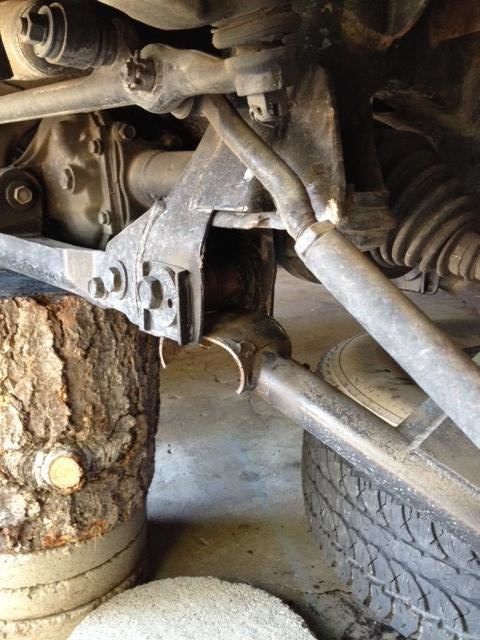
Back in October of 2013 a guy contacted me about some damage to his suspension on his Toyota Truck. He said the left hand LCA pulled apart during some mild offroading. He sent me the following photos. The first couple are from a few days before the truck went down.
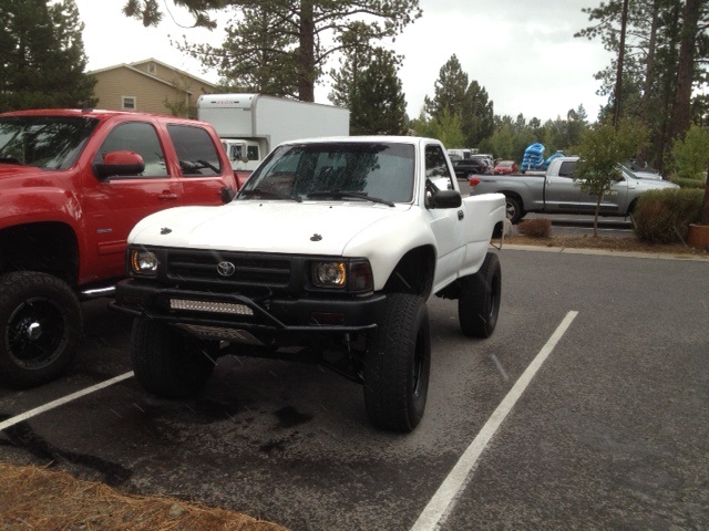
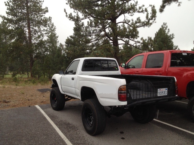
The next one is after it first broke. He said he had just driven over a small drainage swale in the trail. The suspension usually soaked up bumps much bigger than this with ease. For some reason this time it just collapsed.
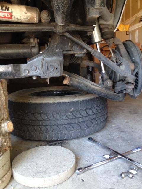
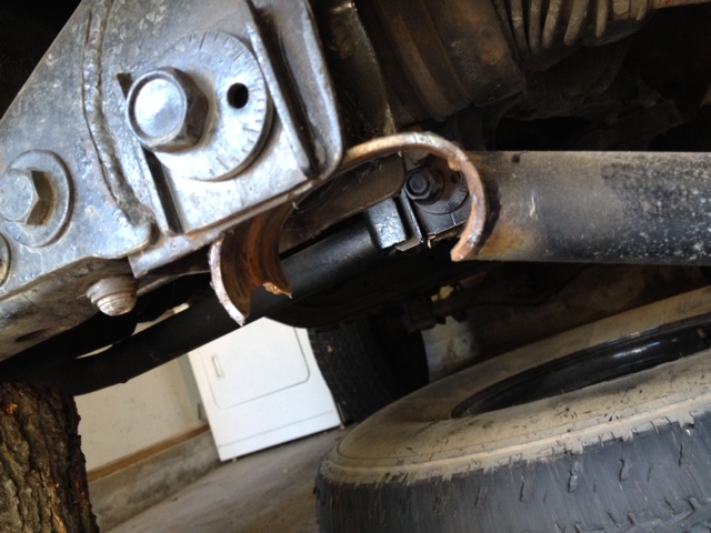
Here are a couple of close ups after he had it towed home and put on blocks.
He and I had a couple of e-mail chats and phone conversations discussing options. At first I suggested he find a fab shop to weld on a new end tube to just get it back on the road. This kit is a +2" over stock in control arm length so for me to build him a set of replacement +2" LCAs would take time. The other option was for him to purchase all new components and start over. He thought it over and ended up purchasing the Blazeland Long Arm kit and starting over. In the transaction I allowed him to use the damaged +2" UCAs /LCAs as core returns. I also offered to buy the rest of the components as I was wanting to examine the Porshe / Toyota CV axle assembly.
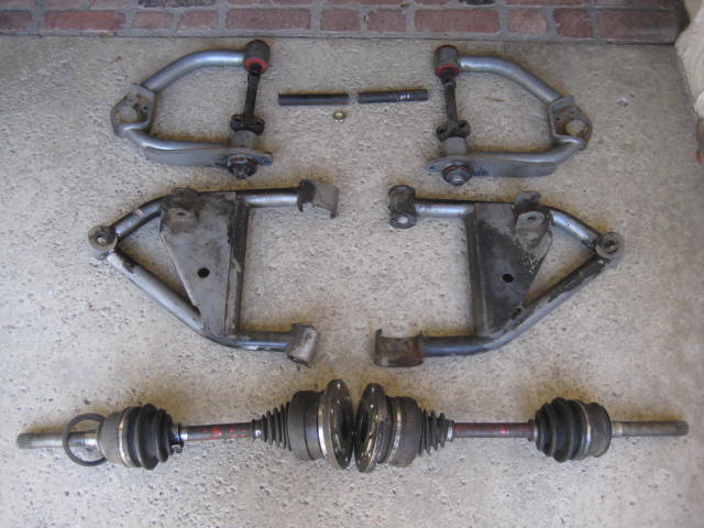
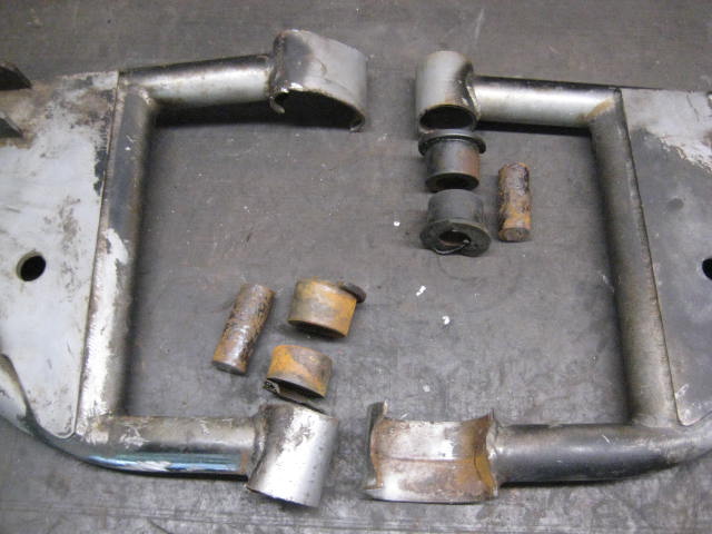
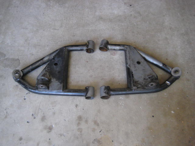
Anyway a few months went by and today I found a large box on my front doorstep. Here is a photo of the contents of the box.
I knew they guy who designed this kit, I knew the company who built and sold it. I also knew many of the problems with its design and poor service record. Many of you may also be able to identify the kit as well, but lets not go there. I am not posting this to bash on a failure to a group of people I knew and respected. I am posting this as an informational and educational read. There are lesson to be learned from things that fail. Yes, there were some design flaws, quality control issues, and general mistakes but there are also many good points. I find examining this kind of subject matter to be interesting and entertaining. I hope all who view this see it on that level.
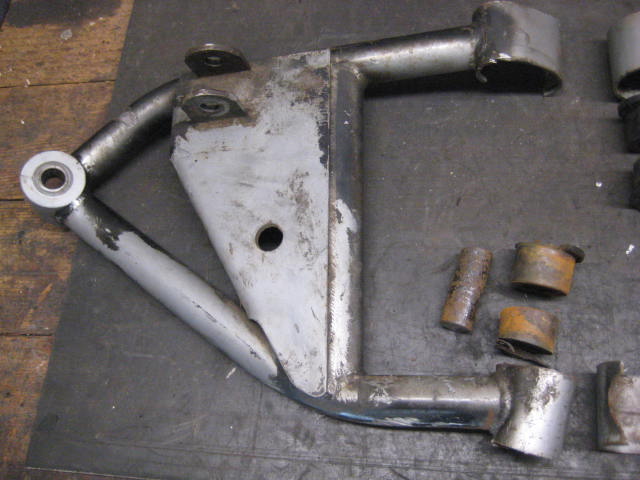
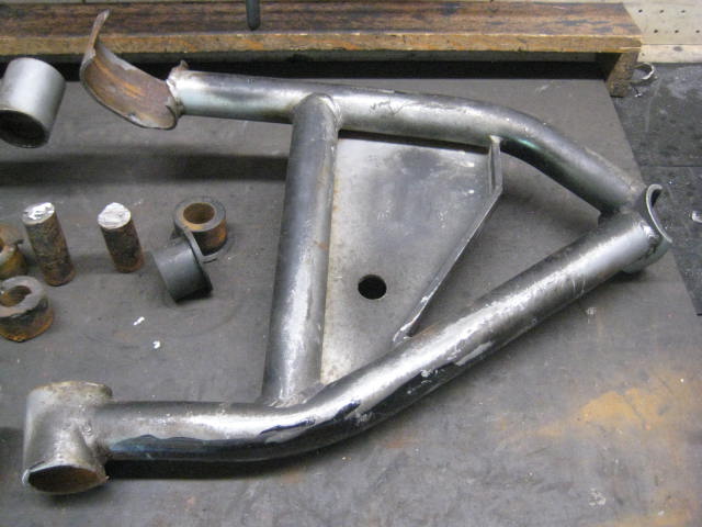
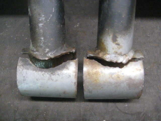
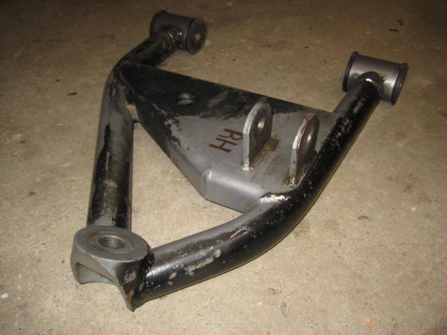
With that said I will start off with the obvious, the details of what took this kit out. Here are some close ups of the LCAs.
Left Hand top view
Right Hand top view
Right Hand bottom view
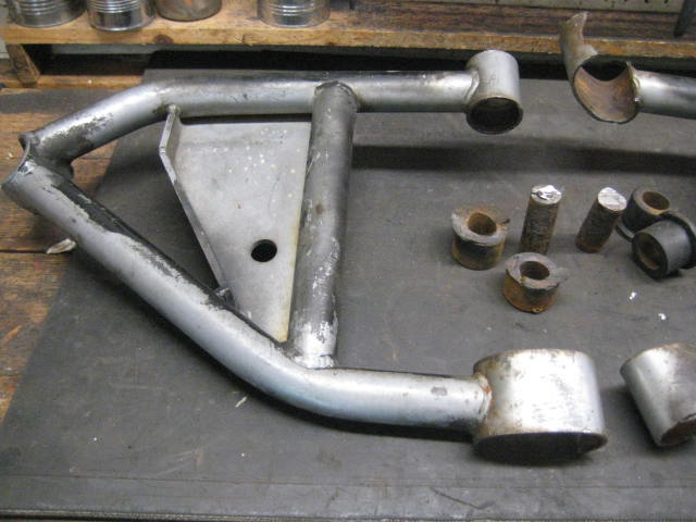
Left Hand bottom view
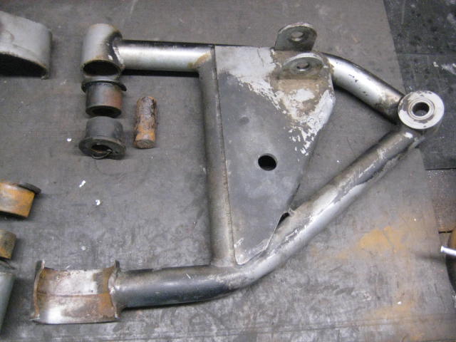
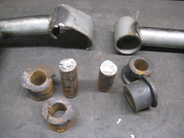
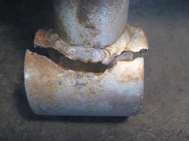
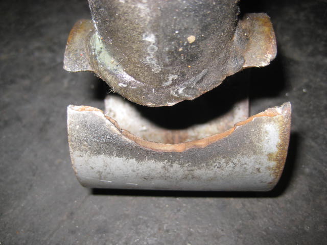
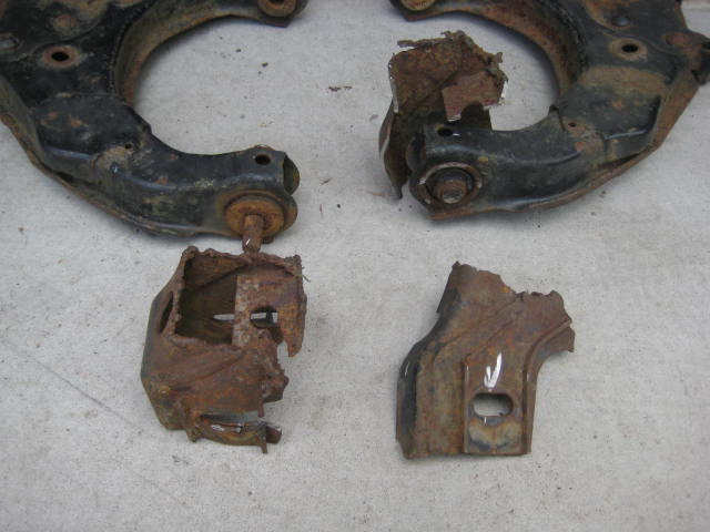
And here are some close ups of the bushings and such. Notice how thin wall the end tubes are. The wall thickness is .120 wall. You can see the tube failed along the weld seam. If the material is cromoly, my understanding is after welding it should be heat treated, maybe it wasn't? In one area the weld actually penetrates though the tube and weld protrudes into the inner diameter. That must have made pressing the bushing into place difficult.
Notice how rusty things are. The cam bolt and inner steel sleeve are seized together. To remove the LCA from the truck the cam bolt had to be cut out. I'd suspect the steel sleeve was bare metal and there was no sign of zinc plating. Maybe when hogging out the ID for a metric bolt it was done where as a rough surface with tooling marks resulted and that attracted the rust. Who knows if anti seize was ever applied during installation? Maybe the cam bolt was reused and was rusted all ready. After I disassembled the bushing assembly I put the sleeve and bolt on my anvil and tried to drive the bolt out with punch and 5lb sledge but I could get no movement.

I'd like to hear what you all think. If you have some comments or insights on what went wrong on this rig lets hear it. If you have examples of things that failed on the suspension of your IFS rig now is your turn to share.
The next one is after it first broke. He said he had just driven over a small drainage swale in the trail. The suspension usually soaked up bumps much bigger than this with ease. For some reason this time it just collapsed.
Here are a couple of close ups after he had it towed home and put on blocks.
He and I had a couple of e-mail chats and phone conversations discussing options. At first I suggested he find a fab shop to weld on a new end tube to just get it back on the road. This kit is a +2" over stock in control arm length so for me to build him a set of replacement +2" LCAs would take time. The other option was for him to purchase all new components and start over. He thought it over and ended up purchasing the Blazeland Long Arm kit and starting over. In the transaction I allowed him to use the damaged +2" UCAs /LCAs as core returns. I also offered to buy the rest of the components as I was wanting to examine the Porshe / Toyota CV axle assembly.
Anyway a few months went by and today I found a large box on my front doorstep. Here is a photo of the contents of the box.
I knew they guy who designed this kit, I knew the company who built and sold it. I also knew many of the problems with its design and poor service record. Many of you may also be able to identify the kit as well, but lets not go there. I am not posting this to bash on a failure to a group of people I knew and respected. I am posting this as an informational and educational read. There are lesson to be learned from things that fail. Yes, there were some design flaws, quality control issues, and general mistakes but there are also many good points. I find examining this kind of subject matter to be interesting and entertaining. I hope all who view this see it on that level.
With that said I will start off with the obvious, the details of what took this kit out. Here are some close ups of the LCAs.
Left Hand top view
Right Hand top view
Right Hand bottom view
Left Hand bottom view
And here are some close ups of the bushings and such. Notice how thin wall the end tubes are. The wall thickness is .120 wall. You can see the tube failed along the weld seam. If the material is cromoly, my understanding is after welding it should be heat treated, maybe it wasn't? In one area the weld actually penetrates though the tube and weld protrudes into the inner diameter. That must have made pressing the bushing into place difficult.
Notice how rusty things are. The cam bolt and inner steel sleeve are seized together. To remove the LCA from the truck the cam bolt had to be cut out. I'd suspect the steel sleeve was bare metal and there was no sign of zinc plating. Maybe when hogging out the ID for a metric bolt it was done where as a rough surface with tooling marks resulted and that attracted the rust. Who knows if anti seize was ever applied during installation? Maybe the cam bolt was reused and was rusted all ready. After I disassembled the bushing assembly I put the sleeve and bolt on my anvil and tried to drive the bolt out with punch and 5lb sledge but I could get no movement.
I'd like to hear what you all think. If you have some comments or insights on what went wrong on this rig lets hear it. If you have examples of things that failed on the suspension of your IFS rig now is your turn to share.
 04-02-2014, 03:19 AM
#2
Registered User
I think Engage offroad had a similar problem with their kit.
The answer was, if using a seamed pivot point, put the seam facing the tubular arm for support.

The answer was, if using a seamed pivot point, put the seam facing the tubular arm for support.
04-02-2014, 05:25 AM
#3
Registered User
Blaze, the cam bolt issue isn't isolated to this kit. I've seen many many trucks with siezed alignment cams, all of them on factory suspension systems. I can't begin to tell you what causes it.
As far as the rust inside of the bushing housing, the marks look as if they were staying stationary with the siezed cam bolt and sleeve, and turning within the tube itself.
As far as the rust inside of the bushing housing, the marks look as if they were staying stationary with the siezed cam bolt and sleeve, and turning within the tube itself.
04-02-2014, 08:53 AM
#5
Registered User
Thread Starter
Yeah I concur, the cam bolt / steel sleeve issue is common and the wear through the powdercoat on the ID / poly bushing means something was rubbing. I have had to cut a few cam bolts myself to get the LCAs off the truck. I have also had a few core returns come into my shop with seized bolts stuck in the bushing assembly. Sawzall blades can get up in there but dull out from the hardness of the material. Abrasive cut off wheels don't reach deep enough. I think the seize up is a result of the things I mention above along with age and environmental factors.
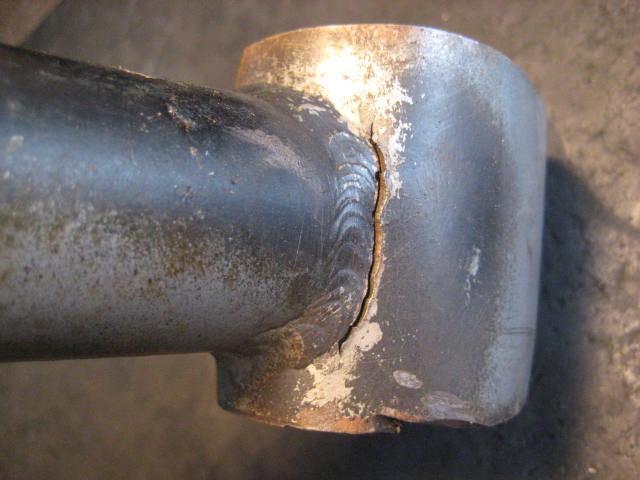
Hey Scuba, how goes it! I looked into it and found these control arms were made from chromoly (2" OD .120 wall at bushing tube shell). I did say the failure occurred at the weld seam and that was misleading. I didn't mean at the weld seam of the tube but the weld outline at the perpendicular intersection between tube to the shell. If you look closely at this picture you can see the failure path.
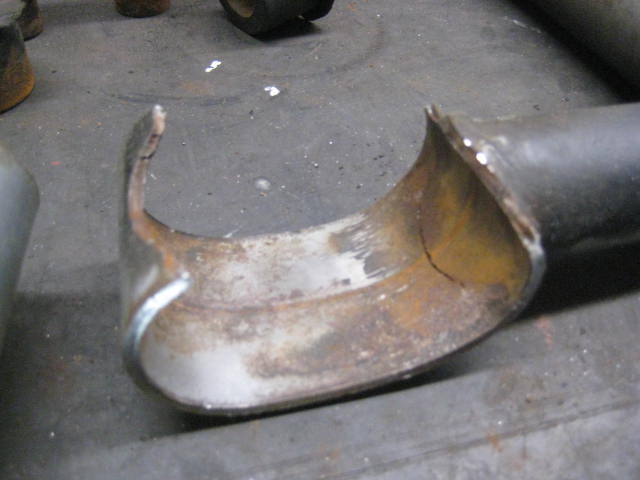
I did some brief research and reading and found there are a lot of factors involved with welding chromoly tube. Filler rod, heat treating, cleaning and prep., etc all effect the weld. When I look at the failure points I see cracking and brittleness within the material around the welds. My guess is something was done incorrectly in the welding process.
Hey Scuba, how goes it! I looked into it and found these control arms were made from chromoly (2" OD .120 wall at bushing tube shell). I did say the failure occurred at the weld seam and that was misleading. I didn't mean at the weld seam of the tube but the weld outline at the perpendicular intersection between tube to the shell. If you look closely at this picture you can see the failure path.
I did some brief research and reading and found there are a lot of factors involved with welding chromoly tube. Filler rod, heat treating, cleaning and prep., etc all effect the weld. When I look at the failure points I see cracking and brittleness within the material around the welds. My guess is something was done incorrectly in the welding process.
04-02-2014, 10:00 AM
#6
Registered User
Hey Scuba, how goes it! I looked into it and found these control arms were made from chromoly (2" OD .120 wall at bushing tube shell). I did say the failure occurred at the weld seam and that was misleading. I didn't mean at the weld seam of the tube but the weld outline at the perpendicular intersection between tube to the shell. If you look closely at this picture you can see the failure path.
I did some brief research and reading and found there are a lot of factors involved with welding chromoly tube. Filler rod, heat treating, cleaning and prep., etc all effect the weld. When I look at the failure points I see cracking and brittleness within the material around the welds. My guess is something was done incorrectly in the welding process.
04-02-2014, 04:00 PM
#7
Registered User
the weak point in a weld is usually on either side of the weld bead, unless you have a defective weld with porosity or lack of penetration for example.
does anyone know what thickness other kits normally use for bushing tube?
this serves as a reminder that you need to visually check your rig regularly.
thats why i liked to hand wash my racebikes, you can find things before they cause a problem sometimes.
does anyone know what thickness other kits normally use for bushing tube?
this serves as a reminder that you need to visually check your rig regularly.
thats why i liked to hand wash my racebikes, you can find things before they cause a problem sometimes.
Trending Topics
04-02-2014, 08:33 PM
#8
Registered User
Other side was about to go too, eh? Judging by the rusty edge of the break it looks like it could've been that way for a while, lucky it happened off road rather than on the highway!
I had some diff/crossmember drop brackets from trail Master crack, caught it before they caused trouble though. They were also about 1/8" thick. Gotta love those IFS lifts...
I had some diff/crossmember drop brackets from trail Master crack, caught it before they caused trouble though. They were also about 1/8" thick. Gotta love those IFS lifts...
04-03-2014, 09:55 AM
#9
Registered User
Thread Starter
I don't know what the story is on the other side? They just showed up like that! He never mentioned both sides being blown out. I asked about it when I was preparing the check to refund the core deposit and he said he only realized both sides were blown as he removed them from the truck. I also asked about the (3) missing Tie Rod Adjusting Sleeves jam nuts, which he replied are lost. So much for a complete, easily repairable kit. Never the less, I credited him the full $200 deposit in refund and bought the rest of the kit for $139.
Just so you guys know I really didn't want to press the issue and demand all the details. For all I know the truck was jumping at the Huck Fest when the LCAs failed. As I see it I made a sale, got a busted up set of control arms, and I bought a custom set of CVs. I say as a wash because I now have the kit to examine.
The inner CVs are Turbo Porsche units with custom machined adapter plate to mate with the Toyota differential stub flange. The axle shafts are custom machined 4130. If I were to R&D, design, and build all that it would be over $1K. Prototyping ain't cheap!
I'm not sure what I will end up doing with the kit. I could have my fabricator contacts repair the LCAs properly (and improve the failure points) then cobble together all the missing components and sell it? Before I do that I want to make sure I study it closely and get all I can from the design concept. The company who built it has been out of business for years so I doubt anyone cares what I do. It would be a shame to scrap all the embodied energy that went into making the system. However, I am primarily focusing on the CVs.
04-03-2014, 03:10 PM
#10
Registered User
Thread Starter
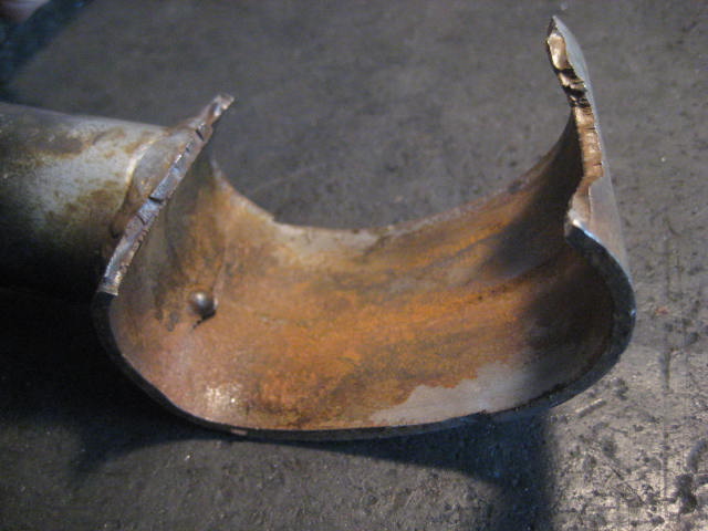
Here is a detail of the weld that penetrated completely through the tube wall into the I.D. It seems to me that when installing the bushings one would notice an obstruction like that?
Today I used a rubber mallet and hammered the bushing tube somewhat back into shape and took some better close up photos.
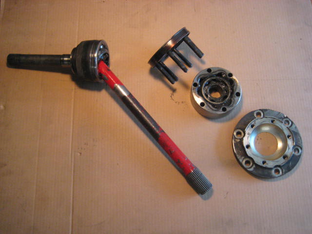
I also tore into the CV. It wasn't as complicated as I thought it might be. The adapter plate is a nice design. I can't figure out why there isn't some type of end cap between the adapter and the stub axle mounting flange. Seems like grease would find its way out. Maybe centrifugal forces spin it in a way that keeps it in place.
As for allowing more angle the Porsche design is better, however is it designed to run at extreme angles? As for plunge range the Toyota barrel / tripod design has more.
Today I used a rubber mallet and hammered the bushing tube somewhat back into shape and took some better close up photos.
I also tore into the CV. It wasn't as complicated as I thought it might be. The adapter plate is a nice design. I can't figure out why there isn't some type of end cap between the adapter and the stub axle mounting flange. Seems like grease would find its way out. Maybe centrifugal forces spin it in a way that keeps it in place.
As for allowing more angle the Porsche design is better, however is it designed to run at extreme angles? As for plunge range the Toyota barrel / tripod design has more.
 04-21-2014, 06:45 PM
#13
Registered User
Thread Starter
Hmmm, I doubt the owner knew that was coming up! The owner told me that after he put the Blazeland kit on the truck he sold it to a friend. I'll have to send him an Email and get an update on the rig. It is a really nice rig, I thought about buying it but I am too tall and big for a standard cab.
04-25-2014, 02:39 PM
#14
Registered User
Thread Starter
Here is a set of LCA cores a customer sent me. The cam bolts was so seized up, he torch cut the frame apart to get them off. The donor rig was being parted out and scrapped. When I process these arms they will undergo a burn recovery and a sandblast. The bushing rubber burns away and the LCA shell, the inner steal sleeves, and the captured steel washers come out clean and ready for fresh zinc plate.
Last edited by BlazeN8; 04-25-2014 at 02:41 PM.
01-05-2015, 08:36 PM
#16
Registered User
Thread Starter
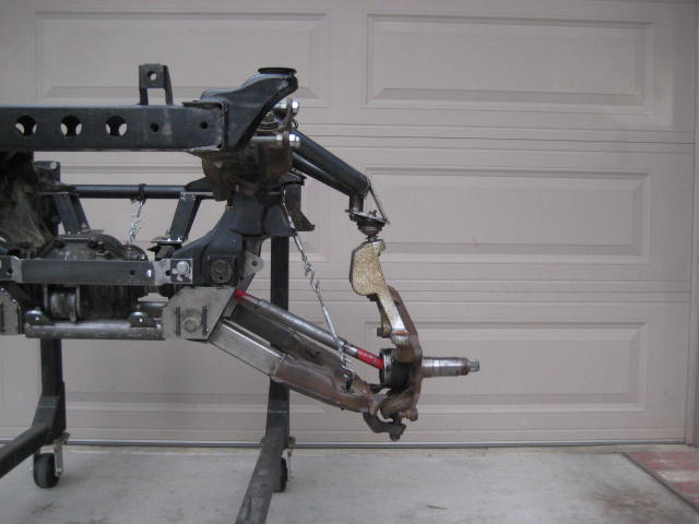
Update on this thread. I did a quick repair on one of the LCAs. I tack welded a new tube eye into place and installed a pair of new bushings.
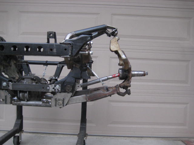
I then installed the kit on my mock up frame section.
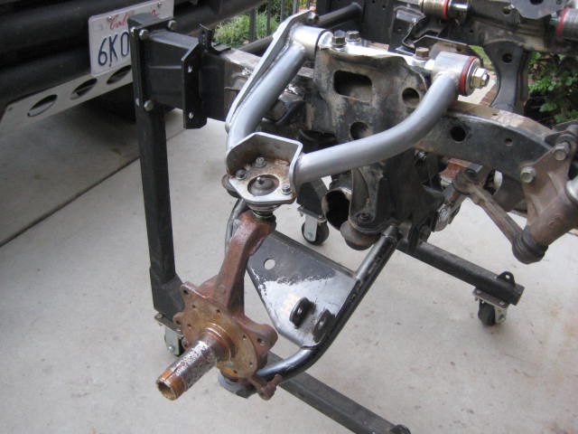
I attempted to cycled the suspension but the UCA bushings wouldn't rotate. I removed the UCAs and took them over to the work bench and jaw vise. I pressed out the bushings, which were extremely dry and difficult to remove. Once I got them out I found the steel tube, which formed the pivot eye, was deformed and oval shaped. Again .120 wall tube. It was built from 2" O.D. There was little chance of me being able to grease up the bushings and pressing them back in to achieve rotation so I almost scrapped my efforts. Then I remembered my local exhaust shop had a machine to flare exhaust pipe. I wasn't sure .120 cromoly tube could be flared but the machine handled it no problem. Now that the tube was round again I figured I was back in business, but I wasn't.
I re-greased the bushings and pressed them back into UCA and onto the cross shaft. Then I went to tighten the hardware and found the assembly didn't fit together correctly. The bushing, the tube, and the cross shaft all had different lengths so as the nut was tightened it compressed the bushing and locked up any chance of rotation. The nut only engaged a few threads. The nut was not a top lock or a nylock and there was no crown to stake over like a factory nut. I had no way of getting the nut seated on the chamfer of the cross shaft without crushing the bushing length about 1/2", talk about bushing pre-load! The washer was an off the shelf washer probably 3/4 size. It didn't fit the cross shaft or the bushing.
For the time being I decided to not install the washer or nuts and just leave everything loose so that it would rotate. I was now able cycled the suspension. I took some measurements. With Bump and Droop stops installed I got 8-7/8" travel. With Bump and Droop stops removed (metal to metal) I got 11-7/8" travel. There was some binding in the ball joints during the metal to metal cycle so I adjusted until no binding and attained a usable measurement of 10 1/2" travel.
I didn't connect the steering linkage or install the CVs so I cannot say for sure that 10 1/2" was the actual usable number but at least I have a good idea of what a +2" over stock design can offer.
The LCA bushings and tube was bad enough but the UCA bushing problems are the last straw, this set of arms is not salvageable. I can't see how it held together as long as it did? Right out of the box brand new I would be afraid to drive down the driveway!
In the following photo I placed the factory cross shaft in the middle and to the left all the components of a factory UCA. On the right all the components of the aftermarket UCA. I am so disappointed!
I then installed the kit on my mock up frame section.
I attempted to cycled the suspension but the UCA bushings wouldn't rotate. I removed the UCAs and took them over to the work bench and jaw vise. I pressed out the bushings, which were extremely dry and difficult to remove. Once I got them out I found the steel tube, which formed the pivot eye, was deformed and oval shaped. Again .120 wall tube. It was built from 2" O.D. There was little chance of me being able to grease up the bushings and pressing them back in to achieve rotation so I almost scrapped my efforts. Then I remembered my local exhaust shop had a machine to flare exhaust pipe. I wasn't sure .120 cromoly tube could be flared but the machine handled it no problem. Now that the tube was round again I figured I was back in business, but I wasn't.
I re-greased the bushings and pressed them back into UCA and onto the cross shaft. Then I went to tighten the hardware and found the assembly didn't fit together correctly. The bushing, the tube, and the cross shaft all had different lengths so as the nut was tightened it compressed the bushing and locked up any chance of rotation. The nut only engaged a few threads. The nut was not a top lock or a nylock and there was no crown to stake over like a factory nut. I had no way of getting the nut seated on the chamfer of the cross shaft without crushing the bushing length about 1/2", talk about bushing pre-load! The washer was an off the shelf washer probably 3/4 size. It didn't fit the cross shaft or the bushing.
For the time being I decided to not install the washer or nuts and just leave everything loose so that it would rotate. I was now able cycled the suspension. I took some measurements. With Bump and Droop stops installed I got 8-7/8" travel. With Bump and Droop stops removed (metal to metal) I got 11-7/8" travel. There was some binding in the ball joints during the metal to metal cycle so I adjusted until no binding and attained a usable measurement of 10 1/2" travel.
I didn't connect the steering linkage or install the CVs so I cannot say for sure that 10 1/2" was the actual usable number but at least I have a good idea of what a +2" over stock design can offer.
The LCA bushings and tube was bad enough but the UCA bushing problems are the last straw, this set of arms is not salvageable. I can't see how it held together as long as it did? Right out of the box brand new I would be afraid to drive down the driveway!
In the following photo I placed the factory cross shaft in the middle and to the left all the components of a factory UCA. On the right all the components of the aftermarket UCA. I am so disappointed!
01-07-2015, 06:44 PM
#17
Registered User
Thread Starter
Today I had a couple of hours to mess around with the CV Axles. Knowing that I am never going to use the +2" Long Travel kit because of the bushing issues and because +2" just doesn't get much more than 10-1/2" of travel I decided to cut the center bar of one of the CVs and lengthen it to fit into a sample design I am playing around with.
The lengthened axle center bar for this mock up is approximately +6" over stock. The only real difference between the factory CV assembly and the VW hybrid assembly (red paint) is the inner joint barrel.
The lengthened axle center bar for this mock up is approximately +6" over stock. The only real difference between the factory CV assembly and the VW hybrid assembly (red paint) is the inner joint barrel.
01-07-2015, 06:45 PM
#18
Registered User
Thread Starter
I then plugged the two assemblies into the mock up and cycled the suspension.
The stock CV assembly will handle 14.250" of travel and the hybrid will handle 14.625"
of travel. The geometry of the control arm mock up without CVs is about 15" The ball joints and steering linkage is the limiting factor with CVs removed from the equation.
The stock CV assembly binds at droop with the center bar hitting the barrel tripod. At full stuff the tripod moves to the outer limits of the barrel, the plunge is extended nearly to the limit. There is more plunge to play with by lengthening the center bar and letting it go deeper but the angle at droop is the real limiting factor, and a longer center bar will bind sooner as it rides deeper in the barrel. It may be possible to clearance the barrel to get a bit more but that means custom machining.
The VW hybrid center bar is slightly longer as the axle rides deeper into the plunge. The plunge of the VW is about half of a stock unit. At full stuff the joint operates comfortably. At droop the VW joint is just about maxed out, as is the outer factory joint.
Between the two joints I am seeing an additional .375 or 3/8" in droop with the VW. To me that amount of gain in not worth the added effort and expense. If the VW hybrid would allow all 15" of travel it may be worth pursuing but even then the outer joint becomes the issue.
Another disappointment to the +2" design, I was hoping the VW hybrid would amaze me with spectacular numbers but the reality is its a fizzle.


