
 04-05-2016, 09:22 AM
Last edit by: IB Advertising
See related guides and technical advice from our community experts:
- Toyota Tundra How to Replace Timing Belt and Water Pump<br>Step by step instructions for do-it-yourself repairs.

Tundra 4.7 (2uz) Timing Belt & Water Pump Replacement
01-25-2010, 08:32 AM
#21
Registered User
Thread Starter
http://cgi.ebay.com/ebaymotors/99-07...Q5fAccessories
If that link doesn't work, it is a seller named "volkstoy" you can narrow the search that way.
 02-20-2010, 06:52 PM
#22
Registered User
Timing belts are quiet, light and accurate but a major service headache for OHC engines. I therefore avoid vehicles with timing belts.
Does the new '10 4.6L have the same belt?
Does the new '10 4.6L have the same belt?
03-01-2010, 03:46 PM
#23
Registered User

Join Date: Jan 2010
Posts: 1
Likes: 0
Received 0 Likes
on
0 Posts
I cannot thank you enought for this post! it helped me decide to do my t belt and water pump job myself on my 05 Sequoia. It went rather well with this write up along with a manual. I have done t belts before on other models but was kind of nervous about this one. Mine also has the VVTI which made no difference if anyone else was wondering about it, it is the same there are no differences in timing it or anything, which is what i was worried about. But again thanks a million for this great post it was very helpfull.
03-17-2010, 12:51 PM
#24
Registered User
Thread Starter
I cannot thank you enought for this post! it helped me decide to do my t belt and water pump job myself on my 05 Sequoia. It went rather well with this write up along with a manual. I have done t belts before on other models but was kind of nervous about this one. Mine also has the VVTI which made no difference if anyone else was wondering about it, it is the same there are no differences in timing it or anything, which is what i was worried about. But again thanks a million for this great post it was very helpfull.
I'm glad that you found this thread useful. Thanks for the info on the VVTI too.
10-26-2010, 08:42 AM
#26
Registered User

Join Date: Sep 2010
Posts: 2
Likes: 0
Received 0 Likes
on
0 Posts
All of these photos are from my 2004 Sequoia with 106K on the odo. We did have a fan clutch give up at about the 75-85K mark, but other than that, no real problems with this vehicle what-so-ever. Wish it had more HP, but for the reliability we have had, I can live with it.
I was in the same boat with my water pump only showed signs of leakage at the weep hole on the back of the water pump. Before I removed it I only noticed a red/white-ish trail off of the bottom closest to the A/C compressor, look closely to his photo and you will see it too. Once I removed the pump I could clearly see it had been leaking from the weep hole, only visible from the back of the pump after removal.
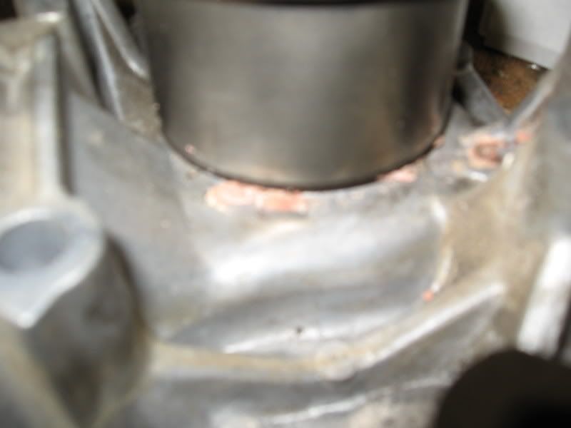
When I got my belt and pulley off, I noticed a couple of things. First, the belt looked like it was still in fairly decent shape, with no obvious areas of concern. I know some people have tempted fate and ran them for many miles over what I did. My w/p was a different story. I could see some pink concretions under the pulley and at the weep hole that were caused by coolant leakage. Slight leakage, but leakage non-the-less. This crumby picture shows what I am talking about, sorry it it so blurry:
I imagine that if I had neglected to do this preventative maintenance, the water pump would have sprung a serious leak sometime in the near future. I'm sure it would have failed and required teardown before the timing belt broke anyway, if I had not performed this repair. If I had decided to just do the t-belt and not mess with the w/p, I would have been tearing it all apart again to replace the w/p. obviously, this is why it is best to get it all in one shot, and the extra expense is worth it. I got lazy and elected not to replace the crankshaft and camshaft seals. They were completely leak free, so I decided to let sleeping dogs lie. I hope it doesn't come back to bite me!
Next I cleaned the gasket surface and installed the w/p and gasket with black RTV. Then I installed the new idler and tensioner pulleys. Now for the belt.
I mentioned earlier that I have replaced t-belts on a number of different makes and models. Many of them have little tricks and techniques to get everything all set up correctly, and this one is no different. I recommend reading and re-reading your manual before you start setting up the cam timing because it is a critical step.
It is easiest to do this if you have an extra arm extending from the center of your chest, but if not, a friend can help you hold the t-belt while you get it all lined up and indexed. The process on this engine goes as follows:
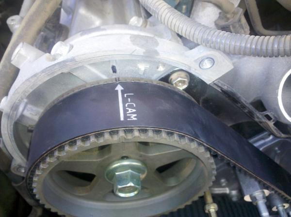
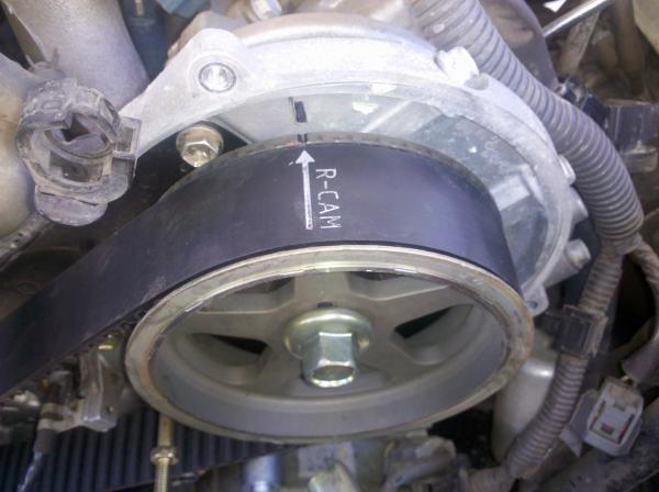
The new timing belt should have marks on it that correspond to the marks on the cam sprockets and the crank sprocket. The references are from sitting in the drivers seat, so they are reversed from the way you are looking at it and that can get confusing. Make sure that the crank is at TDC by referencing a groove on the upper side of the crank sprocket and a raised dimple on the oil pump housing( I regretfully didn't get a good pic of that mark, but you will see it and understand immediately). Start by positioning the left cam sprocket (on your right side) at the "T" position and then install the belt so the line on the belt matches up with the line on the sprocket. Have a helper hold the belt on the cam sprocket so it does not move, then route the belt onto the crank sprocket so that the line on the belt is in line with the dot on the lower side (this is not the crank TDC reference I mentioned above. It is a separate mark which can be seen on the lower side front of the crank sprocket). Only those two sprockets are engaged with the belt at this point. Now you need to use a 17mm wrench on the cam sprocket and gently rotate the mark on the sprocket so it lines up with the straight line on the backing plate. That will take up all the slack in the belt between the cam sprocket and the crank sprocket. You can now position the right side (again, it is on your left) cam sprocket on the "T" mark and finish routing the t-belt onto it and around the tensioner and idler. Make sure the line on the belt is lined up with the mark on the sprocket, then gently rotate the cam sprocket so that the mark on it lines up with the straight line on the backing plate. That will put tension on the belt between the two cam sprockets and conveniently put all the slack on the side of the belt adjacent to the tensioner.
A few words about the tensioner. When I removed mine, I tested it by trying to push the now extended rod back into the body by holding it against my bench vise and leaning my body weight against it. It didn't budge and therefore appeared to be satisfactory. Then I had to get it ready to reinstall. I forgot to get pics of this process as well, but it is in the manual. I placed the tensioner in my vice so that when I turned the handle it would compress the shaft into the body. There is a hole in the shaft that lines up with a hole in the tensioner body when compressed. I inserted a small nail in the hole to hold the shaft in the body until assembly. I then bolted the tensioner onto the bracket and pulled the nail out which allows the tensioner to apply tension to the belt. It looked like this when I was all done. The tensioner is barely seen on the bottom left of the photo. The shaft pushes straight up on the tensioner pulley assenbly.
I was able to get a few photos you missed, hope this helps everyone. Also there were a few small items your AWESOME (seriously thanks for putting all that together) description of the task that were missing. I will cover them below.
1. I didn't remove the radiator or any of the big stuff the FSM recommends doing. I left the A/C compressor in place and only removed the fwd 2 bolts holding to the spider mount that holds the bearing for the rad fan.
2. I was able to capture 90% of my coolant, used a paint type paper filter/funnel and reused it. Drain the radiator the petcock, on the aft left of the radiator (ALL DESCRIPTIONS ARE GIVEN "IN CAR POSITION" AS IF YOU WERE SITTING IN THE DRIVERS SEAT) then remove the spring clamp to the top of the radiator, position it up stream of the on the radiator hose, once the coolant has drained enough for you to remove that same upper hose from the head cross over pipe, without loosing more coolant remove it. Next remove the hose to the thermostat housing, if the coolant looks like it will come out give it a second and let the radiator keep draining. I cant remember if there were other things to remove, but the next step for draining and catching all/most of the coolant was to remove the spring clamp from the coolant line that goes to the throttle body then the thermostat housing. Then unbolt the two 10mm bolts holding that stainless hardline to the front of the motor. Your coolant should be done draining by now from the rad petcock, close it and move the bucket to the passenger side kind of under the alternator, leaving that bottom hose attached to the oil cooler assembly, bend at the rubber hose to the passenger side and the bucket should be in close to the correct place to catch the rest of the coolant that comes out. Once you get to removing the water pump you will get a little more coming out of the pump put the bucket in the center L/R and center it fore and aft under the crossmember and you should catch the rest as it drains a littl over the front and a little ove the back.
3. Now I see in your photos that it looks like you didn't remove the power steering pump top stud. I did, and now see that it wasn't necessary, doing that just made reinstalling the stud difficult, and a tad time consuming. Just remove the other 2 pwr steering bolts and loosen that top nut and rotate it to the side to remove the alternator.
4. When reinstalling everything I forgot to put that bolt in right above the alt that holds the tensioner saddle bracket on. It would be the bottom right bolt on that bracket. I just didn't notice it, till I was almost done and there was only that bolt left in my tray.
5. And most important and very easy. The best way to find TDC compression, (remember there is TDC compression and TDC exhaust, and since this is TIMING we need TDC compression) is to rotate the crank with a breaker bar to 0 (zero) on the little white timing mark on the crank pulley (harmonic damper) and (after the covers are removed) look at the lines on the cam spokes, if they dont line up with the marks on back plate, then you need to do another 360deg with the crank. Then all the marks should line up like this. I didn't look at the book or anything for the timing, I have done almost 100 timing/engine assemblies, so I wasn't too worried about it. I have had motors, were once the cam belt/chain were removed the cam would rotate a bit because the cam lobes pushed it one way or another, but that was not the case here.
6. In your photos, it looks like you had a felt, paper type water pump gasket. I got a Toyota pump and it came with the factory pump gasket, and an extra bolt (maybe another model uses that bolt) and it is a SUPER high quality stainless steel 3 layer, with an awesome integrated/bonded seal on the sealing edge, the original one came apart but hadn't shown any signs of leaking. So even if you dont use the original pump, make sure to use the OEM gasket, its very nice.
7. The only parts needed if you are definitely replacing the water pump and the tensioner/idler are
1. Timing belt
2. Tensioner bearing
3. Idler Bearing
4. Water pump
5. small o-ring (going to back of water pump, on stainless tube)
6. big o-ring (going to thermostat housing)
7. Sealant (RTV or FIPG from Toyota, that stuff really is WAY better than regular Permatex RTV)
Here are a few more photos, that might help.
Timing mark on right cam pulley, also notice one of the 5 spokes on that pulley/wheel has a long line on it to help you find the mark if its facing down. Once you break the 22mm bolt on the crank loose you should be able to grab the harmonic damper with your hands and rotate it back to TDC compression. For removal and installation of that 22mm bolt, I held the outside lip of the harmonic damper still with a HUGE set of channel locks (make sure you know which way to install channel locks if you do this) it would be nice to have a friend help with this but its not required if you have the muscle, I used a 1ft extension on my 2ft breaker bar for removal, worked easily.
Timing mark on left cam pulley
Timing mark on bottom
Pressing tensioner back in

The FSM says to use a 1.5 mm allen wrench to fit through the holes, but a 2mm fit fine.

Fortunately all the water pump bolts are the same length, but the 2 bolts that hold the the tensioner in have an unthreaded portion of the grip length. Make sure not to mix these up.

Here you can (barely) see the small tube that you will need the small o-ring for, where it goes into the back of the water pump.

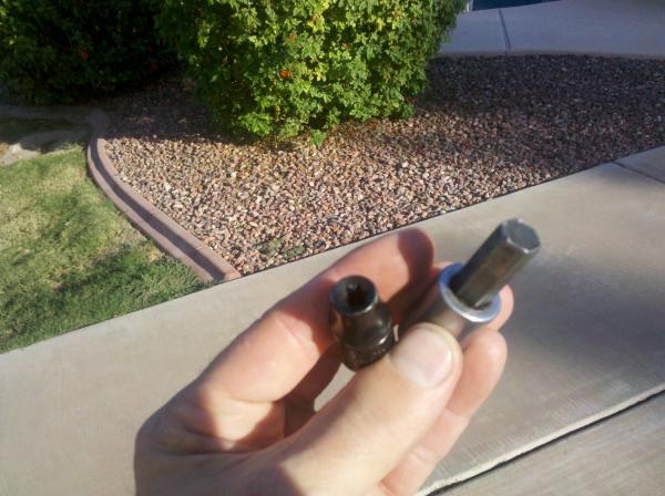
Here are the only 2 specialty tools you will need for this job, Oh and a big set of needle nose pliers to remove those spring style hose clamps. Heck, you might not even need that special female torx socket if you dont want to remove that top stud that holds the power steering pump. The other is a 10mm Allen, for removing the tensioner pivot.
Don't forget this!!! This is the crank position sensor ring, the motor wont run without it. Oddly enough, this is the only motor I have ever worked on where the key-way wasn't at TDC on the motor when the crank was at TDC.

Also, I had to bend this little bracket that shields the wires going to the A/C compressor. It kept me from getting that spider bracket fitting that holds the bearing for the radiator fan and fan clutch. It bent right back easily.

I was in the same boat with my water pump only showed signs of leakage at the weep hole on the back of the water pump. Before I removed it I only noticed a red/white-ish trail off of the bottom closest to the A/C compressor, look closely to his photo and you will see it too. Once I removed the pump I could clearly see it had been leaking from the weep hole, only visible from the back of the pump after removal.
When I got my belt and pulley off, I noticed a couple of things. First, the belt looked like it was still in fairly decent shape, with no obvious areas of concern. I know some people have tempted fate and ran them for many miles over what I did. My w/p was a different story. I could see some pink concretions under the pulley and at the weep hole that were caused by coolant leakage. Slight leakage, but leakage non-the-less. This crumby picture shows what I am talking about, sorry it it so blurry:
I imagine that if I had neglected to do this preventative maintenance, the water pump would have sprung a serious leak sometime in the near future. I'm sure it would have failed and required teardown before the timing belt broke anyway, if I had not performed this repair. If I had decided to just do the t-belt and not mess with the w/p, I would have been tearing it all apart again to replace the w/p. obviously, this is why it is best to get it all in one shot, and the extra expense is worth it. I got lazy and elected not to replace the crankshaft and camshaft seals. They were completely leak free, so I decided to let sleeping dogs lie. I hope it doesn't come back to bite me!
Next I cleaned the gasket surface and installed the w/p and gasket with black RTV. Then I installed the new idler and tensioner pulleys. Now for the belt.
I mentioned earlier that I have replaced t-belts on a number of different makes and models. Many of them have little tricks and techniques to get everything all set up correctly, and this one is no different. I recommend reading and re-reading your manual before you start setting up the cam timing because it is a critical step.
It is easiest to do this if you have an extra arm extending from the center of your chest, but if not, a friend can help you hold the t-belt while you get it all lined up and indexed. The process on this engine goes as follows:
The new timing belt should have marks on it that correspond to the marks on the cam sprockets and the crank sprocket. The references are from sitting in the drivers seat, so they are reversed from the way you are looking at it and that can get confusing. Make sure that the crank is at TDC by referencing a groove on the upper side of the crank sprocket and a raised dimple on the oil pump housing( I regretfully didn't get a good pic of that mark, but you will see it and understand immediately). Start by positioning the left cam sprocket (on your right side) at the "T" position and then install the belt so the line on the belt matches up with the line on the sprocket. Have a helper hold the belt on the cam sprocket so it does not move, then route the belt onto the crank sprocket so that the line on the belt is in line with the dot on the lower side (this is not the crank TDC reference I mentioned above. It is a separate mark which can be seen on the lower side front of the crank sprocket). Only those two sprockets are engaged with the belt at this point. Now you need to use a 17mm wrench on the cam sprocket and gently rotate the mark on the sprocket so it lines up with the straight line on the backing plate. That will take up all the slack in the belt between the cam sprocket and the crank sprocket. You can now position the right side (again, it is on your left) cam sprocket on the "T" mark and finish routing the t-belt onto it and around the tensioner and idler. Make sure the line on the belt is lined up with the mark on the sprocket, then gently rotate the cam sprocket so that the mark on it lines up with the straight line on the backing plate. That will put tension on the belt between the two cam sprockets and conveniently put all the slack on the side of the belt adjacent to the tensioner.
A few words about the tensioner. When I removed mine, I tested it by trying to push the now extended rod back into the body by holding it against my bench vise and leaning my body weight against it. It didn't budge and therefore appeared to be satisfactory. Then I had to get it ready to reinstall. I forgot to get pics of this process as well, but it is in the manual. I placed the tensioner in my vice so that when I turned the handle it would compress the shaft into the body. There is a hole in the shaft that lines up with a hole in the tensioner body when compressed. I inserted a small nail in the hole to hold the shaft in the body until assembly. I then bolted the tensioner onto the bracket and pulled the nail out which allows the tensioner to apply tension to the belt. It looked like this when I was all done. The tensioner is barely seen on the bottom left of the photo. The shaft pushes straight up on the tensioner pulley assenbly.
1. I didn't remove the radiator or any of the big stuff the FSM recommends doing. I left the A/C compressor in place and only removed the fwd 2 bolts holding to the spider mount that holds the bearing for the rad fan.
2. I was able to capture 90% of my coolant, used a paint type paper filter/funnel and reused it. Drain the radiator the petcock, on the aft left of the radiator (ALL DESCRIPTIONS ARE GIVEN "IN CAR POSITION" AS IF YOU WERE SITTING IN THE DRIVERS SEAT) then remove the spring clamp to the top of the radiator, position it up stream of the on the radiator hose, once the coolant has drained enough for you to remove that same upper hose from the head cross over pipe, without loosing more coolant remove it. Next remove the hose to the thermostat housing, if the coolant looks like it will come out give it a second and let the radiator keep draining. I cant remember if there were other things to remove, but the next step for draining and catching all/most of the coolant was to remove the spring clamp from the coolant line that goes to the throttle body then the thermostat housing. Then unbolt the two 10mm bolts holding that stainless hardline to the front of the motor. Your coolant should be done draining by now from the rad petcock, close it and move the bucket to the passenger side kind of under the alternator, leaving that bottom hose attached to the oil cooler assembly, bend at the rubber hose to the passenger side and the bucket should be in close to the correct place to catch the rest of the coolant that comes out. Once you get to removing the water pump you will get a little more coming out of the pump put the bucket in the center L/R and center it fore and aft under the crossmember and you should catch the rest as it drains a littl over the front and a little ove the back.
3. Now I see in your photos that it looks like you didn't remove the power steering pump top stud. I did, and now see that it wasn't necessary, doing that just made reinstalling the stud difficult, and a tad time consuming. Just remove the other 2 pwr steering bolts and loosen that top nut and rotate it to the side to remove the alternator.
4. When reinstalling everything I forgot to put that bolt in right above the alt that holds the tensioner saddle bracket on. It would be the bottom right bolt on that bracket. I just didn't notice it, till I was almost done and there was only that bolt left in my tray.
5. And most important and very easy. The best way to find TDC compression, (remember there is TDC compression and TDC exhaust, and since this is TIMING we need TDC compression) is to rotate the crank with a breaker bar to 0 (zero) on the little white timing mark on the crank pulley (harmonic damper) and (after the covers are removed) look at the lines on the cam spokes, if they dont line up with the marks on back plate, then you need to do another 360deg with the crank. Then all the marks should line up like this. I didn't look at the book or anything for the timing, I have done almost 100 timing/engine assemblies, so I wasn't too worried about it. I have had motors, were once the cam belt/chain were removed the cam would rotate a bit because the cam lobes pushed it one way or another, but that was not the case here.
6. In your photos, it looks like you had a felt, paper type water pump gasket. I got a Toyota pump and it came with the factory pump gasket, and an extra bolt (maybe another model uses that bolt) and it is a SUPER high quality stainless steel 3 layer, with an awesome integrated/bonded seal on the sealing edge, the original one came apart but hadn't shown any signs of leaking. So even if you dont use the original pump, make sure to use the OEM gasket, its very nice.
7. The only parts needed if you are definitely replacing the water pump and the tensioner/idler are
1. Timing belt
2. Tensioner bearing
3. Idler Bearing
4. Water pump
5. small o-ring (going to back of water pump, on stainless tube)
6. big o-ring (going to thermostat housing)
7. Sealant (RTV or FIPG from Toyota, that stuff really is WAY better than regular Permatex RTV)
Here are a few more photos, that might help.
Timing mark on right cam pulley, also notice one of the 5 spokes on that pulley/wheel has a long line on it to help you find the mark if its facing down. Once you break the 22mm bolt on the crank loose you should be able to grab the harmonic damper with your hands and rotate it back to TDC compression. For removal and installation of that 22mm bolt, I held the outside lip of the harmonic damper still with a HUGE set of channel locks (make sure you know which way to install channel locks if you do this) it would be nice to have a friend help with this but its not required if you have the muscle, I used a 1ft extension on my 2ft breaker bar for removal, worked easily.
Timing mark on left cam pulley
Timing mark on bottom
Pressing tensioner back in
The FSM says to use a 1.5 mm allen wrench to fit through the holes, but a 2mm fit fine.
Fortunately all the water pump bolts are the same length, but the 2 bolts that hold the the tensioner in have an unthreaded portion of the grip length. Make sure not to mix these up.
Here you can (barely) see the small tube that you will need the small o-ring for, where it goes into the back of the water pump.
Here are the only 2 specialty tools you will need for this job, Oh and a big set of needle nose pliers to remove those spring style hose clamps. Heck, you might not even need that special female torx socket if you dont want to remove that top stud that holds the power steering pump. The other is a 10mm Allen, for removing the tensioner pivot.
Don't forget this!!! This is the crank position sensor ring, the motor wont run without it. Oddly enough, this is the only motor I have ever worked on where the key-way wasn't at TDC on the motor when the crank was at TDC.
Also, I had to bend this little bracket that shields the wires going to the A/C compressor. It kept me from getting that spider bracket fitting that holds the bearing for the radiator fan and fan clutch. It bent right back easily.
Last edited by ARZ; 10-26-2010 at 08:52 AM.
11-11-2010, 03:54 PM
#27
Registered User

Join Date: Nov 2010
Posts: 2
Likes: 0
Received 0 Likes
on
0 Posts
Great DIY! I also used this to help me along the way. Here is my write up. Maybe it adds a little something to the mix. My only issues were the fan clutch removal and fan bracket.
http://m3pink.blogspot.com/2010/11/c...uiser-2uz.html
Also, I believe the pictures above show the timing belt installed backwards. It is most likely symmetrical and doesn't matter, but the left cam is the left cam on the driver's side. The arrow on the crank will point at the white circle that way and the Toyota SM refer to right and left as if you were driving. Also it looks like the crank is off one notch in that image.
Any comments or crits on my writeup are welcome as well.
Last edited by pink; 11-11-2010 at 03:55 PM.
11-14-2010, 01:30 PM
#28
Registered User
Join Date: Sep 2010
Posts: 2
Likes: 0
Received 0 Likes
on
0 Posts
Heck yea, I think you might me right about me putting the belt on backwards, but I am 100% confident the cams and the crank did not move, so I think the timing is correct. I didn't notice that little dot on the crank pulley till you pointed it out just now. I think if the belt gets installed backwards like mine is, (appears to be) that indication point on the belt for the crank ends up being a tooth off. I don't think the timing is off as the power feels EXACTLY the same and we just put 800+ miles on it in a trip from Phx to LA, and we got 17 mpg going 85mph. A trick I use for removing fan clutches with 4 bolts like this is to get two 12mm wrenches, position the one that will be tightening a bolt so that it can only rotate a tiny bit before it pinches against the center shaft/flange of the flan clutch housing, then you can loosen the other 3 bolts. Once 3 are loose, (just a tiny bit loose) put the tightening wrench on one of those 3 and repeat to loosen the 4th one. I took about 6 hours wrench time, so I guess my rushing might have contributed to the backwards belt. I remember thinking that the lower mark didnt seem to confidence inspiring (since I didnt notice that little divet mark on the crank. Shame-on-me since I KNEW all the FSM always referes to left and right as being "In Car Position" (i.e. sitting in the drivers seat).
Great DIY! I also used this to help me along the way. Here is my write up. Maybe it adds a little something to the mix. My only issues were the fan clutch removal and fan bracket.
http://m3pink.blogspot.com/2010/11/c...uiser-2uz.html
Also, I believe the pictures above show the timing belt installed backwards. It is most likely symmetrical and doesn't matter, but the left cam is the left cam on the driver's side. The arrow on the crank will point at the white circle that way and the Toyota SM refer to right and left as if you were driving. Also it looks like the crank is off one notch in that image.
Any comments or crits on my writeup are welcome as well.
http://m3pink.blogspot.com/2010/11/c...uiser-2uz.html
Also, I believe the pictures above show the timing belt installed backwards. It is most likely symmetrical and doesn't matter, but the left cam is the left cam on the driver's side. The arrow on the crank will point at the white circle that way and the Toyota SM refer to right and left as if you were driving. Also it looks like the crank is off one notch in that image.
Any comments or crits on my writeup are welcome as well.
01-16-2011, 07:05 PM
#29
Registered User

Join Date: Jan 2011
Posts: 3
Likes: 0
Received 0 Likes
on
0 Posts
Just replaced timing belt on my 2002 tundra 4.7 using your article, went smooth. Very well written, thank you so much taking the time and trouble to write the article. Thanks to rodpayne also, a good tip that came in handy. TGTRD
02-19-2011, 10:32 AM
#30
Registered User

Join Date: Feb 2011
Posts: 3
Likes: 0
Received 0 Likes
on
0 Posts
I am changing the timing belt out on a Sequoia it has the same engine as this tundra and I am at the RPTIA part. Can anyone tell me which way the nut on the harmonic balancer is threaded? Also where is the inspection cover for the sequoia does anyone have a picture of where it is.
02-26-2011, 10:52 AM
#34
Registered User
Join Date: Jan 2011
Posts: 3
Likes: 0
Received 0 Likes
on
0 Posts
To remove harmonic bal. bolt, I removed small cover(one screw) and stuck a wedged shape scrap steel between fly wheel teeth and edge of transmission case. Anything would work at well, large screw driver or small tire tool. Had no troulbe removing bolt with 1/2 in. ratchet and handle extension.
02-26-2011, 04:41 PM
#35
Registered User
Join Date: Feb 2011
Posts: 3
Likes: 0
Received 0 Likes
on
0 Posts
I would never have thought of that. I ended up buying a breaker bar wedging it up against the bottom frame, disengaging the ignition (ECU fuse 7.5amp driver side panel second fuse down from left) and having the starter motor turn the crank to turn the crank bolt. It was really tightly on there it took me 3 tries tapping the starter motor to break it loose. I finished it off with my impact wrench.
FYI buy genuine Toyota parts. I have the timing belt, and new tensioner and pulleys back on with the belt housing and the harmonic balancer, but I bought an after market fan bracket made in China. It doesn't fit. The lower threaded leg that fastens laterally through the AC compressor assembly is 1/8 inch too long. I have research different manufactures online and all of the legs on that side are supposed to be even. This seems to be a manufacture's flaw. It is a big pain to now to have to wait 2 days to finish this job while a better quality part comes in.
FYI buy genuine Toyota parts. I have the timing belt, and new tensioner and pulleys back on with the belt housing and the harmonic balancer, but I bought an after market fan bracket made in China. It doesn't fit. The lower threaded leg that fastens laterally through the AC compressor assembly is 1/8 inch too long. I have research different manufactures online and all of the legs on that side are supposed to be even. This seems to be a manufacture's flaw. It is a big pain to now to have to wait 2 days to finish this job while a better quality part comes in.
07-08-2011, 05:18 AM
#37
Registered User

Join Date: Jun 2011
Posts: 1
Likes: 0
Received 0 Likes
on
0 Posts
Well, my 2000 Tundra has 109,000 miles on it,and since the timing belt interval is 90,000 miles, I decided I had better get it replaced. The 2uz is an interference engine, so a timing belt failure means bent valves and a very expensive repair bill. Since (as is the case with many Yota engines) the water pump is t-belt driven, I wanted to go ahead and change it out too.
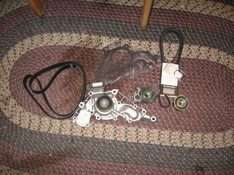
I purchased a timing belt kit on e-bay from a seller named volkstoy. I had heard good things about the kits on Tundrasolutions, so I bought one. It included the t-belt, water pump, gaskets, t-belt tensioner pulley, t-belt idler pulley, cam seals and crank seal(I did not replace the cam or crank seals because mine were not leaking), serpentine belt, along with a gasket and o-ring for the water inlet assembly, which is mounted atop the water pump. The belts are made by Bando, and the w/p and bearings are GMB. The set costs $230 and the shipping is free. Here is the set:
I have a Chilton's manual that I used for reference, even though I have done many t-belts on various other makes and models. A Toyota FSM would undoudtable be better, but the Chilton's was actually pretty complete. Be sure to have a manual before you start this job because it is pretty involved. Basic hand tools are needed for this job. Most of the fasteners are of the 10mm, 12mm, and 14mm variety. I used my 1/2 impact to loosen the crank bolt, and I needed to use my harmonic balancer/steering wheel puller to get the crank pulley off.
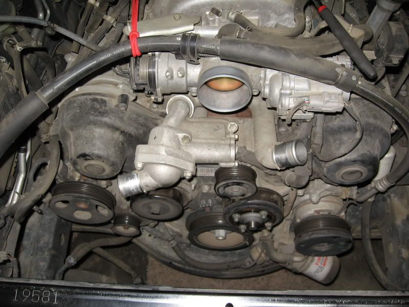
First, I disconnected the negative battery cable, removed the skid plate and drained the radiator. Then I removed the air intake tube, fan shroud, and radiator, then the fan itself. After that stuff is removed, you can start to see what you are up against to get the timing components removed:
Now it is time to start removing the timing belt covers and all the other stuff that is in the way. First, I removed the right side timing cover, the smaller timing cover next to it, and the serp belt idler pulley (all references to right and left are from the perspective of sitting in the driver's seat, and are completely opposite of how it looks when looking at the engine from standing in front of it. This is how my Chilton's manual is, so I have kept with that same orientation to avoid confusion for someone referencing this post and their manual simultaneously).
Then it was time to work on the left side timing cover. As shown in the following picture, there is more stuff to remove in order to get this side off. There is a coolant tube that goes from the water pump and tees off to the throttle body and down to the oil cooler (have a pan ready because even though the radiator is empty, there is a bunch of coolant waiting to spew forth once the lower end of that tube is removed). There is also a wire lead (for the cam sensor)coming through a grommeted hole in the cover on this side that needs to be dealt with. Here is how it looks:
And with the coolant pipe and that cover removed:
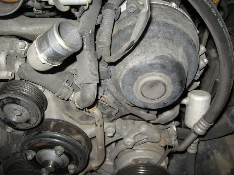
Next I removed the fan bracket. The a/c compressor mount ties into this bracket, so I found it necessary to remove two bolts holding the a/c compressor to the fan bracket.
On the other side, I removed the serp belt tensioning pulley assembly. The alternator must be removed in order to get it off. In order to get the alternator off, one needs to remove the power steering pump. The p/s pump is removed by pulling two bolts and a nut from the front of the pump; there are holes in the pulley, so you can even acces them with a socket. Pull the p/s pump off (lay it to the front with the hoses till attached), then you can remove the alternator and lay it down below. There is no need to remove the wires, just move it enough so that it is out of the way. Then I put the p/s pump back in place and loosly started the bolts and nut. It was not in the way of anything I needed to do after removing the alt. After that is done the tensioner assy comes right off.
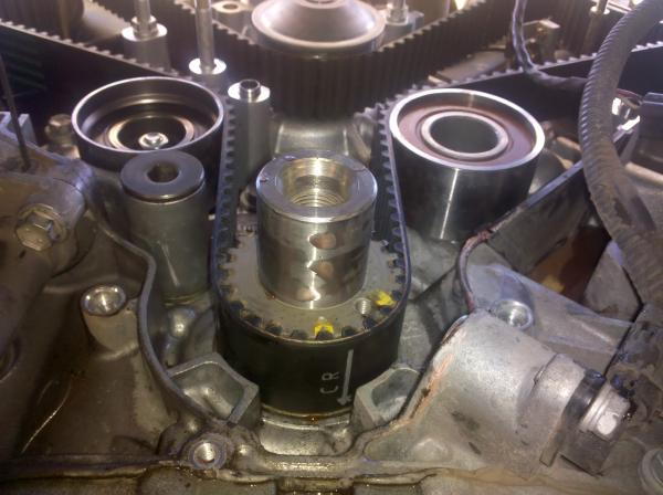
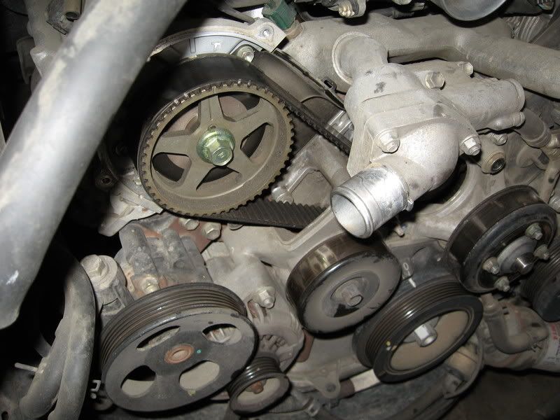
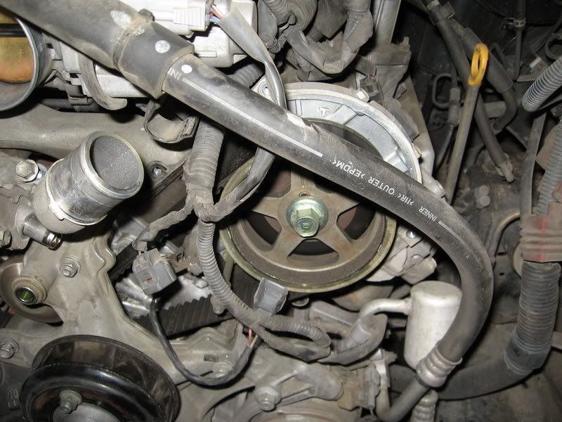
At this point I rotated the engine around to TDC on cyl#1. I insured that I was on the compression stroke by looking at the now exposed timing marks on the camshaft sprockets. On each side of the backing plate behind the cam sprocket there is a vertical mark and a "T". The vertical mark is TDC and the "T" is a mark you will use while installing the belt. You can see the marks on the pictures above.
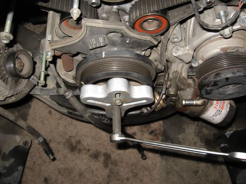
When that was done, I used my impact with a 22mm socket to remove the crank pulley bolt. At this point I should mention that this can be the single most frustrating part of this job if you don't have the right tools. The bolt is pretty tight, comparatively speaking. An impact will usually just zip it right off, but it is much harder to do with a breaker bar because the engine wants to turn instead of the bolt loosening. Usually you have to hold the pulley with a special pulley holding tool, or a chain wrench wrapped around the pulley. It can be a RPITA, so be prepared to mess with it a bit if you have never removed a crankshaft bolt. There is another method which uses a breaker bar up against the frame and bumping the starter. I don't do it this way because it has the potential to be dangerous and damaging. IF YOU DO DECIDE TO DO IT THIS WAY, DISABLE THE IGNITION SYSTEM SO THE ENGINE WILL NOT START WHILE "BUMPING THE STARTER".
With the bolt out, I used my harmonic balancer pulley to get the pulley off (you can borrow or rent a puller from many auto parts stores):
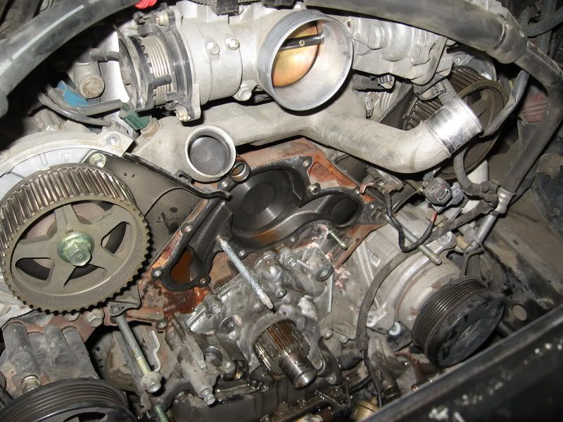
Now it was time to remove the small cover around the crankshaft, and you can see that the belt and water pump are next:
First the t-belt. I removed the t-belt tensioner by removing the two bolts that hold it on. It is seperate from the tensioner pulley and with it removed there is no tension on the pulley and belt. I didn't get any pics of that process, but the belt comes right off after that. The I removed the t-belt tensioner pulley and the idler pully.
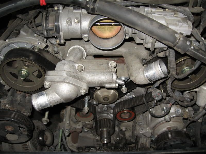
Now I still had the water inlet housing attached to the w/p as seen in the above pictures. It comes off by removing the two bolts angling downward from the top. It has a silicone seal and an o-ring holding it together and mine was tough to get off. I finally had to nudge it with a rubber mallet to get it freed up enough to twist it back and forthe enough to wiggle it off. The o-ring bore is a tight fit and makes it feel like you forgot to remove a bolt or something. When it is off it looks like this:

Now you can remove the w/p. Keep track of where all of the bolts and studs go. You will notice that you removed one of the bolts earlier when you removed the small cover. The rest of them are small bolts or studs which have the nuts already removed during prior disassebly of the tensioner pulley and the fan bracket. Have your drain pan positioned under the w/p because it is a gusher. Here is what it looks like when it is off:
When I got my belt and pulley off, I noticed a couple of things. First, the belt looked like it was still in fairly decent shape, with no obvious areas of concern. I know some people have tempted fate and ran them for many miles over what I did. My w/p was a different story. I could see some pink concretions under the pulley and at the weep hole that were casued by coolant leakage. Slight leakage, but leakage non-the-less. This crumby picture shows what I am talking about, sorry it it so blurry:
I imagine that if I had neglected to do this preventative maintenance, the water pump would have sprung a serious leak sometime in the near future. I'm sure it would have failed and required teardown before the timing belt broke anyway, if I had not performed this repair. If I had decided to just do the t-belt and not mess with the w/p, I would have been tearing it all apart again to replace the w/p. obviously, this is why it is best to get it all in one shot, and the extra expense is worth it. I got lazy and elected not to replace the crankshaft and camshaft seals. They were completely leak free, so I decided to let sleeping dogs lie. I hope it doesn't come back to bite me!
Next I cleaned the gasket surface and installed the w/p and gasket with black RTV. Then I installed the new idler and tensioner pullies. Now for the belt.
I mentioned earlier that I have replaced t-belts on a number of different makes and models. Many of them have little tricks and techniques to get everything all set up correctly, and this one is no different. I recommend reading and re-reading your manual before you start setting up the cam timing because it is a critical step.
It is easiest to do this if you have an extra arm extending from the center of your chest, but if not, a frind can help you hold the t-belt while you get it all lined up and indexed. The process on this engine goes as follows:
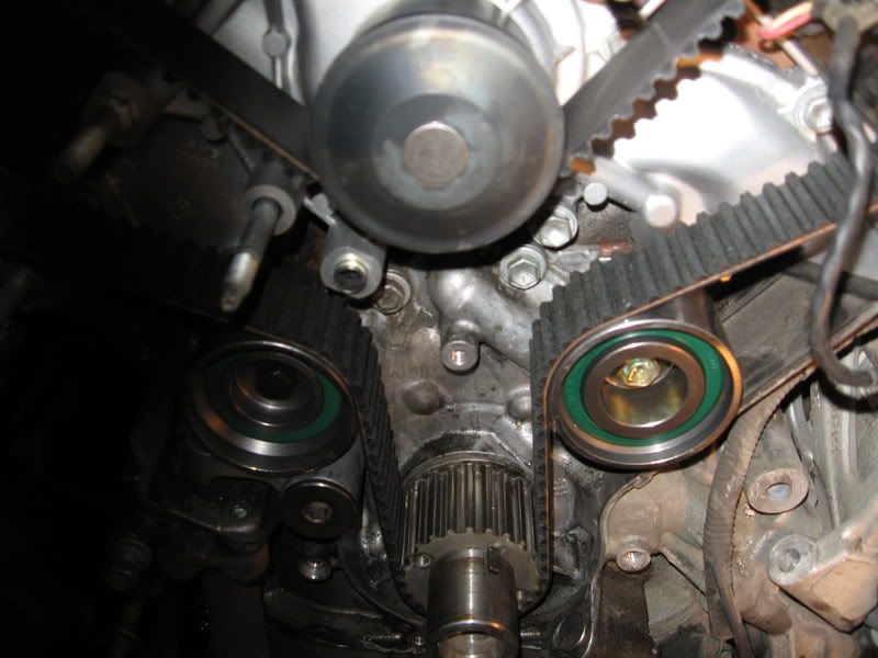
The new timing belt should have marks on it that correspond to the marks on the cam sprockets and the crank sprocket. The references are from sitting in the drivers seat, so they are reversed from the way you are looking at it and that can get confusing. Make sure that the crank is at TDC by referencing a groove on the upper side of the crank sprocket and a raised dimple on the oil pump housing( I regretfully didn't get a good pic of that mark, but you will see it and understand immediately). Start by positioning the left cam sprocket (on your right side) at the "T" position and then install the belt so the line on the belt matches up with the line on the sprocket. Have a helper hold the belt on the cam sprocket so it does not move, then route the belt onto the crank sprocket so that the line on the belt is in line with the dot on the lower side (this is not the crank TDC reference I mentioned above. It is a seperate mark which can be seen on the lower side front of the crank sprocket). Only those two sprockets are engaged with the belt at this point. Now you need to use a 17mm wrench on the cam sprocket and gently rotate the mark on the sprocket so it lines up with the straight line on the backing plate. That will take up all the slack in the belt between the cam sprocket and the crank sprocket. You can now position the right side (again, it is on your left) cam sprocket on the "T" mark and finish routing the t-belt onto it and around the tensioner and idler. Make sure the line on the belt is lined up with the mark on the sprocket, then gently rotate the cam sprocket so that the mark on it lines up with the straight line on the backing plate. That will put tension on the belt between the two cam sprockets and conveniently put all the slack on the side of the belt adjacent to the tensioner.
A few words about the tensioner. When I removed mine, I tested it by trying to push the now extended rod back into the body by holding it against my bench vise and leaning my body weight against it. It didn't budge and therefore appeared to be satisfactory. Then I had to get it ready to reinstall. I forgot to get pics of this process as well, but it is in the manual. I placed the tensioner in my vice so that when I turned the handle it would compress the shaft into the body. There is a hole in the shaft that lines up with a hole in the tensioner body when compressed. I inserted a small nail in the hole to hold the shaft in the body until assembly. I then bolted the tensioner onto the bracket and pulled the nail out which allows the tensioner to apply tension to the belt. It looked like this when I was all done. The tensioner is barely seen on the bottom left of the photo. The shaft pushes straight up on the tensioner pulley assenbly.
After I made sure the marks were all lined up properly, I temporarily reinstalled the crankshaft bolt and used a 22mm socket on a ratchet to rotate the engine two complete revolutions. This should bring everything back into place for a quick double check of the cam timing. The notch and bump on the crank pulley are in place and the mark on the cam sprockets are lined up with the straight lines on the backing plates. The lines on the belt are no longer in place, but that is normal and not a point of concern. They are there as a reference for installation only, and as long as the marks on the sprockets themselves line up all is well.
Now it is just a matter of doing all of the teardown steps in reverse order until it is all back together. I lubed the o-ring on the water inlet housing with antifreeze in order to get it to go back together smoothly, and every thing buttoned back up nicely. I filled it with Toyota red antifreeze, changed the oil just because and started it up. As with other Yota pickups, the Tundra is kind of tricky to get the air pocket out of the heater core (burped). I had the Tundra running (heater on full blast)with the radiator cap off on my inclined driveway, but ended up jacking the front of the truck up another foot in order to get it to burp. You can tell when it burps because it will start spewing air and hot coolant out of the radiator filler and the air will finally star to feel warm coming out of the vents. When all of the air is burped out, you can finish filling the radiator and you are done.
The finished product-ready for many more miles of trouble free service:

I purchased a timing belt kit on e-bay from a seller named volkstoy. I had heard good things about the kits on Tundrasolutions, so I bought one. It included the t-belt, water pump, gaskets, t-belt tensioner pulley, t-belt idler pulley, cam seals and crank seal(I did not replace the cam or crank seals because mine were not leaking), serpentine belt, along with a gasket and o-ring for the water inlet assembly, which is mounted atop the water pump. The belts are made by Bando, and the w/p and bearings are GMB. The set costs $230 and the shipping is free. Here is the set:
I have a Chilton's manual that I used for reference, even though I have done many t-belts on various other makes and models. A Toyota FSM would undoudtable be better, but the Chilton's was actually pretty complete. Be sure to have a manual before you start this job because it is pretty involved. Basic hand tools are needed for this job. Most of the fasteners are of the 10mm, 12mm, and 14mm variety. I used my 1/2 impact to loosen the crank bolt, and I needed to use my harmonic balancer/steering wheel puller to get the crank pulley off.
First, I disconnected the negative battery cable, removed the skid plate and drained the radiator. Then I removed the air intake tube, fan shroud, and radiator, then the fan itself. After that stuff is removed, you can start to see what you are up against to get the timing components removed:
Now it is time to start removing the timing belt covers and all the other stuff that is in the way. First, I removed the right side timing cover, the smaller timing cover next to it, and the serp belt idler pulley (all references to right and left are from the perspective of sitting in the driver's seat, and are completely opposite of how it looks when looking at the engine from standing in front of it. This is how my Chilton's manual is, so I have kept with that same orientation to avoid confusion for someone referencing this post and their manual simultaneously).
Then it was time to work on the left side timing cover. As shown in the following picture, there is more stuff to remove in order to get this side off. There is a coolant tube that goes from the water pump and tees off to the throttle body and down to the oil cooler (have a pan ready because even though the radiator is empty, there is a bunch of coolant waiting to spew forth once the lower end of that tube is removed). There is also a wire lead (for the cam sensor)coming through a grommeted hole in the cover on this side that needs to be dealt with. Here is how it looks:
And with the coolant pipe and that cover removed:
Next I removed the fan bracket. The a/c compressor mount ties into this bracket, so I found it necessary to remove two bolts holding the a/c compressor to the fan bracket.
On the other side, I removed the serp belt tensioning pulley assembly. The alternator must be removed in order to get it off. In order to get the alternator off, one needs to remove the power steering pump. The p/s pump is removed by pulling two bolts and a nut from the front of the pump; there are holes in the pulley, so you can even acces them with a socket. Pull the p/s pump off (lay it to the front with the hoses till attached), then you can remove the alternator and lay it down below. There is no need to remove the wires, just move it enough so that it is out of the way. Then I put the p/s pump back in place and loosly started the bolts and nut. It was not in the way of anything I needed to do after removing the alt. After that is done the tensioner assy comes right off.
At this point I rotated the engine around to TDC on cyl#1. I insured that I was on the compression stroke by looking at the now exposed timing marks on the camshaft sprockets. On each side of the backing plate behind the cam sprocket there is a vertical mark and a "T". The vertical mark is TDC and the "T" is a mark you will use while installing the belt. You can see the marks on the pictures above.
When that was done, I used my impact with a 22mm socket to remove the crank pulley bolt. At this point I should mention that this can be the single most frustrating part of this job if you don't have the right tools. The bolt is pretty tight, comparatively speaking. An impact will usually just zip it right off, but it is much harder to do with a breaker bar because the engine wants to turn instead of the bolt loosening. Usually you have to hold the pulley with a special pulley holding tool, or a chain wrench wrapped around the pulley. It can be a RPITA, so be prepared to mess with it a bit if you have never removed a crankshaft bolt. There is another method which uses a breaker bar up against the frame and bumping the starter. I don't do it this way because it has the potential to be dangerous and damaging. IF YOU DO DECIDE TO DO IT THIS WAY, DISABLE THE IGNITION SYSTEM SO THE ENGINE WILL NOT START WHILE "BUMPING THE STARTER".
With the bolt out, I used my harmonic balancer pulley to get the pulley off (you can borrow or rent a puller from many auto parts stores):
Now it was time to remove the small cover around the crankshaft, and you can see that the belt and water pump are next:
First the t-belt. I removed the t-belt tensioner by removing the two bolts that hold it on. It is seperate from the tensioner pulley and with it removed there is no tension on the pulley and belt. I didn't get any pics of that process, but the belt comes right off after that. The I removed the t-belt tensioner pulley and the idler pully.
Now I still had the water inlet housing attached to the w/p as seen in the above pictures. It comes off by removing the two bolts angling downward from the top. It has a silicone seal and an o-ring holding it together and mine was tough to get off. I finally had to nudge it with a rubber mallet to get it freed up enough to twist it back and forthe enough to wiggle it off. The o-ring bore is a tight fit and makes it feel like you forgot to remove a bolt or something. When it is off it looks like this:
Now you can remove the w/p. Keep track of where all of the bolts and studs go. You will notice that you removed one of the bolts earlier when you removed the small cover. The rest of them are small bolts or studs which have the nuts already removed during prior disassebly of the tensioner pulley and the fan bracket. Have your drain pan positioned under the w/p because it is a gusher. Here is what it looks like when it is off:
When I got my belt and pulley off, I noticed a couple of things. First, the belt looked like it was still in fairly decent shape, with no obvious areas of concern. I know some people have tempted fate and ran them for many miles over what I did. My w/p was a different story. I could see some pink concretions under the pulley and at the weep hole that were casued by coolant leakage. Slight leakage, but leakage non-the-less. This crumby picture shows what I am talking about, sorry it it so blurry:
I imagine that if I had neglected to do this preventative maintenance, the water pump would have sprung a serious leak sometime in the near future. I'm sure it would have failed and required teardown before the timing belt broke anyway, if I had not performed this repair. If I had decided to just do the t-belt and not mess with the w/p, I would have been tearing it all apart again to replace the w/p. obviously, this is why it is best to get it all in one shot, and the extra expense is worth it. I got lazy and elected not to replace the crankshaft and camshaft seals. They were completely leak free, so I decided to let sleeping dogs lie. I hope it doesn't come back to bite me!
Next I cleaned the gasket surface and installed the w/p and gasket with black RTV. Then I installed the new idler and tensioner pullies. Now for the belt.
I mentioned earlier that I have replaced t-belts on a number of different makes and models. Many of them have little tricks and techniques to get everything all set up correctly, and this one is no different. I recommend reading and re-reading your manual before you start setting up the cam timing because it is a critical step.
It is easiest to do this if you have an extra arm extending from the center of your chest, but if not, a frind can help you hold the t-belt while you get it all lined up and indexed. The process on this engine goes as follows:
The new timing belt should have marks on it that correspond to the marks on the cam sprockets and the crank sprocket. The references are from sitting in the drivers seat, so they are reversed from the way you are looking at it and that can get confusing. Make sure that the crank is at TDC by referencing a groove on the upper side of the crank sprocket and a raised dimple on the oil pump housing( I regretfully didn't get a good pic of that mark, but you will see it and understand immediately). Start by positioning the left cam sprocket (on your right side) at the "T" position and then install the belt so the line on the belt matches up with the line on the sprocket. Have a helper hold the belt on the cam sprocket so it does not move, then route the belt onto the crank sprocket so that the line on the belt is in line with the dot on the lower side (this is not the crank TDC reference I mentioned above. It is a seperate mark which can be seen on the lower side front of the crank sprocket). Only those two sprockets are engaged with the belt at this point. Now you need to use a 17mm wrench on the cam sprocket and gently rotate the mark on the sprocket so it lines up with the straight line on the backing plate. That will take up all the slack in the belt between the cam sprocket and the crank sprocket. You can now position the right side (again, it is on your left) cam sprocket on the "T" mark and finish routing the t-belt onto it and around the tensioner and idler. Make sure the line on the belt is lined up with the mark on the sprocket, then gently rotate the cam sprocket so that the mark on it lines up with the straight line on the backing plate. That will put tension on the belt between the two cam sprockets and conveniently put all the slack on the side of the belt adjacent to the tensioner.
A few words about the tensioner. When I removed mine, I tested it by trying to push the now extended rod back into the body by holding it against my bench vise and leaning my body weight against it. It didn't budge and therefore appeared to be satisfactory. Then I had to get it ready to reinstall. I forgot to get pics of this process as well, but it is in the manual. I placed the tensioner in my vice so that when I turned the handle it would compress the shaft into the body. There is a hole in the shaft that lines up with a hole in the tensioner body when compressed. I inserted a small nail in the hole to hold the shaft in the body until assembly. I then bolted the tensioner onto the bracket and pulled the nail out which allows the tensioner to apply tension to the belt. It looked like this when I was all done. The tensioner is barely seen on the bottom left of the photo. The shaft pushes straight up on the tensioner pulley assenbly.
After I made sure the marks were all lined up properly, I temporarily reinstalled the crankshaft bolt and used a 22mm socket on a ratchet to rotate the engine two complete revolutions. This should bring everything back into place for a quick double check of the cam timing. The notch and bump on the crank pulley are in place and the mark on the cam sprockets are lined up with the straight lines on the backing plates. The lines on the belt are no longer in place, but that is normal and not a point of concern. They are there as a reference for installation only, and as long as the marks on the sprockets themselves line up all is well.
Now it is just a matter of doing all of the teardown steps in reverse order until it is all back together. I lubed the o-ring on the water inlet housing with antifreeze in order to get it to go back together smoothly, and every thing buttoned back up nicely. I filled it with Toyota red antifreeze, changed the oil just because and started it up. As with other Yota pickups, the Tundra is kind of tricky to get the air pocket out of the heater core (burped). I had the Tundra running (heater on full blast)with the radiator cap off on my inclined driveway, but ended up jacking the front of the truck up another foot in order to get it to burp. You can tell when it burps because it will start spewing air and hot coolant out of the radiator filler and the air will finally star to feel warm coming out of the vents. When all of the air is burped out, you can finish filling the radiator and you are done.
The finished product-ready for many more miles of trouble free service:

 04-04-2012, 08:45 PM
#40
Registered User

Join Date: Nov 2008
Location: Bakersfield California
Posts: 32
Likes: 0
Received 0 Likes
on
0 Posts
Good info
Used this today to change my waterpump and timing belt on my 2006. I went with aisin pump and bearings but I need to do my 3.4 4runner and I curious to what everyone has to say about the GMB products.


