Yakima LoadWarrior "Build" Thread
 02-24-2011, 06:29 AM
#1
Yakima LoadWarrior "Build" Thread
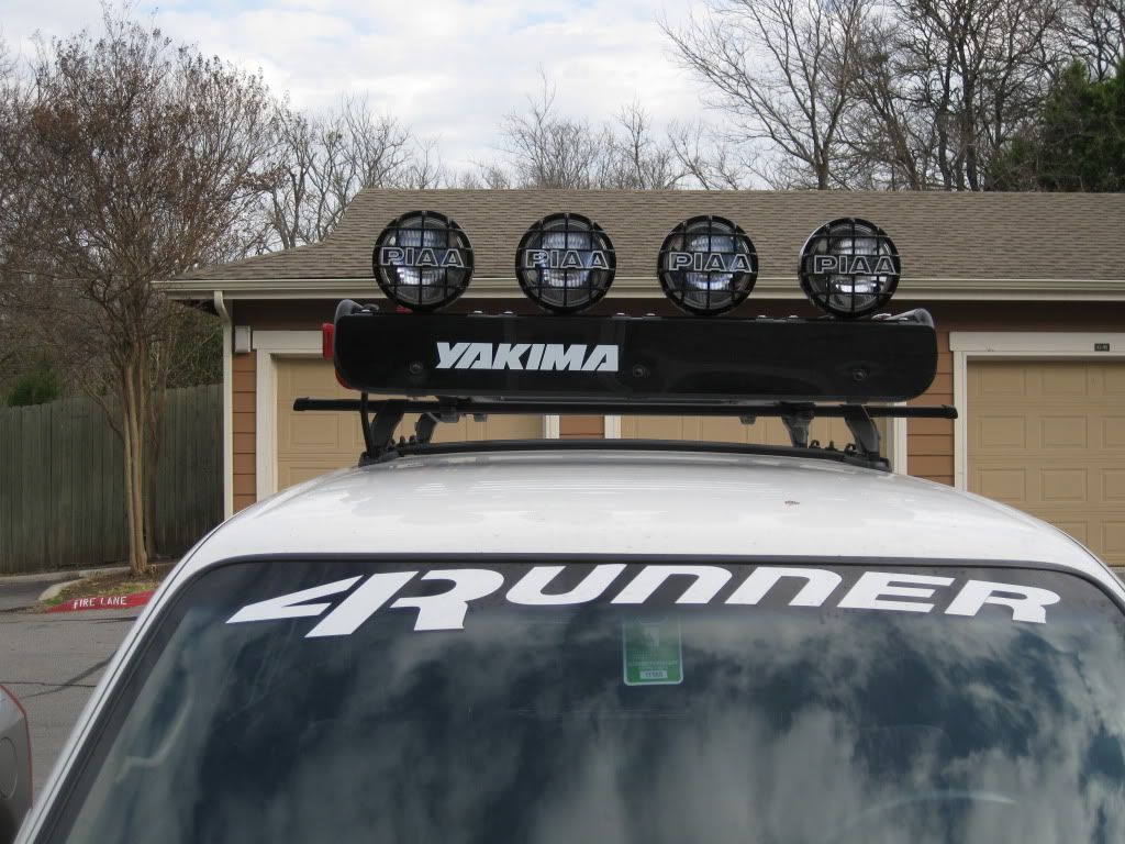
I just thought that I would share some pics and info about my LoadWarrior "build". I have been slowly piecing together my Yakima LoadWarrior and all the accessories for a while, but now that I am close to being done with it, I thought I would share what I have.
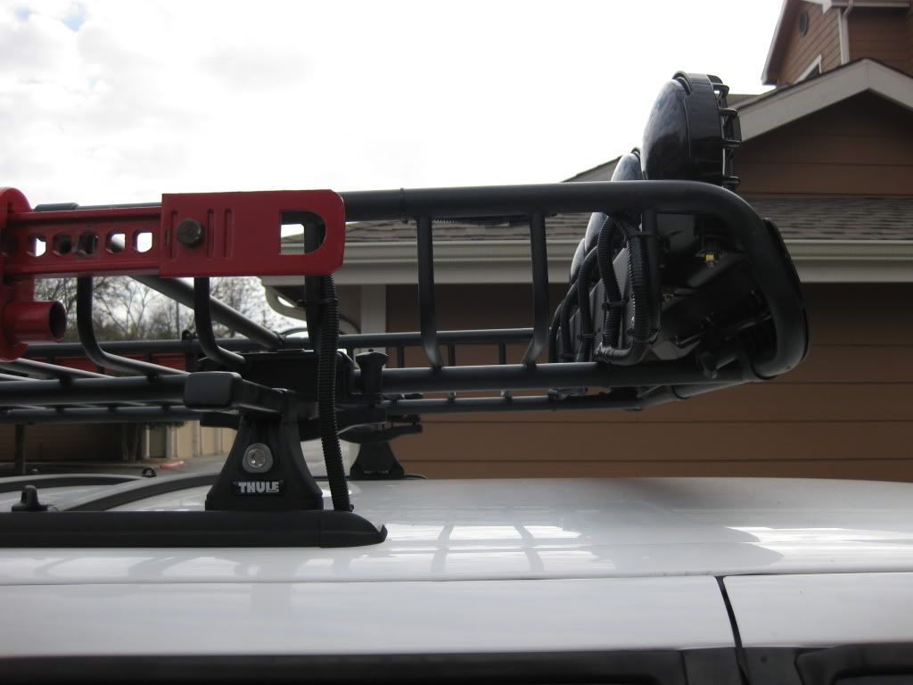
Thule 43050 Complete Tracker II rack system - $50 (BRAND NEW!!) on Craigslist
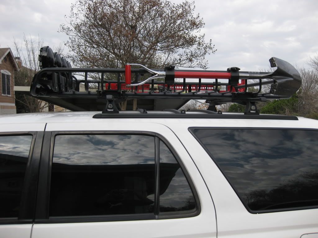
Yakima LoadWarrior basket, Hi-lift mount, and Shovel/Axe mount - $125 on Craigslist
Yakima LoadWarrior Extenstion - $120 from a local store
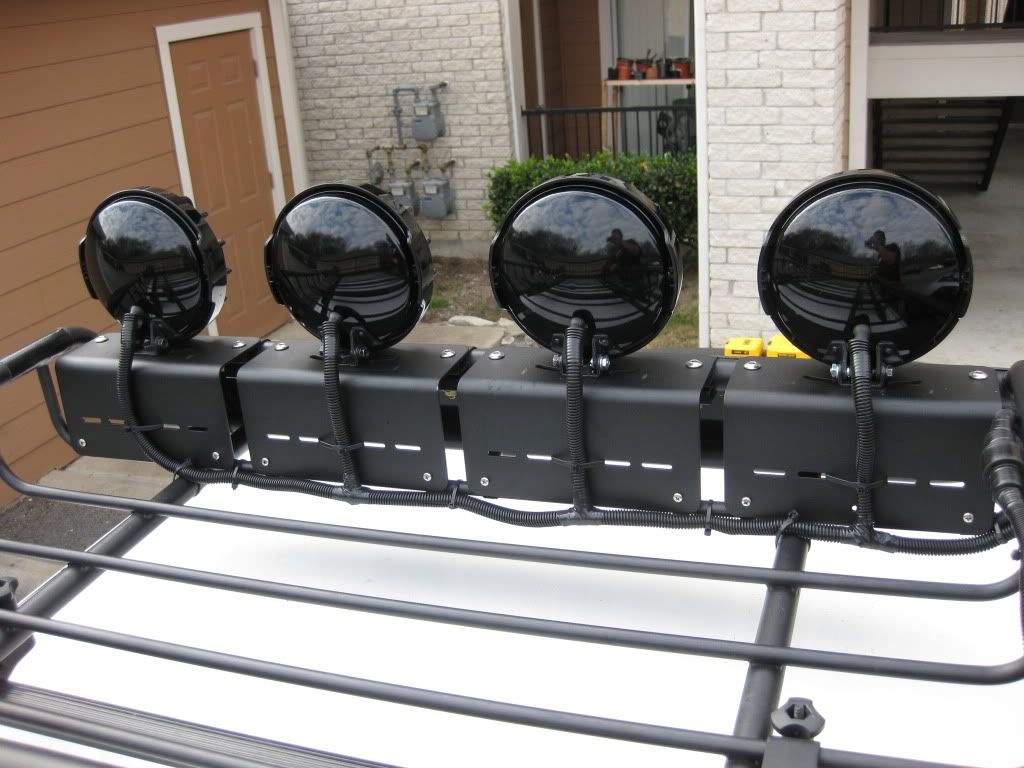
Yakima Light Mounts - $80 (~$40 per pair) from ORS Racks Direct
PIAA 520 ATP's - $400 (~$200 per pair) on eBay
48" Hi-Lift jack - $40 on Craigslist
Shovel - $20 at Lowes
PICS:
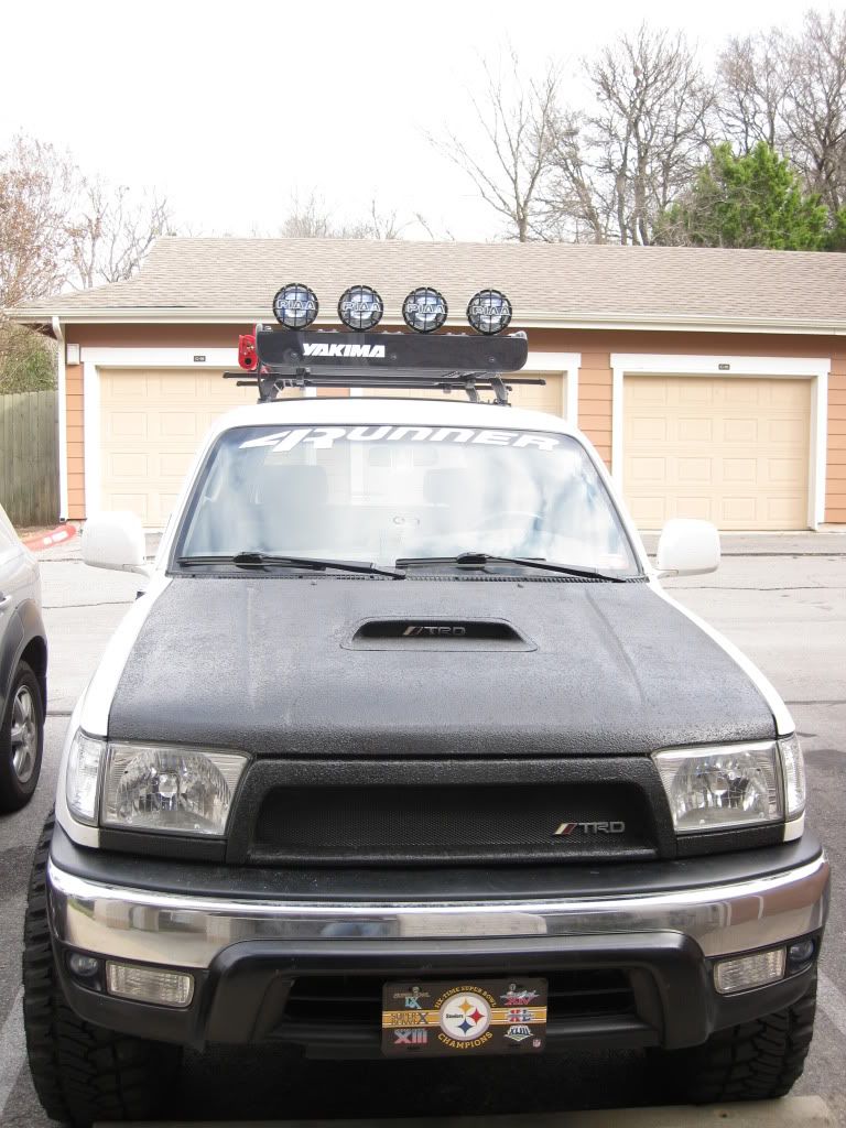
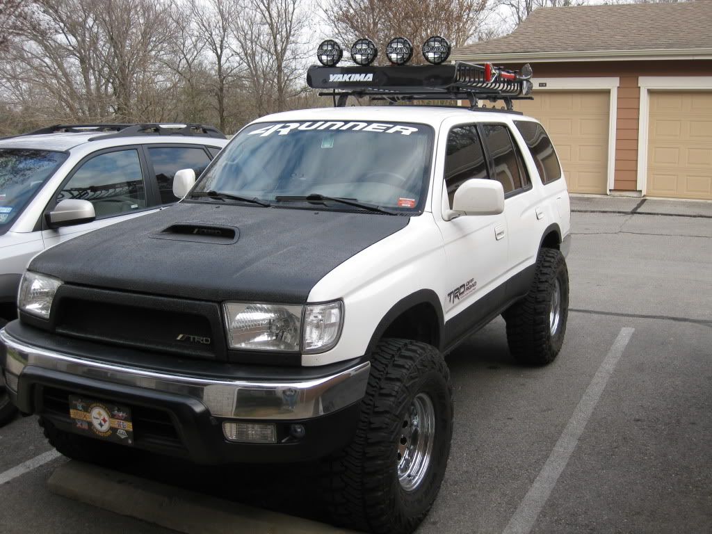
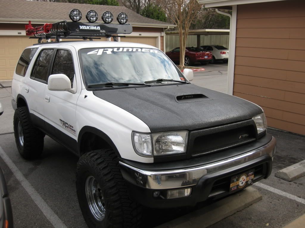
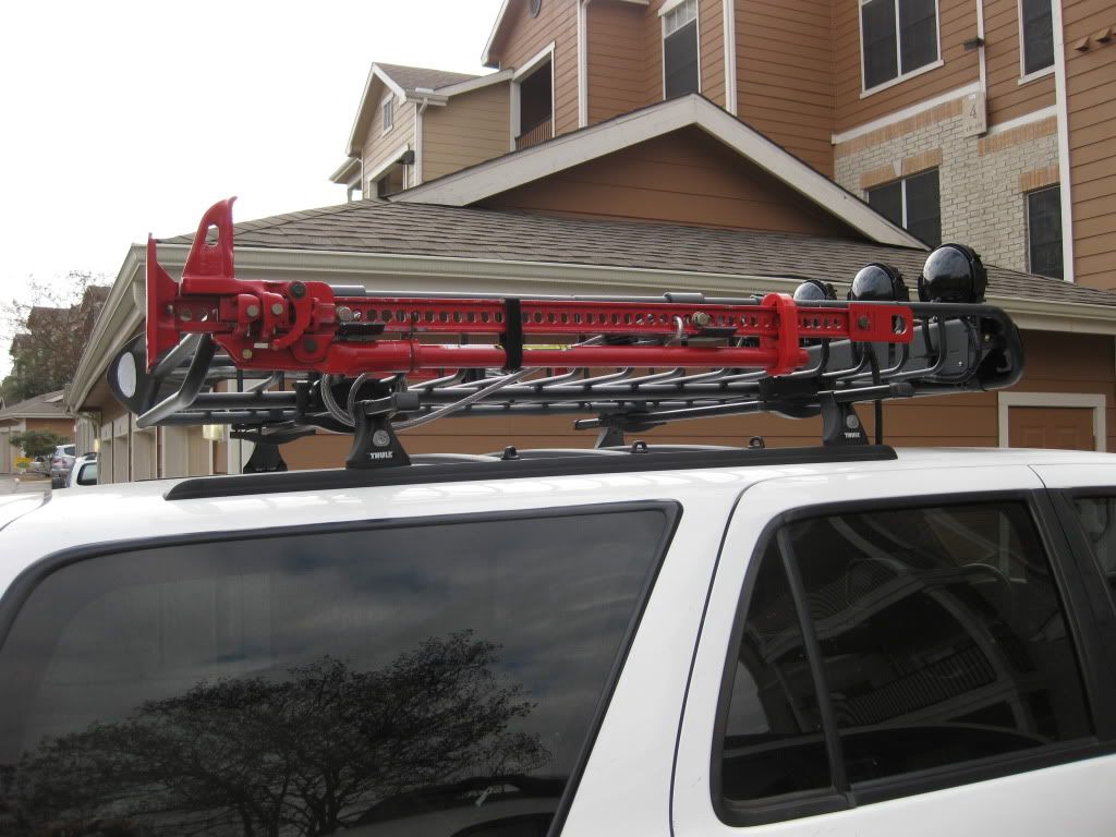
I had a Jerry Can mounted on the rack but I just recently installed the lights and they interfeared with the Jerry Can so I had to remove the Jerry Can, but I am hoping to reinstall it this weekend. I also got a Yakima spare tire mount for Christmas so now I am saving up for a spare wheel and tire so I can mount it on the rack. Finally, I will share some more detail and pics that show how I wired up the lights for anyone who is interested in doing something similar because it is not as easy as I though it was going to be and I got a lot of help from other YT members!
Thule 43050 Complete Tracker II rack system - $50 (BRAND NEW!!) on Craigslist
Yakima LoadWarrior basket, Hi-lift mount, and Shovel/Axe mount - $125 on Craigslist
Yakima LoadWarrior Extenstion - $120 from a local store
Yakima Light Mounts - $80 (~$40 per pair) from ORS Racks Direct
PIAA 520 ATP's - $400 (~$200 per pair) on eBay
48" Hi-Lift jack - $40 on Craigslist
Shovel - $20 at Lowes
PICS:
I had a Jerry Can mounted on the rack but I just recently installed the lights and they interfeared with the Jerry Can so I had to remove the Jerry Can, but I am hoping to reinstall it this weekend. I also got a Yakima spare tire mount for Christmas so now I am saving up for a spare wheel and tire so I can mount it on the rack. Finally, I will share some more detail and pics that show how I wired up the lights for anyone who is interested in doing something similar because it is not as easy as I though it was going to be and I got a lot of help from other YT members!
Last edited by 4ever4running; 02-24-2011 at 01:35 PM.
 02-24-2011, 08:16 AM
#4
Registered User
Join Date: Apr 2010
Location: Kingston, Ontario CANADA
Posts: 815
Likes: 0
Received 0 Likes
on
0 Posts
Very nice man. Your hood and grill/shroud also excellent. What type of paint did you use? I want to fix up my front grill shroud and get rid of that cheap looking chrome.
Mike
Mike
02-24-2011, 09:06 AM
#5
Thanks!!
Yeah it has taken me about 5 months to piece everything together. Keep an eye on Craigslist, there are deals to be found!!
Thanks! I actually used a product called Durabak. It is a truck bed liner with built in UV protection. Check out this thread I started after I bought the scooped hood: https://www.yotatech.com/forums/f2/f...t-next-221976/. I hope this helps.
02-24-2011, 03:29 PM
#7
Registered User
iTrader: (1)
Join Date: Jul 2009
Location: Central, Arkansas
Posts: 1,088
Likes: 0
Received 0 Likes
on
0 Posts
holy top end heavy!! Looks good, but however I rather spend the mega bucks it cost for all of that elsewhere like armor or something a little more useful. Good luck with all of that. When you decide you don't want it anymore cus you're mpg's drop I'll take those lights 
Trending Topics
02-24-2011, 03:56 PM
#8
Registered User
Join Date: Apr 2010
Location: Kingston, Ontario CANADA
Posts: 815
Likes: 0
Received 0 Likes
on
0 Posts
Thanks! I actually used a product called Durabak. It is a truck bed liner with built in UV protection. Check out this thread I started after I bought the scooped hood: https://www.yotatech.com/forums/f2/f...t-next-221976/. I hope this helps.[/quote]
Thanks buddy. I'm going to see if I can get that stuff up here. Good looking rig!
Thanks buddy. I'm going to see if I can get that stuff up here. Good looking rig!
02-24-2011, 05:00 PM
#9

Thanks! I actually used a product called Durabak. It is a truck bed liner with built in UV protection. Check out this thread I started after I bought the scooped hood: https://www.yotatech.com/forums/f2/f...t-next-221976/. I hope this helps.
No problem! Thanks! It has been a pretty lengthy process to get it where it is now, and there is always more to be done
 02-24-2011, 05:31 PM
#12
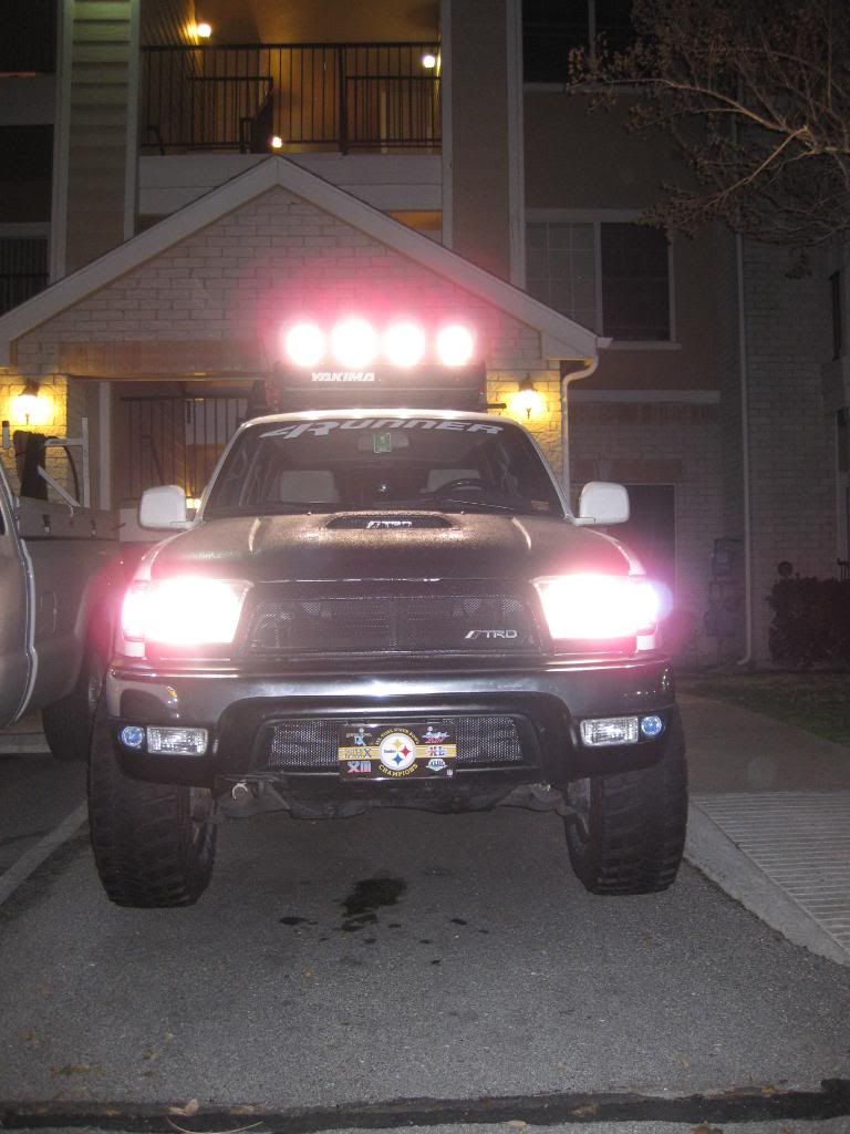
So here are a couple of night shots to give you an idea of just how bright these lights are. I have them aimed a little higher than the stock low and high beams to give me greater visibility down the road/trail.
Low beams:
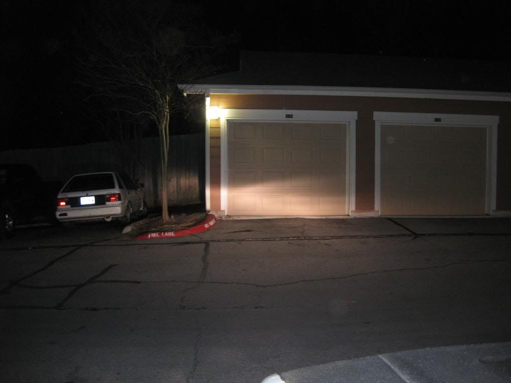
Low beams and PIAA's:
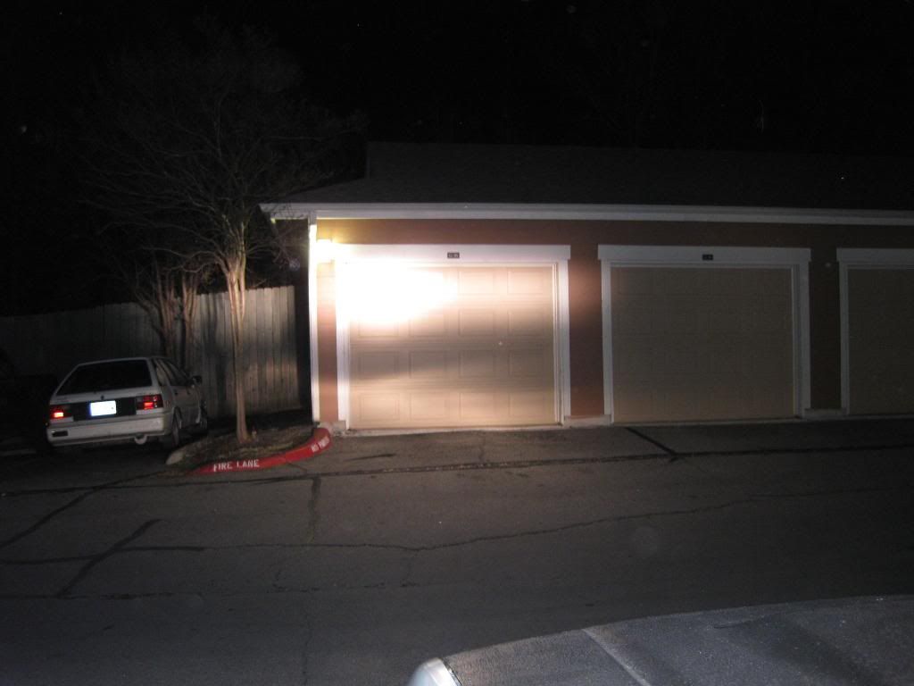

I tried to turn on the lower fog lamps to get a shot with everything on, but they wouldn't turn on. I did some searching and found out that I blew the fuse so I will have to pick up some more fuses tomorrow and get a shot with everything on.
Low beams:
Low beams and PIAA's:
I tried to turn on the lower fog lamps to get a shot with everything on, but they wouldn't turn on. I did some searching and found out that I blew the fuse so I will have to pick up some more fuses tomorrow and get a shot with everything on.
 02-25-2011, 10:02 AM
#15
As promised, here is some more info and pics of how I installed the lights and ran the wires.
Here is a wiring diagram that I put together for anyone interested in doing this project.
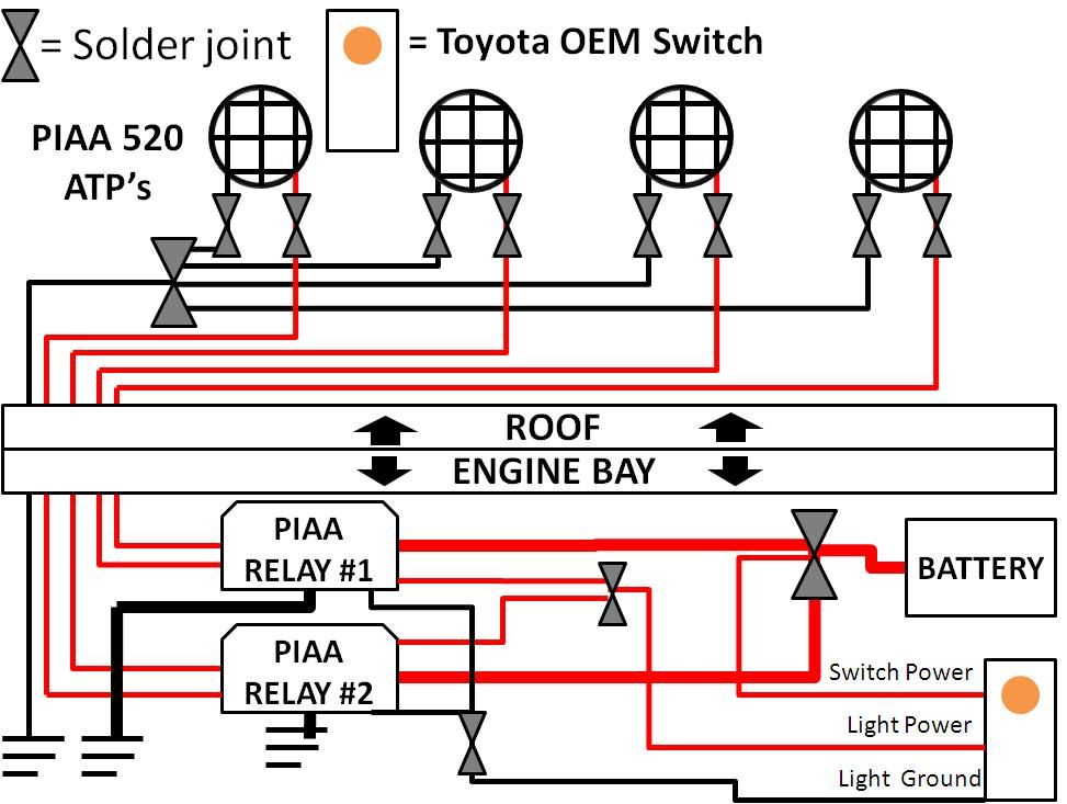
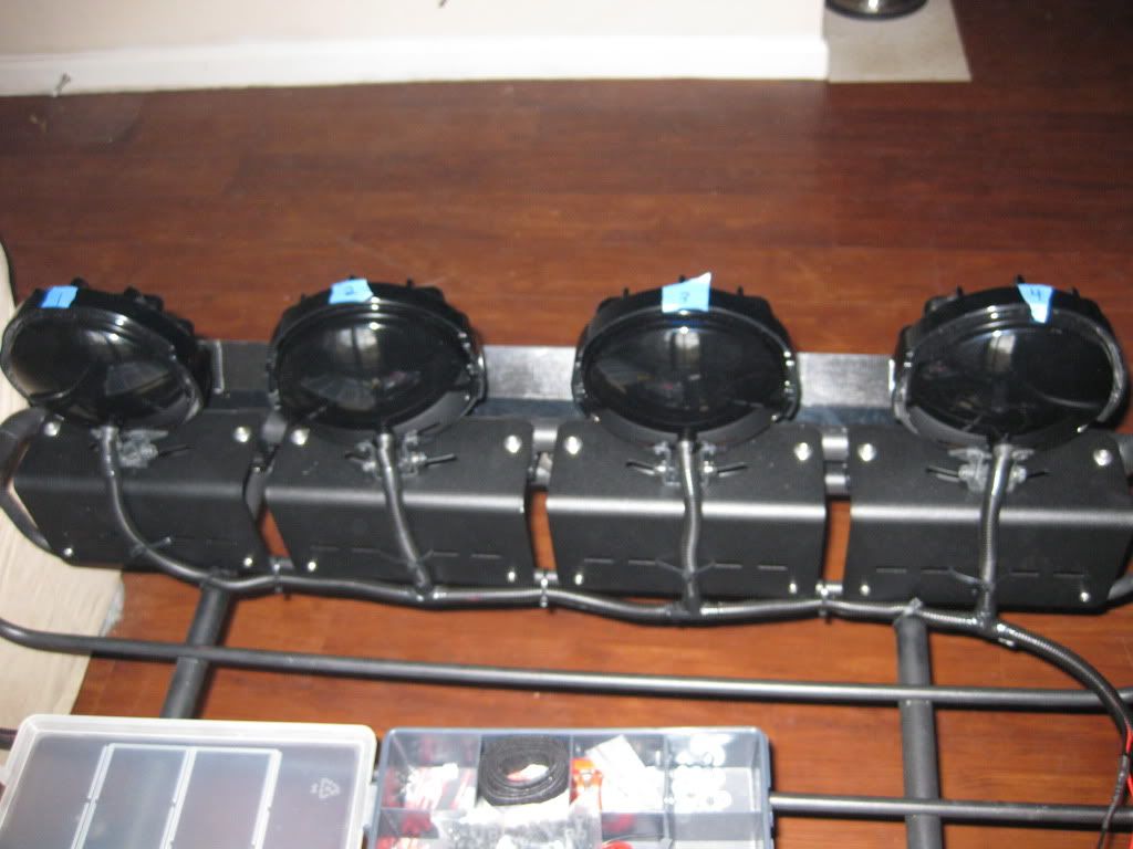
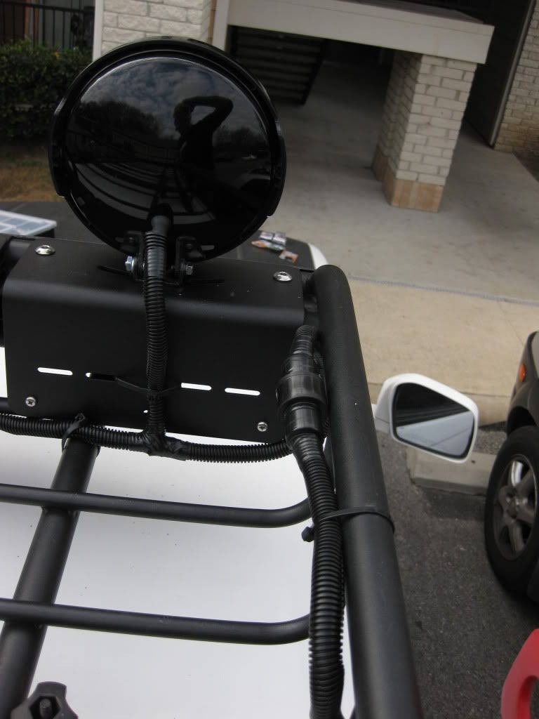
Fist I mounted the lights and modified the wiring harnesses for the PIAA's. I ended up cutting off the white male/female connectors for each light and soldered some 16 gauge wires to the ground and power wires for each light (red=power, black=ground). Then I wrapped the wires in some conduit to keep them organized and make the install look cleaner. I used zip ties to hold the wires/conduit to the rack.
Before running the wires down the roof and into the engine bay I did 2 things:
1) I soldered the 4 ground wires (1 from each light) together into one common 16 gauge ground wire.
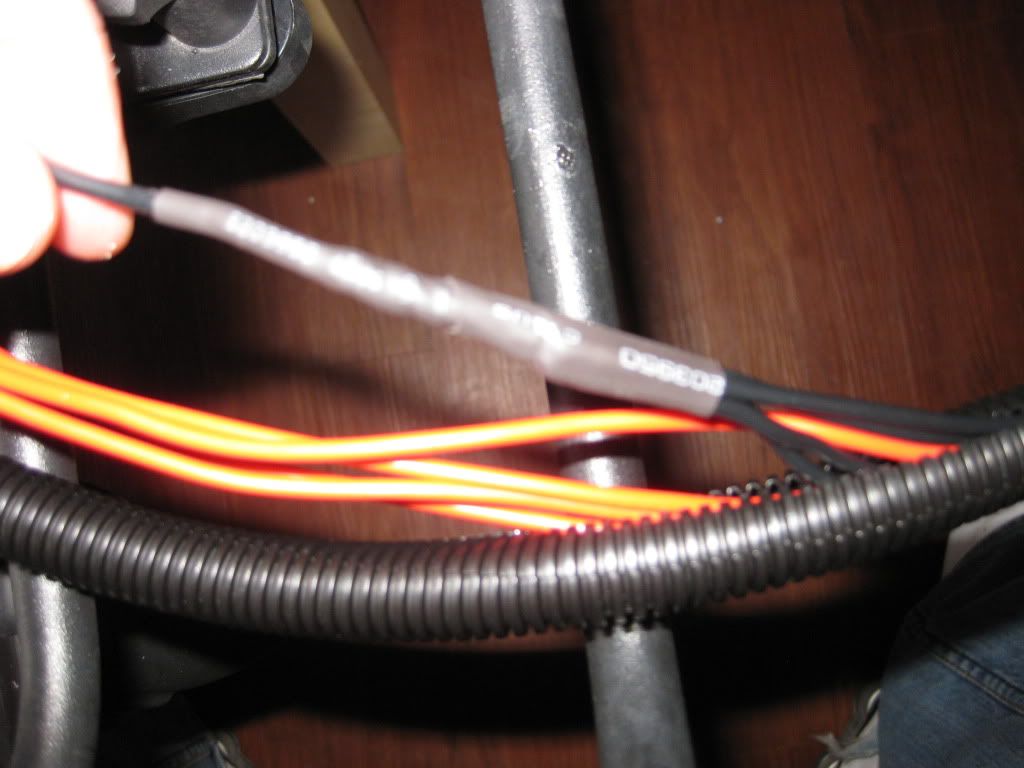
2) I installed a Sure Seal Connector which allows me to quickly disconnect the lights so I can easily remove the rack if I want/need to. The Sure Seal Connector is great but keep in mind that you have to make the connector yourself. I purchased the connector and required pins from this website: http://www.peigenesis.com/ I went with a 5 pin connector (4 power wires, 1 common ground wire) and 10 pins and 10 sockets. I didn't need all the pins and sockets but I wanted to make sure that I had extras just in case I messed up when assempling the plug and pins. Also, you will need a pair of "open barrel crimping pliars" in order to properly attach the pins and receptacles to your wires. I couldn't find them at any local store so I ended up ordering mine from here: http://www.coolerguys.com/8405560926...hannelid=FROOG
The specific model numbers of Sure Seal materials I used are as follows:
Plug: 120-1841-000
Receptacle: 120-1839-000
Pins: 030-2196-000 (or 001)
Sockets: 031-1267-000 (or 001)
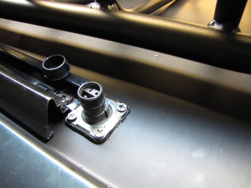
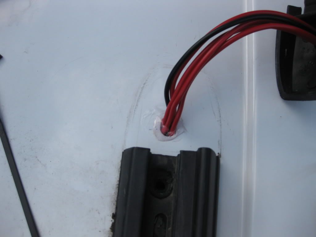
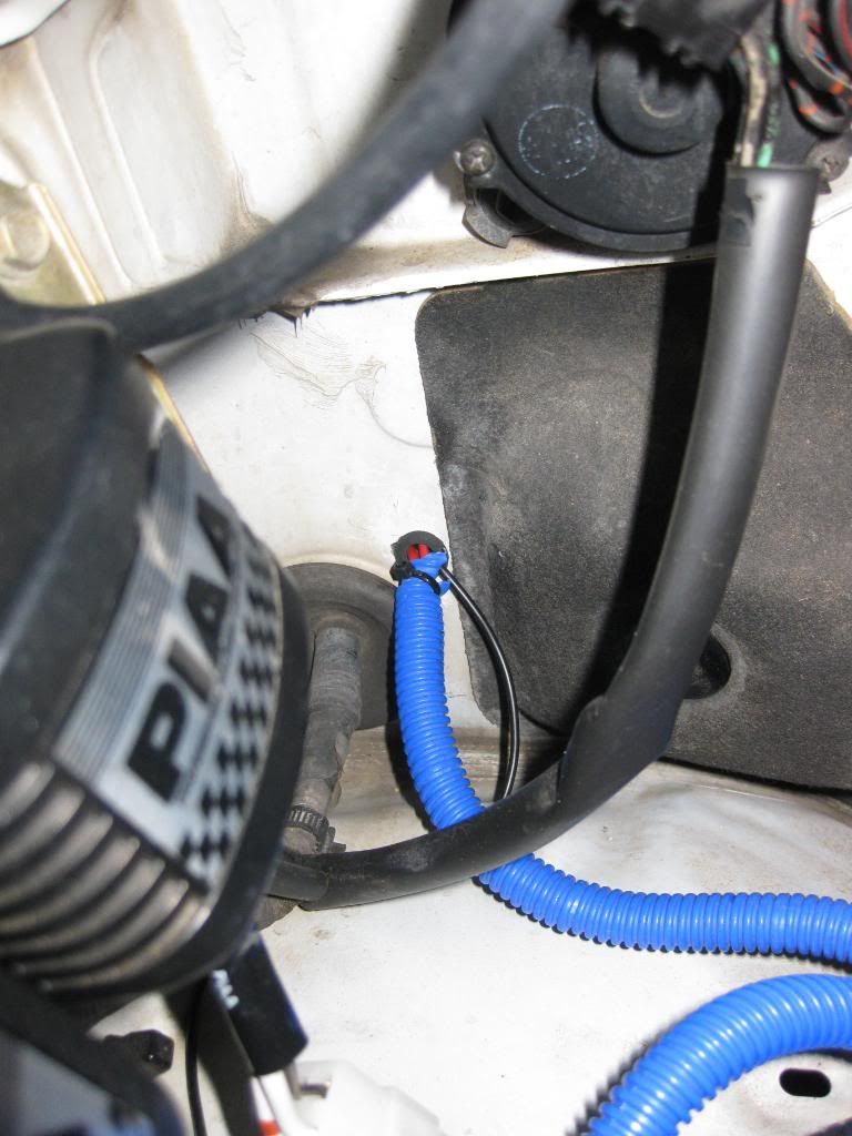
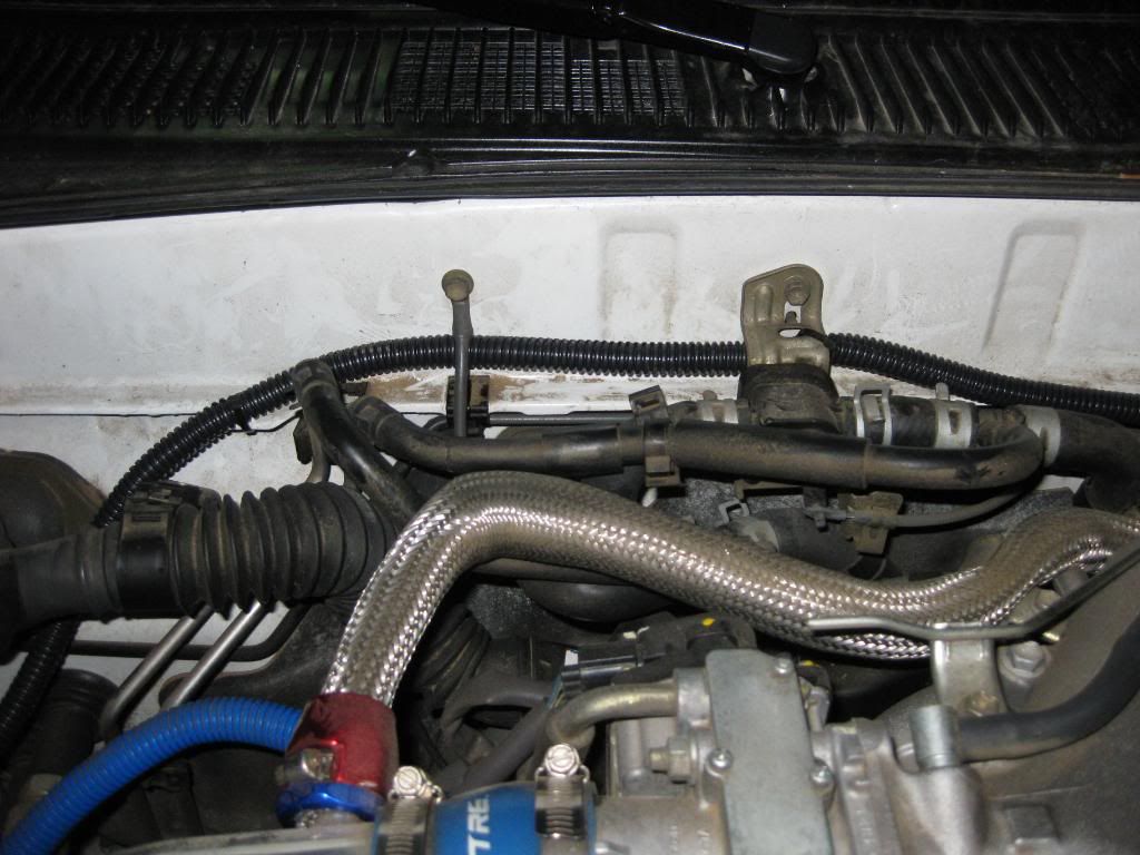
Then I ran some wires from the roof into the engine bay. I chose to run the wires down the passanger side A pillar because I already have a gauge pod on the driver side A pillar and I didn't want to have to run more wires down that way. I removed the end cap on the facory roof rails and pulled out the yellow plug. This is a perfect sized hole to run my 5-16 gauge wires. NOTE: Be sure to use some silicone sealant on the wires and the hole when you are done or you will have water seep through the headliner and into the cab!
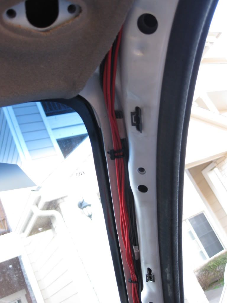
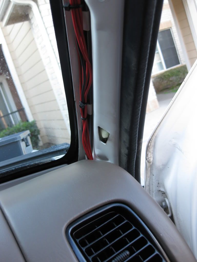
In order to access the hole from the inside I just had to remove the 3 "oh s***" bars and some of the to trim pieces. Once the trim pieces were out of the way, it was pretty easy to run the wires down the A pillar.
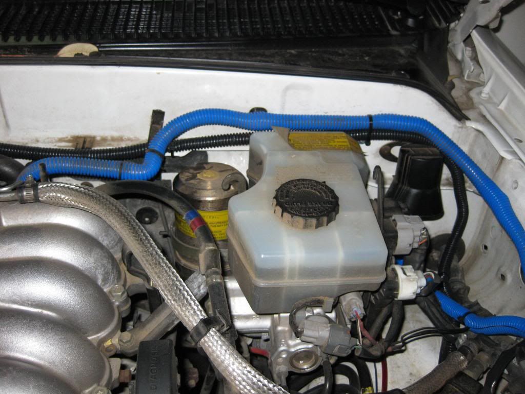
Then I drilled a hole in the firewall to run the wires into the engine bay. Be sure to use a rubber gromet to prevent any water from coming into the cab from the engine bay.
Then I mounted the relays where I wanted them and attached the ground wires to the body using self-tapping screws.
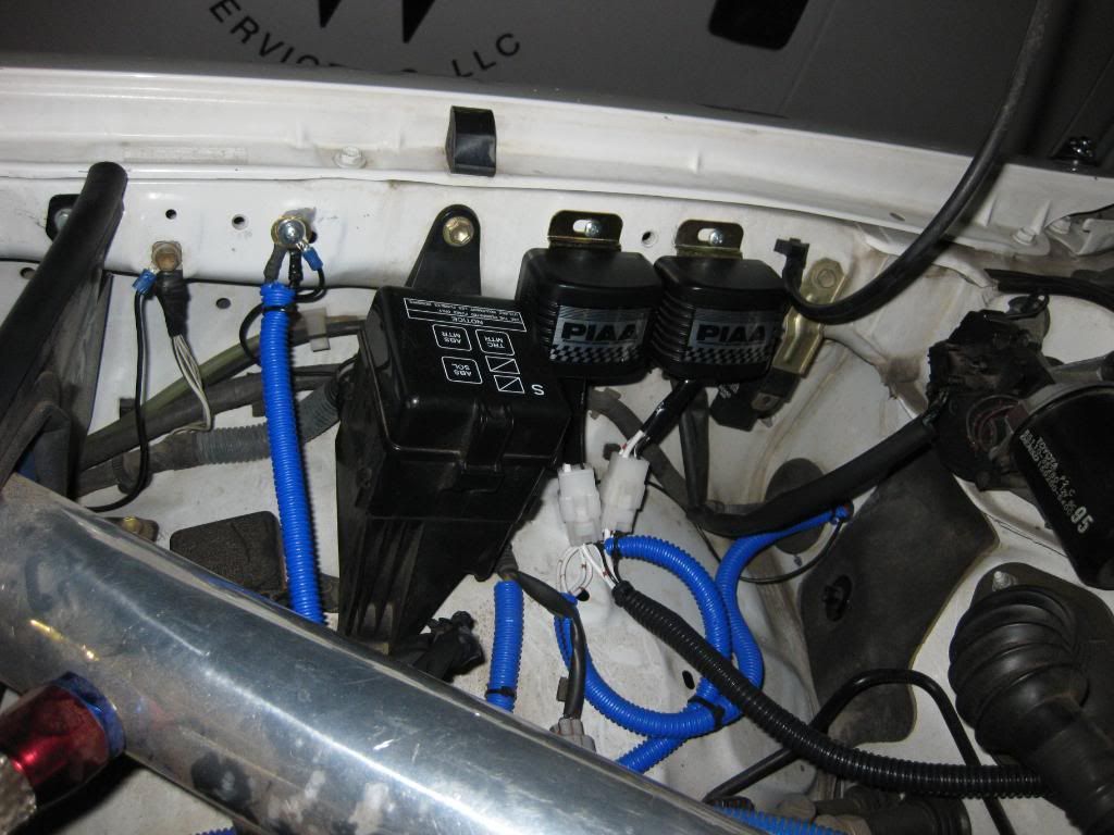
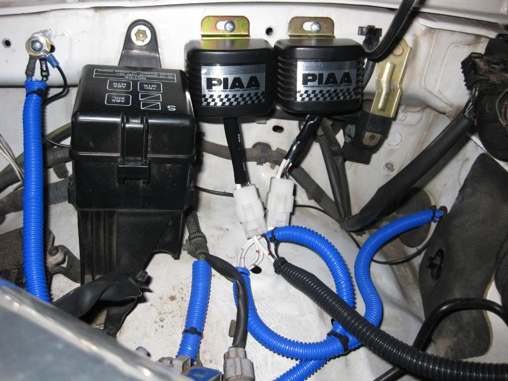
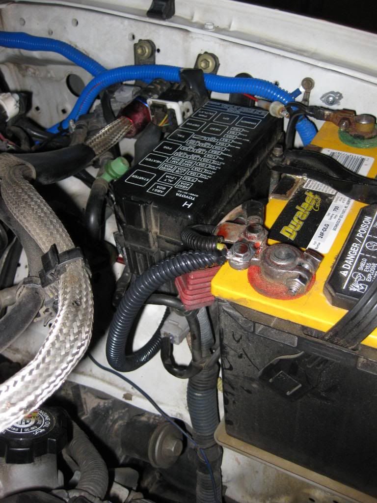
Then I soldered 2 of the power wires coming from the lights to each relay. I soldered the 2-12 gauge power relay wires together and ran 1 common 12 gauge wire toward the battery. I soldered the 2 light switch ground wires together and ran a single 16 gauge ground wire to the switch. I soldered the 2 light switch power wires together and ran a single 16 gauge power wire to the switch. I kept the common 12 gauge power wire, switch power wire, and ground wire all together and put them in some black conduit.
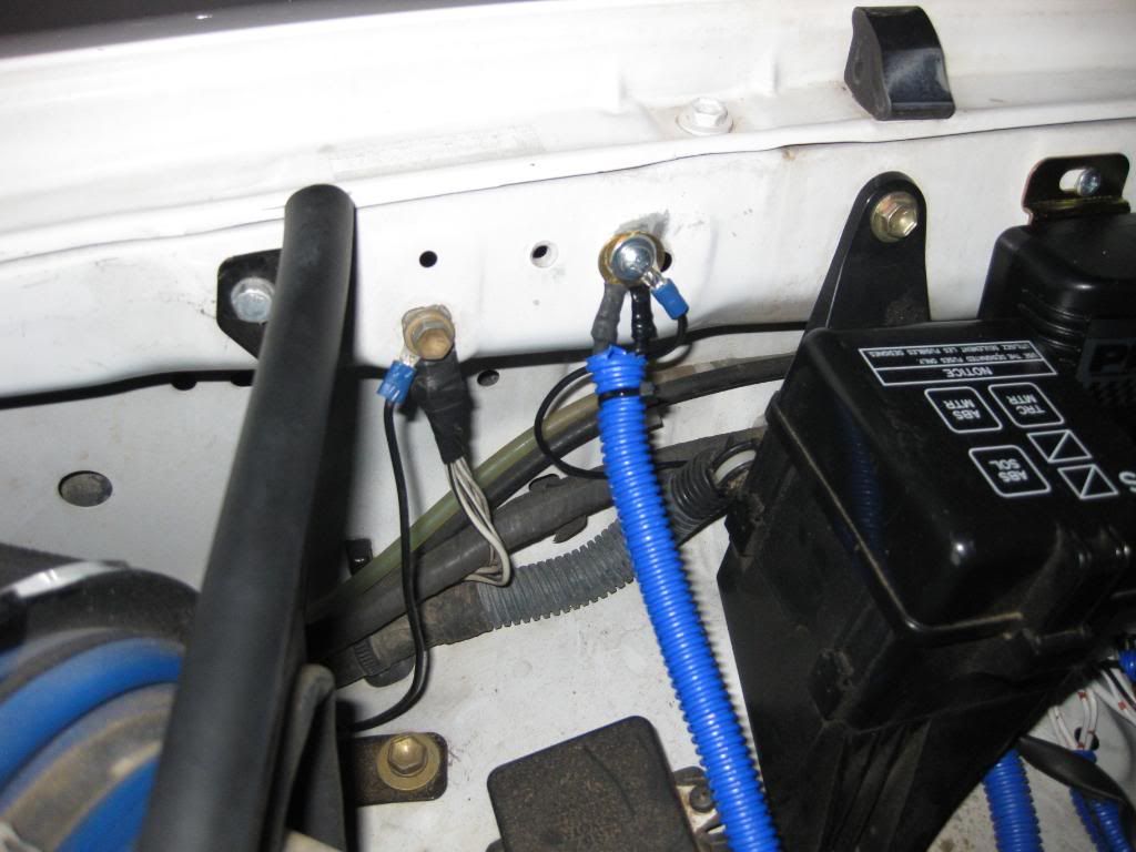
I soldered a new 16 gauge "light switch power wire" to the common 12 gauge power wire and ran the single 12 gauge power wire to the battery. I did it this way so I would only have one power wire connected to the battery, because I already have a couple of other wires connected to the battery and I wanted to keep it as clean as possible.
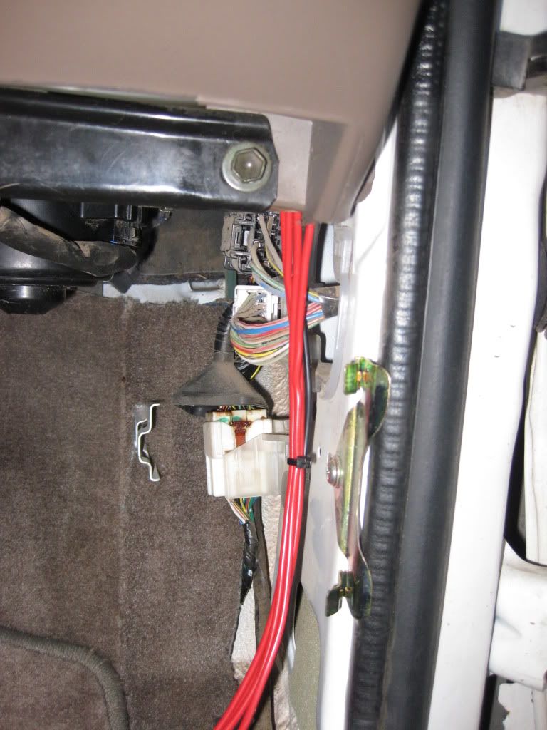
Finally, I ran the 3 light switch wires through an existing hole in the firewall and attached them to the switch.
Here is a wiring diagram that I put together for anyone interested in doing this project.
Fist I mounted the lights and modified the wiring harnesses for the PIAA's. I ended up cutting off the white male/female connectors for each light and soldered some 16 gauge wires to the ground and power wires for each light (red=power, black=ground). Then I wrapped the wires in some conduit to keep them organized and make the install look cleaner. I used zip ties to hold the wires/conduit to the rack.
Before running the wires down the roof and into the engine bay I did 2 things:
1) I soldered the 4 ground wires (1 from each light) together into one common 16 gauge ground wire.
2) I installed a Sure Seal Connector which allows me to quickly disconnect the lights so I can easily remove the rack if I want/need to. The Sure Seal Connector is great but keep in mind that you have to make the connector yourself. I purchased the connector and required pins from this website: http://www.peigenesis.com/ I went with a 5 pin connector (4 power wires, 1 common ground wire) and 10 pins and 10 sockets. I didn't need all the pins and sockets but I wanted to make sure that I had extras just in case I messed up when assempling the plug and pins. Also, you will need a pair of "open barrel crimping pliars" in order to properly attach the pins and receptacles to your wires. I couldn't find them at any local store so I ended up ordering mine from here: http://www.coolerguys.com/8405560926...hannelid=FROOG
The specific model numbers of Sure Seal materials I used are as follows:
Plug: 120-1841-000
Receptacle: 120-1839-000
Pins: 030-2196-000 (or 001)
Sockets: 031-1267-000 (or 001)
Then I ran some wires from the roof into the engine bay. I chose to run the wires down the passanger side A pillar because I already have a gauge pod on the driver side A pillar and I didn't want to have to run more wires down that way. I removed the end cap on the facory roof rails and pulled out the yellow plug. This is a perfect sized hole to run my 5-16 gauge wires. NOTE: Be sure to use some silicone sealant on the wires and the hole when you are done or you will have water seep through the headliner and into the cab!
In order to access the hole from the inside I just had to remove the 3 "oh s***" bars and some of the to trim pieces. Once the trim pieces were out of the way, it was pretty easy to run the wires down the A pillar.
Then I drilled a hole in the firewall to run the wires into the engine bay. Be sure to use a rubber gromet to prevent any water from coming into the cab from the engine bay.
Then I mounted the relays where I wanted them and attached the ground wires to the body using self-tapping screws.
Then I soldered 2 of the power wires coming from the lights to each relay. I soldered the 2-12 gauge power relay wires together and ran 1 common 12 gauge wire toward the battery. I soldered the 2 light switch ground wires together and ran a single 16 gauge ground wire to the switch. I soldered the 2 light switch power wires together and ran a single 16 gauge power wire to the switch. I kept the common 12 gauge power wire, switch power wire, and ground wire all together and put them in some black conduit.
I soldered a new 16 gauge "light switch power wire" to the common 12 gauge power wire and ran the single 12 gauge power wire to the battery. I did it this way so I would only have one power wire connected to the battery, because I already have a couple of other wires connected to the battery and I wanted to keep it as clean as possible.
Finally, I ran the 3 light switch wires through an existing hole in the firewall and attached them to the switch.
Last edited by 4ever4running; 02-25-2011 at 10:03 AM.
 02-25-2011, 11:33 AM
#18
 Haha the only way that I will take that front plate off is when I put a new one on that says "7 time super bowl champions". GO STEELERS!
 Thanks Mauzer! It took the better part of a weekend and 3-4 trips to the hardware store to get everything installed cleanly and the way that I wanted it so its nice to hear that all that work paid off.