Taurus Electric Fan mod on the Gen 3 4Runner
 07-09-2008, 07:28 AM
#1
Taurus Electric Fan mod on the Gen 3 4Runner
I completed my Taurus fan mod on my '98 Gen 3 and as promised, here is the write up. I still have a few more pics I want to include and may edit this post to incorporate them, but I wanted to get this up as quickly as I could.
I incorporated fan indicators that will come on when the fan is running so that installation is also included in the write up. I hope you all enjoy this. I am always open to suggestions, improvements, comments. Thanks to all of my fellow YTers for your encouragement.
its a long process so it is a long post!
Taurus Electric fan on Gen 3 4Runner
NOTE:
Disclaimer: As with all modifications, this write up is for educational purposes only. Any use or application of this procedure is done so at the risk of the installer/owner. The author and YotaTech are not responsible for any modifications done to any vehicle using these or any other related procedures contained in this write up. Descriptions and photographs are the sole property and copyright of the author and may not be copied or distributed without written consent. Links to this article may be allowed but are protected by all US copyrights. Use of specific products along with any photographs of such items remains the copyrighted property of the copyright holder and is not an endorsement of any specific company or items.
Some hand tools you will need:
3/8 drive ratchet
3” extention
6” extention
8, 10, 12, 13 mm sockets and wrenches
Diagonal cutters
Wire strippers
Crimper
Jig saw
Drill with various size bits
Utility knife
Bucket
Funnel
Channel lock pliers
As well as other assorted hand tools as required
Supplies:
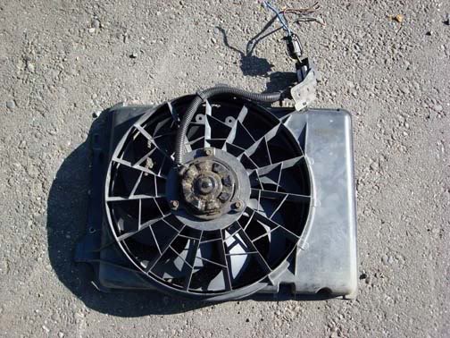
Taurus 2 speed electric fan
*Adjustable thermostat/controller TorqFlo p/n 733647 – LO speed
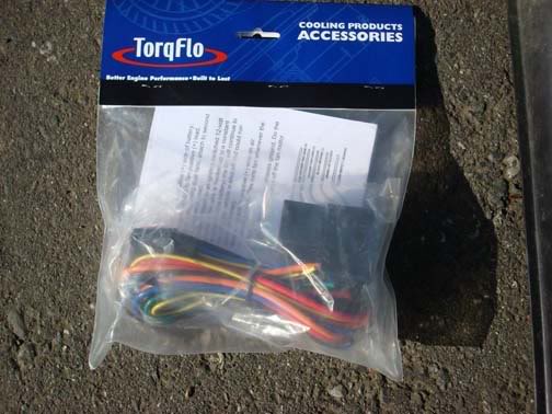
Single stage electric fan thermostat TorqFlo p/n 733652 – HI speed
(photo pending)
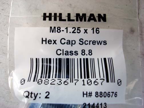
M8-1.25 x 12 or 16 metric bolts (4)
Washers (8-12) to fit the fan studs if you do not use the bolts
10 mm Bolts (3) for attaching the shroud to the fan
10 mm Washers (6) for attaching the shroud to the fan
Nylon wire ties – 6 & 10 inch
ABS type cement used for plumbing piping
(the black ABS cement may work better then the cream color General purpose ABS, PVC cement I used)
ABS cement cleaner
Split loom
Electrical tape
Loop connectors
Splice connectors 18 ga, 14-16 ga. 10-12 ga.
Blade connectors (12-10 ga., 14-16 ga. 18 ga.)
Bullet connectors 18 ga.
30 amp fuse
5 amp fuse
Green LED indicator Radio Shack p/n
Red LED indicator Radio Shack p/n
Wire of various sizes and colors:
12, 14 and 18 gauge
(I used wiring from an old harness so I could use similar colors for the wires from the switch, and relay controllers)
*I used two controllers; one for each speed and so one is thermo controlled the other is manual.
TorqFlo p/n 733647 Adjustable
TorqFlo p/n 733652 Single stage
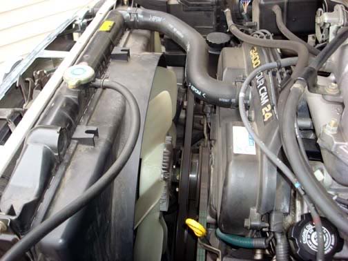
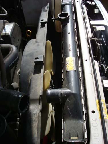
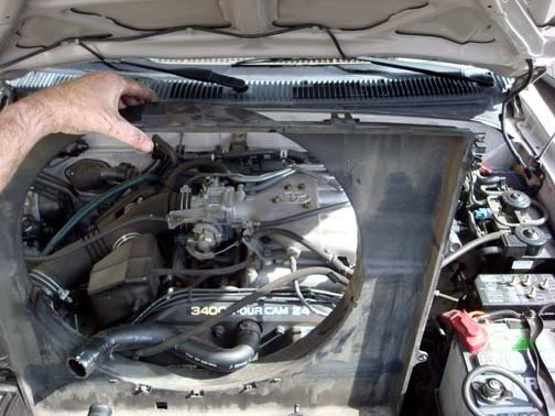
This is the engine bay before you begin.
Begin with dropping the skid plate. 5 – 12mm bolts
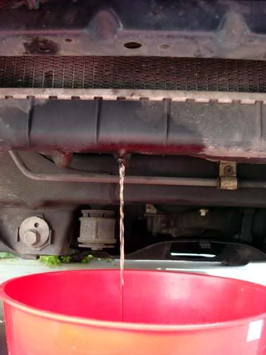
Using a suitable container, place it under the drain pet cock and open the valve. Remove the radiator cap and allow the system to drain.
Remove the upper hose clamp.
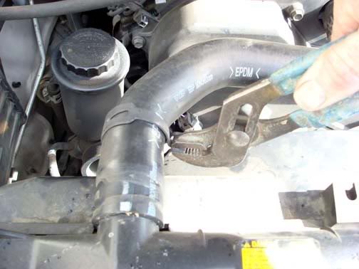
Remove radiator overflow tube from the radiator cap. This is a simple clamp wire that can be easily removed with your fingers or use a small set of pliers.
Remove the four (4) radiator 10 mm shroud bolts. Two on either side of the radiator.
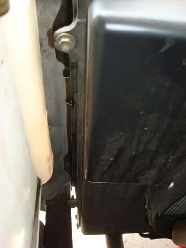
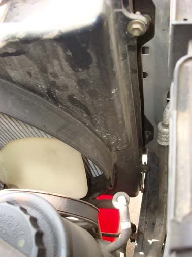
Push the loosened shroud towards the engine to allow room to get to the clutch fan.
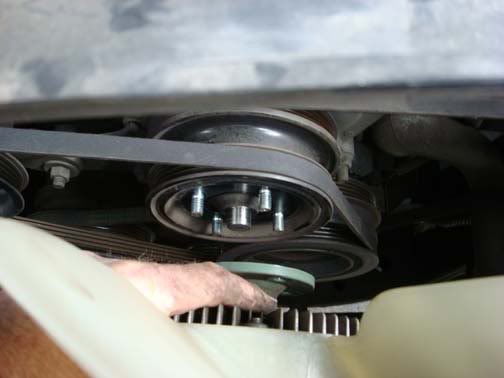
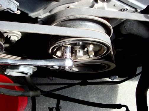
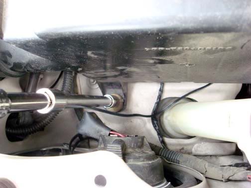
Remove the four (4) 12 mm clutch fan nuts that secure the clutch fan to the fan pully.
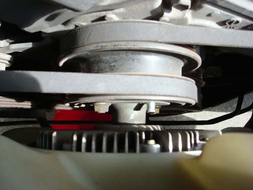
When the nuts have been removed, pull the fan clear of the engine compartment.
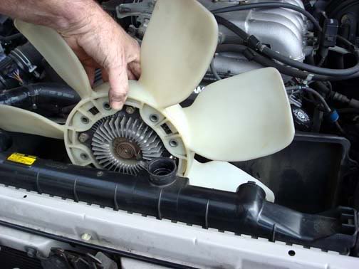
Remove the shroud.
NOTE: If your belts are in need of replacing, this would be a very good time to do so instead of installing the fan pulley nuts. You can wait and complete the radiator pulling steps before you complete the belt removal and subsequent installation. I mention this as you already have it torn apart. It will just save you some maintenance time later
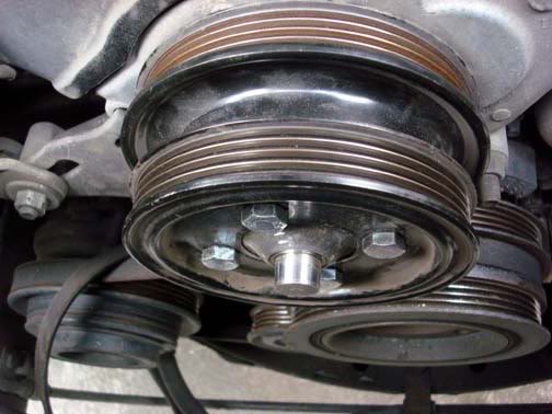
If you intend on using the installed fan pulley threaded studs, install at least 3 flat washers on each stud then install the fan pulley nuts. And tighten.
Remove the lower radiator hose.
If you have not already removed the front grill, do so now.
Remove the four (4) radiator securing bolts. These are accessed from the front of the radiator.
Pull the radiator directly upward and remove from the engine compartment
With the radiator removed you now have ample room to work on removal and replacement of belts.
NOTE: If you need or desire better clearance between the engine shaft of the fan pulley and the electric fan motor in the new radiator shroud, replacing the studs with metric bolts is optimal. I made the mistake of not installing washers on the fan pulley studs and when I tightened the nuts they seemed to be tight but were actually tightened on the end threads of the studs. When I discovered this error, I attempted to remove the studs and they pulled out.
Remove the studs with vise grip or channel lock pliers.
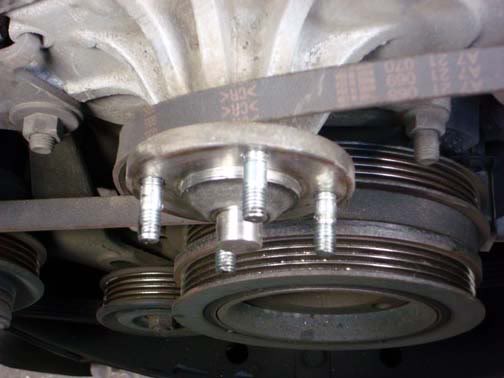
With the studs removed, install four (4) M8-1.25 12 or 16 mm bolts
If you desire to replace your drive belts do so at this time.
Fitting the Taurus fan to our OEM Toyota fan shroud.:guitar
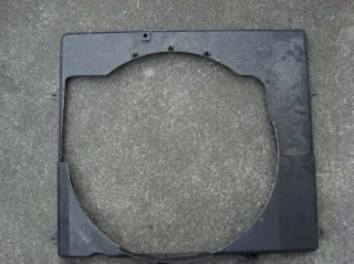
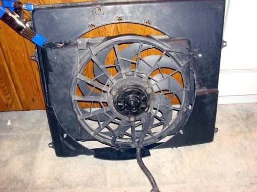
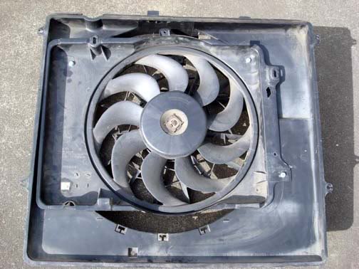
Unlike the installation into a Gen 2 4Runner, the OEM shroud for the 3.4 V6 is considerably larger and as such is not as easy a direct bolt in. As can be seen in the picture, the OEM shroud is much larger. Therefore, to use the Taurus fan some cutting to the Gen 3 shroud will need to be done in order to utilize the radiator coverage that the OEM shroud affords.
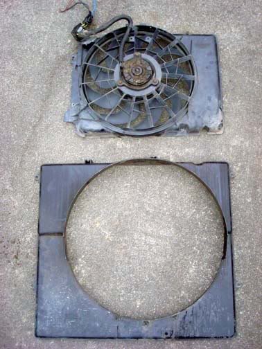
Begin by placing the fan on the ground and lay the shroud over it to begin to see what the optimum center is located.
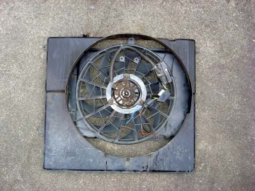
I attempted to place the fan so that it can utilize the contour of the shroud while still remaining flat or flush with the radiator fins. This did prove to be a bit of a challenge. The fan needed to be some what against the shroud for mounting as well as to provide for maximum air draw from all parts of the radiator but also not to be too far back so as to impinge on the fan pulley once installed.
Initially I attempted to mount the fan totally using � 20 bolts and washers. This proved to not be a desirable solution so cutting of the shroud will be involved.
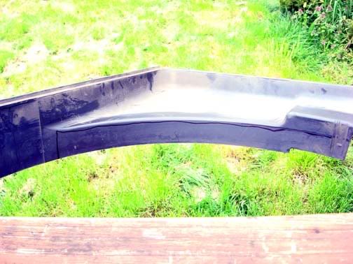
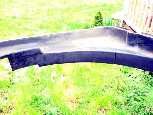
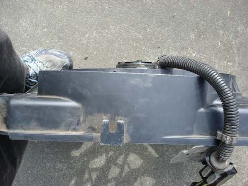
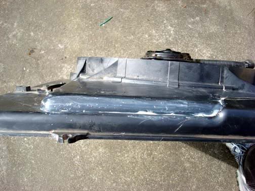
Note: The next portion of the cutting of the OEM shroud is not mandatory but can be accomplished if desired. At first I thought I would need to remove a portion of the OEM shroud rear extended edge, but after final fitment and gluing I discovered that removal of this material was not needed. If you desire to do so then I provide the pictures for your evaluation.
Mark and remove the following portions of the shroud:
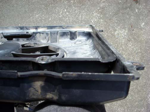
Both lower corners will require that you mark the location of the Fan in the shroud in order to allow the fan to “fit” into the lower portion of the shroud. When you mark these for cutting be sure to remember that you do not need to remove so much that the flange on the taurus fan is still inside the OEM shroud. This will allow the fan to fit more flush against the radiator due to the change in levels of the OEM shroud.
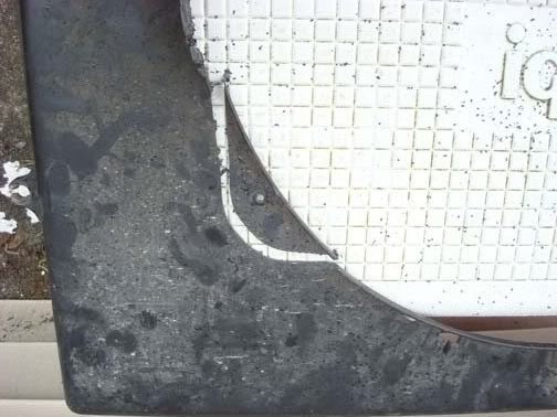
After removal of the corner material check the fit again to ensure the fan will be nearly flush in the shroud.
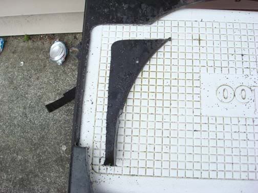
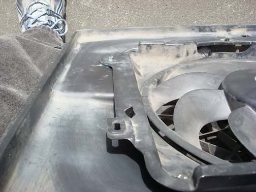
You will notice that you will need to cut two notches in the lower right corner to accommodate the fan support braces moulded into the Taurus shroud. Mark the location and use the jig saw to cut the notches.
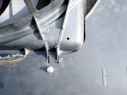
When you are satisfied with the location of the fan, drill a hole at each of three corners as shown to provide for attachment of the fan and OEM shroud.
Using a large clamp, position the fan in the lower large cutout to check for fitment and to see if it is flush.
This is in preparation for gluing the larger cutout in the OEM shroud to the Taurus fan. There are some other options but I felt that gluing this corner was the best method of securing this large corner.
Check your position and fitment.
Glue the large cutout in place. I tried several different types of glue. First I tried an epoxy made for plastic but after setting, the glue did not adhere very well to the fan and shroud. When the fan was set down on the ground, the shock of contact with the ground, minor as it was caused the epoxy to release. Next was ABS plastic pipe cement. There are several types available. I chose the General cement. It comes in a red can and is cream colored. Used with the recommended plastic cleaner which is in a yellow can. This can be obtained in most any hardware store such as Home Depot or Lowes. Another option is the standard ABS cement that is black in color. I was not sure when I looked at these cements as I was not sure if the standard ABS cement would be too hot for the plastic. It is worth investigating as it may be a better solution and it would match the color of our fan and shroud.
Liberally use the cement along the seams. There will be a slight gap along this cutout and the fan itself so use enough to provide for a fill. Allow this to remain undisturbed for at least 12 hours.

Once the glue has cured, you will have your completed fan ready for installation into the engine bay.
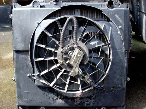
One thing I noted during fitup in the engine bay was that I was in need of a bit more clearance between the fan motor housing and the fan pulley. I obtained the needed clearance by placing 2-3 additional washers between the OEM shroud and the fan housing at the two bolts on the left side of the fan. This pulled the fan forward slightly into the shroud towards the radiator providing additional clearance of about 1/4". Check your fitment and determine if you need to add these extra washers.
Installation in the Engine Bay
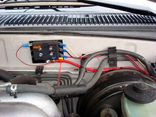
Begin by prepping the installation area. I would like to recommend that you consider adding the Auxillary Fuse panel if you have not already installed it. There are several excellent articles on installation. I installed one in my engine compartment on the firewall and it is excellent for providing you with the contact points for power for running all sorts of various accessories. If you intend on doing any accessory lighting such as fog or driving lights, additional 12vdc outlets or supplying power for a power amp for your sound system, I can not begin to recommend this mod enough. All power needs for this mod are supplied from my Aux Fuse panel. This installation refers to the Aux Fuse Panel for hookup. Here is where mine is installed. This will provide all the power needs for the fan and relays.
One thing that will aid in the installation of the wiring, installation of the relays and hook up of the fan itself is to remove the air box.
This next step is for 96-98 4Runners with stock air intakes. Remove the connector from the MAF sensor.
Grasp the top of the connector and squeeze the tab. Pull the connector out of the MAF.
Remove the two bolts at the base of the MAF.
Remove 3 bolts holding the air box in place. The one located on the radiator cross support piece will be completely removed while the ones located on the fender, one front and one rear of the air box are captive bolts. Just loosen them completely.
Pull the MAF from the rear of the air box back and upwards.
Pull the air box out of the fender towards the engine and when free of the fender opening, pull the air box out of the engine bay and set aside.
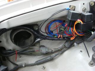
On the right side fender you will note several factory accessory attachment points.
I chose these two with OEM installed nuts as the attachment points for the relays. These provided two major advantages.
1) Ready made solid attachment points requiring no drilling.
2) Easy access to the temperature adjusting set screw on the LO speed relay.
Using 10 mm bolts, attach the relays to the fender well.
I would recommend now that you remove the bolts that secure several components along the fender towards the firewall to aid in routing the wires necessary to power the fans and relays.
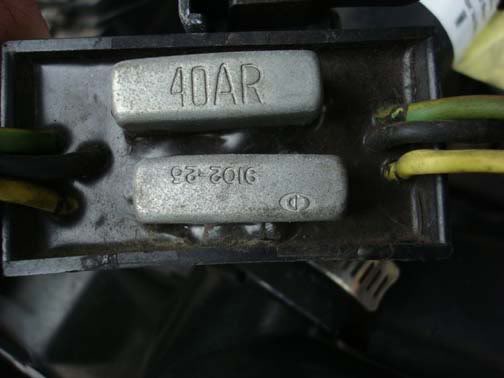
The Taurus fan I obtained was from a 1995 sedan with the 3.8 V6. While it may not be necessary, I obtained the entire cable for the fan. This included a rather unusual looking connection that the fan plugged into. I was never able to find out just what this connection does but I did discover that 1995 was the only year they installed this “control relay/fuse” connector. The Ford dealer could not explain its specific purpose but there had been issues with this fan set upin the previous years of Taurus. The determined this "control box" was critical to proper operation. The electrical diagrams for the car did not show them in the circuit, but the part was over $100, I figured, some engineer thought it was a good idea so I kept mine and installed it.
There are three (3) wires.
Blue – HI speed
Brown/Yellow – LO speed
Black – Ground for both fan speeds.
When I removed my fan from the donor vehicle, the Brown/yellow wires actually were two smaller wires spliced into a single larger gauge wire coming out of the connector. When I spliced the LO speed control wire from the control relay, I spliced in both the wires instead of cutting them near the factory splice at the larger gauge wire. This facilitated not having to either add wire to the relay wires or cut the other relay connections shorter. It just gave me more wire to work with.
The colors change coming out of the connectors to the box, then change back leaving the other side connector.
If you use this fan from a different year Taurus/Sable or Lincoln this connection may not be there. So to simplify the installation I just mounted the fan relay box to the radiator shroud.
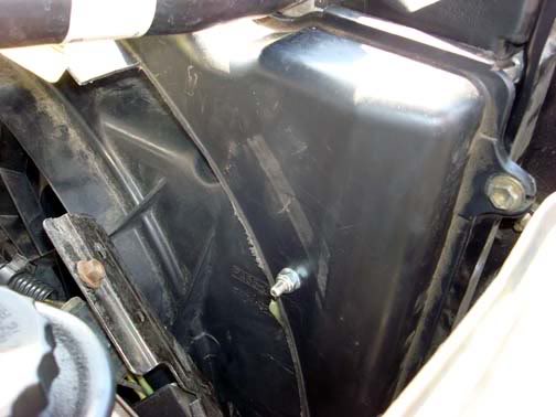
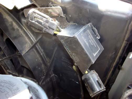
It required drilling a hole in the shroud near the top. I had removed some of the shroud trailing edge material during my shroud modification so it made the placement very easy. If you do not remove this edge material you may need to modify where you place the fan box. My location followed the contour of the fan and direction of the mounting plate and wires. This also provided for easy attachment/splicing of the wires from the fan to the control relays.
Fan control
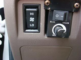
While it is not necessary to provide for dual control of this 2 speed fan, it is very practical. Any two or three position switch can provide you with the degree of control you desire. I chose to use a three position switch, ON-OFF-ON rocker switch. Having the two ON positions allow for control of the two speeds, one in thermostatic control, the other full manual control.
LO is wired in so that the thermostat controlled relay will operate the fan slow speed as required by engine temperature demands. HI is a full manual control which cuts the power to the slow speed of the fan while energizing the high speed setting independently. Selecting the OFF position removes power from both settings which can be useful in water crossings preventing water from splashing into the fan blades while they are moving which has been known to damage the plastic fan blades. Just another added bonus of this installation.
My choice of switch was an OEM rear heater fan speed selector switch from the center console of a 4runner. Choosing this switch allowed me the ease of installation into my driver’s dash and it is already marked as a fan! While I did have to modify the switch for proper operation, it is a very simple switch mod that requires minimal soldering skills. This fan switch can be acquired from almost any year 4runner and costs anywhere from free to less then $10.
If you chose this switch for your fan control, I would recommend that you also get not just the switch, but get both halves for a complete connector from the console that it plugs into. This provides the ability to remove the switch for either replacement or repair. Also you will be able to disconnect the switch if you need to remove the lower dash panel.
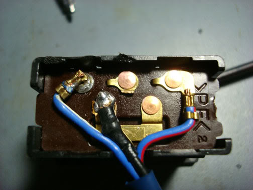
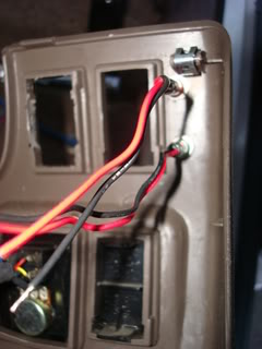
This is the switch as Toyota configured it for use in the rear heater speed select.
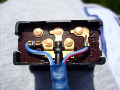
You will note the three (3) wires coming from the switch.
Blue/white – LO speed select (left side)
Black – common for both speeds (center)
Blue/red – HI speed (right side)
NOTE: I initially moved the blue/white from the common bus bar at the center/bottom of the switch to the upper left corner (see diagram) but found out the way the switch is internally set up this would not work correctly for our application. Eventually I had to move the black center contact to the lower bus bar. This would later be used as 12vdc input to the switch. While this made for easier identification of wiring, it involved a second wire removal and solder. If you don’t mind doing this, then you can do as I did. In hind sight, I would have left the wires configured and move only the black from center top to let top leaving the bus bar with the blue/white wire. You just have to remember the colors of the wires as you go to make this simpler.
Using a small pair of needle nose pliers, grasp the Blue/white wire near the contact. Move this up and down until the contact breaks free. Using some solder and flux, clean and solder the separated contact to the upper most left contact.
Check continuity using a multi-meter in both LO and HI switch positions and no continuity when the switch is in OFF.
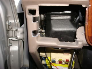
Route the switch wire through the lower dash panel opening provided for a Toyota switch and connector.
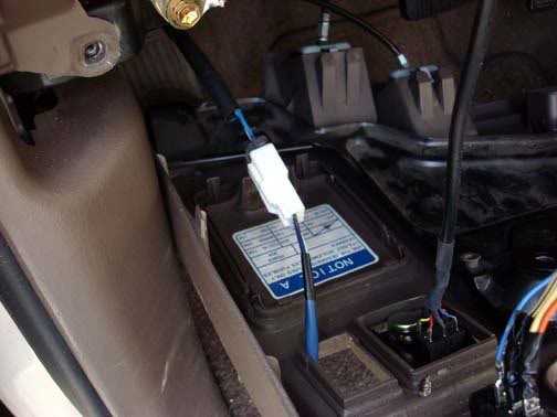
Using a pull wire, push the pull wire through the drivers side wire boot on the engine side of the firewall into the passenger compartment.
Attach the wires from the switch to the end of the pull wire with tape. If you are planning to use LED indicators for fan operation, also route a control wire for the LO speed switch position along with the 3 other switch wires.
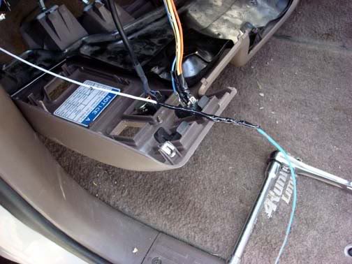
Pull the wires through the firewall into the engine compartment.
Now we are ready to begin wiring up the fan and switch control to the relays.
Note: I used TorqFlo brand Adjustable Electric Fan Thermostat p/n 733647 for the LO speed and Single Stage Electric Fan Thermostat p/n 733652 for the manual HI speed. My directions are for these two relay controllers. If you use a different brand, follow your installation instructions in conjunction with this setup.
Once again identify the wires from the fan control switch. There are three wires. From the switch to the connector:
Black – 12vdc
Blue/White – LO speed
Blue/Red – HI speed
From the connector to the engine compartment:
Blue/Green – 12vdc
Blue/White – LO speed
Blue/Orange – HI speed
NOTE: When selecting, and then attaching the wires described, do NOT install any fuses at this time.
If the wire from the switch connector is not long enough to reach the Aux Fuse panel, route additional 16-18 gauge wire from the connector to reach the Aux fuse panel. Select an available contact location and crimp a female blade connector to the wire. Attach to the male blade connector on the fuse panel. Splice the other end to the 12 vdc wire from the switch. This is the source 12 vdc to operate the relays( LO or HI ).
Route two switch control wires to the right side of the vehicle to the relays. Identify which wire is for the LO speed relay and which one will be for the HI speed relay. Splice the two control wires (LO & HI) to their applicable wire from the switch connector in the engine bay.
Route a single 14 gauge wire from another available location on the accessory fuse panel to the relays until it is approximately 6 inches from the relays. I used red wire to correspond to the red wires on the relays. You will then add a second wire near the relays via a crimp. This is going to be the primary power inputs for the two fan speeds via the relay contacts. As this fan is only operating one speed at a time, this setup will save on wires and connections. Crimp a female blade connector and attach to an available connection on the Aux Fuse panel.
If you desire to install LED monitor indicators for fan operation, you will need to route a single 18 gauge wire from the switch location on the dash to the relays. I used a similar color coded wire from a salvaged wire harness (red/orange). This will connect to the output of the LO speed relay control power to the positive lead of the LED located next to the fan switch. When the fan runs, it will then light the indicator notifying you that the fan is in operation. This is only required for the LO speed only. The indicator for the HI speed is connected at the switch on the dash.
Install split loom around the wires that you routed from the fire wall and from the fuse panel to the relays. This provides for secure routing and protection for the wires. Tie wrap as necessary to secure the split loom in position.
Connecting the relays
Connect the Red 12 vdc wire from the Aux Fuse panel to the red leads of the two relays. This is your battery supplied power that operates the fan motor (30 amp)
Connect the LO switch wire to Yellow ignition source wire of the adjustable relay
Connect the HI switch wire to the Green wire of the Single stage relay. Normally the green wire would be for connection to the AC clutch. As the HI speed is our manually controlled fan speed, connecting to the green wire gives us direct switching control of the single stage relay.
These two wires (Yellow for the adjustable and Green for the single stage) provide relay operating power to close the relay contacts that then route our high current battery power to the operate the applicable fan speed.
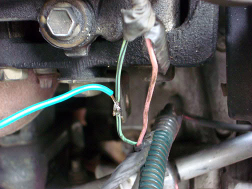
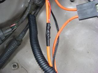
Connect the green output wire of the adjustable relay to the AC clutch wire. This wire is located on top of the AC compressor on the right side of the engine near the front. The wire from the AC clutch is located in a green split loom.
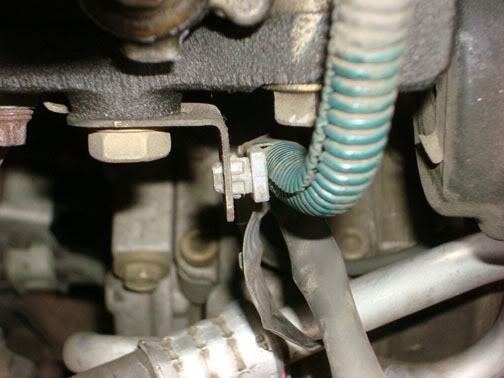
Remove the tape covering the two wires. The wire we will splice into is green/black
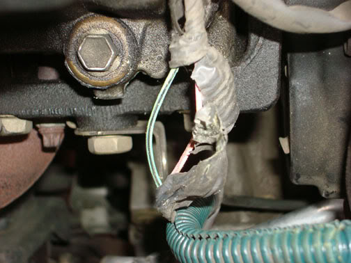
You can either use a splice connector or solder the wires. I stripped the insulation and soldered mine. Use electrical tape and seal the splice, insert back into split loom.
Combine the two black leads from the relays and crimp to a single loop end. Remove one of the relay mounting bolts, locate the loop end behind the relay and attach the bolt. This is the ground wire for the relays.
Route the orange power out wires from the relays along the right fender well across the radiator support to the fan speed wires. Locate the fan speed ground wire (black). Crimp a loop end connector large enough to accept the top radiator mounting bolt. Mount loop to bolt and tighten.
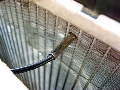
Route the temperature sensor wire and probe to the right side of the radiator. Choose a location near the upper hose water inlet. Use a small instrument like a pencil to open the fins slightly. Insert the probe into the radiator fins. Do not insert the probe into the fins so the probe extends past the radiator core. The probe should fit tightly. If the probe is not tight, use a small amount of JB QuikWeld to hold the probe in position. Only a very small amount is required to hold the probe properly. You do not want to clog the cooling fins.
Identify which wire is for the HI and LO speed of the fan. This can be accomplished by connecting the selected lead to the positive terminal of the battery with the ground connected and this will run the fan in the selected speed. Note which color wire is for which speed then connect the applicable wire to the either the LO or HI speed power wire coming from the relays as applicable.
If you routed the indicator wire for the LO speed, connect this indicator wire to the LO speed orange wire coming out of the adjustable relay.
NOTE: I had already installed the wires previously so I needed to strip insulation as I installed my indicator wire after the install had been completed.
If desired, you can splice using an appropriate size crimp or solder the indicator wire after stripping insulation.
Cut the indicator wire to length.
Solder the indicator wire to the fan power wire.
Use electrical tape and seal the splice.
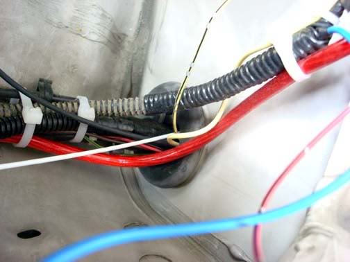
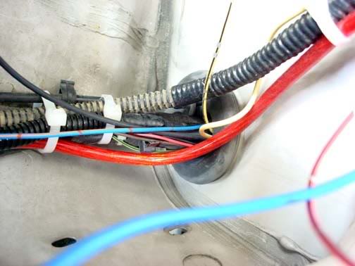
Use split loom to enclose the wires from the fan to the relays. Use electrical tape as required to seal the ends of the split loom. Route the new cable along the inside of the radiator support, to the fender well going above the air box opening in the fender well. Use nylon tie wraps to secure the cable along the route. The Blue relay leads will not be used in this application so coil them up and secure to the fender well.
If you are not installing indicators for the fan speeds, verify your connections, ensure the switch is installed. Insert blade type fuses in the Aux fuse panel, 30 amp for the Fan supply, 5 amp in the switch connection position.
If you are installing Fan speed indicators I recommend the following ready made LED from Radio Shack.
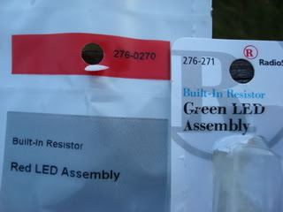
After obtaining your indicators, continue as follows:
If the lower dash panel is installed remove the four 10 mm bolts securing the lower dash panel. The Fan Speed selector switch should be located in the lower row left most location.
Select the position for the LED indicators. Using 9/32” drill bit, drill out the mount positions.
Position the lower dash panel in its location, using a sharpie marker, mark the hole locations for the LED indicators in the mount/support for the dash.
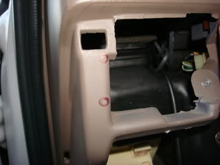
Using a utility knife, cut out the area around the marked locations for the indicators. The housings for the LED indicators will fit into these cut outs. Be careful not to cut out too large of pieces. Remove the scrap plastic pieces.
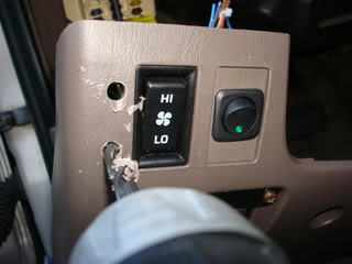
Install the LED indicators in the lower dash panel. This is the view from the rear side.
Connecting up the HI side to the indicator uses a pick off point near the switch. Select a location about � way down the switch cable. Cut the sleeve exposing the 3 wires.
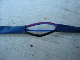
Locate the blue/red wire. Splice in a length of wire approximately 6” long. This will be the tap in for the HI speed indicator.
Install bullet connectors on each end of the black leads from the LEDs. Install the matching bullet connectors on two short pieces of wire approximately 3” long. Combine these two leads to a loop connector for attachment to a common ground point.
Using bullet connectors, connect the LO wire (blue/white) to the LED red lead wire designated for LO switch position. Connect the HI wire (blue/red) to the LED red lead wire designated for the HI switch position. Plug these connectors together These connectors will enable removal of the switch and lower panel along with the LEDs in the event of a failure or removal of the lower dash panel.
Reassemble the lower dash panel. Start the vehicle and test the switch positions. With the LO switch position selected, engine running at idle, operate the AC and verify the LO speed fan starts and you have a corresponding indication of operation.
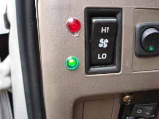
Turn off the AC and then shift the selector switch to HI. Verify the high speed fan comes on and you have a corresponding indication.
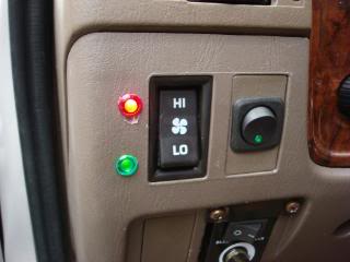
NOTE: Due to the configuration when the HI position is selected, you should have both indicators operating. The LO speed coils will act as a generator sending a voltage back to the LO indicator resulting in both indicators illuminating. Also if the LO speed switch position is selected (normal operations) if air is entering the radiator at freeway speeds the fan will auto rotate illuminating the indicator, but it may be at about � illumination.
Adjustment of the Thermostat
After all tests have been completed, allow the vehicle to reach normal operating temperature. If the fan energizes before or at the correct operating temperature, some adjustment of the thermostat will be required. Toyota recommends operating temperature of around 185 degrees. The TorqFlo adjustable thermostat is factory set for 160 degrees. To adjust the thermostat, locate the adjustment potentiometer. This is a small blue box with a yellow adjustment screw in the center

NOTE: Adjustment range is only � of a turn. DO NOT force the screw past the stop point.
To increase the temperature the fan will turn on at rotate the set screw clockwise
To lower the temperature, turn the set screw counter-clockwise.
I drove my truck for about 10-15 minutes then adjusted the potentiometer so the fan would just come on. Then adjusted it backwards so it just shut off. This should set the fan turn on point at about 3-5 degrees above normal operating temperature. After I had everything installed and operating, I took my truck to the Toyota dealer and asked the mechanics there to do a thermo check for me. They read 146 degrees at the center of my radiator (no fan running). Then when I shifted the manual override to HI the temperature began to drop within about 10 seconds. After 30 seconds the temp had dropped 10 degrees.
At this setting I have only had a few times that my fan would come on after shutting down my truck. If this is an issue, or you encounter this as a common occurrence, you can readjust the settings for the turn on point. I would not recommend turning the switch to the OFF position as you may forget to turn it back on when driving again. If anyone has a suggestion for installation of an indicator that would come on at ignition, I am welcome to your suggestions. Please PM or email me directly.
I incorporated fan indicators that will come on when the fan is running so that installation is also included in the write up. I hope you all enjoy this. I am always open to suggestions, improvements, comments. Thanks to all of my fellow YTers for your encouragement.
its a long process so it is a long post!
Taurus Electric fan on Gen 3 4Runner
NOTE:
Disclaimer: As with all modifications, this write up is for educational purposes only. Any use or application of this procedure is done so at the risk of the installer/owner. The author and YotaTech are not responsible for any modifications done to any vehicle using these or any other related procedures contained in this write up. Descriptions and photographs are the sole property and copyright of the author and may not be copied or distributed without written consent. Links to this article may be allowed but are protected by all US copyrights. Use of specific products along with any photographs of such items remains the copyrighted property of the copyright holder and is not an endorsement of any specific company or items.
Some hand tools you will need:
3/8 drive ratchet
3” extention
6” extention
8, 10, 12, 13 mm sockets and wrenches
Diagonal cutters
Wire strippers
Crimper
Jig saw
Drill with various size bits
Utility knife
Bucket
Funnel
Channel lock pliers
As well as other assorted hand tools as required
Supplies:
Taurus 2 speed electric fan
*Adjustable thermostat/controller TorqFlo p/n 733647 – LO speed
Single stage electric fan thermostat TorqFlo p/n 733652 – HI speed
(photo pending)
M8-1.25 x 12 or 16 metric bolts (4)
Washers (8-12) to fit the fan studs if you do not use the bolts
10 mm Bolts (3) for attaching the shroud to the fan
10 mm Washers (6) for attaching the shroud to the fan
Nylon wire ties – 6 & 10 inch
ABS type cement used for plumbing piping
(the black ABS cement may work better then the cream color General purpose ABS, PVC cement I used)
ABS cement cleaner
Split loom
Electrical tape
Loop connectors
Splice connectors 18 ga, 14-16 ga. 10-12 ga.
Blade connectors (12-10 ga., 14-16 ga. 18 ga.)
Bullet connectors 18 ga.
30 amp fuse
5 amp fuse
Green LED indicator Radio Shack p/n
Red LED indicator Radio Shack p/n
Wire of various sizes and colors:
12, 14 and 18 gauge
(I used wiring from an old harness so I could use similar colors for the wires from the switch, and relay controllers)
*I used two controllers; one for each speed and so one is thermo controlled the other is manual.
TorqFlo p/n 733647 Adjustable
TorqFlo p/n 733652 Single stage
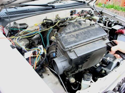
This is the engine bay before you begin.
Begin with dropping the skid plate. 5 – 12mm bolts
Using a suitable container, place it under the drain pet cock and open the valve. Remove the radiator cap and allow the system to drain.
Remove the upper hose clamp.
Remove radiator overflow tube from the radiator cap. This is a simple clamp wire that can be easily removed with your fingers or use a small set of pliers.
Remove the four (4) radiator 10 mm shroud bolts. Two on either side of the radiator.
Push the loosened shroud towards the engine to allow room to get to the clutch fan.
Remove the four (4) 12 mm clutch fan nuts that secure the clutch fan to the fan pully.
When the nuts have been removed, pull the fan clear of the engine compartment.
Remove the shroud.
NOTE: If your belts are in need of replacing, this would be a very good time to do so instead of installing the fan pulley nuts. You can wait and complete the radiator pulling steps before you complete the belt removal and subsequent installation. I mention this as you already have it torn apart. It will just save you some maintenance time later
If you intend on using the installed fan pulley threaded studs, install at least 3 flat washers on each stud then install the fan pulley nuts. And tighten.
Remove the lower radiator hose.
If you have not already removed the front grill, do so now.
Remove the four (4) radiator securing bolts. These are accessed from the front of the radiator.
Pull the radiator directly upward and remove from the engine compartment
With the radiator removed you now have ample room to work on removal and replacement of belts.
NOTE: If you need or desire better clearance between the engine shaft of the fan pulley and the electric fan motor in the new radiator shroud, replacing the studs with metric bolts is optimal. I made the mistake of not installing washers on the fan pulley studs and when I tightened the nuts they seemed to be tight but were actually tightened on the end threads of the studs. When I discovered this error, I attempted to remove the studs and they pulled out.
Remove the studs with vise grip or channel lock pliers.
With the studs removed, install four (4) M8-1.25 12 or 16 mm bolts
If you desire to replace your drive belts do so at this time.
Fitting the Taurus fan to our OEM Toyota fan shroud.:guitar
Unlike the installation into a Gen 2 4Runner, the OEM shroud for the 3.4 V6 is considerably larger and as such is not as easy a direct bolt in. As can be seen in the picture, the OEM shroud is much larger. Therefore, to use the Taurus fan some cutting to the Gen 3 shroud will need to be done in order to utilize the radiator coverage that the OEM shroud affords.
Begin by placing the fan on the ground and lay the shroud over it to begin to see what the optimum center is located.
I attempted to place the fan so that it can utilize the contour of the shroud while still remaining flat or flush with the radiator fins. This did prove to be a bit of a challenge. The fan needed to be some what against the shroud for mounting as well as to provide for maximum air draw from all parts of the radiator but also not to be too far back so as to impinge on the fan pulley once installed.
Initially I attempted to mount the fan totally using � 20 bolts and washers. This proved to not be a desirable solution so cutting of the shroud will be involved.
Note: The next portion of the cutting of the OEM shroud is not mandatory but can be accomplished if desired. At first I thought I would need to remove a portion of the OEM shroud rear extended edge, but after final fitment and gluing I discovered that removal of this material was not needed. If you desire to do so then I provide the pictures for your evaluation.
Mark and remove the following portions of the shroud:
Both lower corners will require that you mark the location of the Fan in the shroud in order to allow the fan to “fit” into the lower portion of the shroud. When you mark these for cutting be sure to remember that you do not need to remove so much that the flange on the taurus fan is still inside the OEM shroud. This will allow the fan to fit more flush against the radiator due to the change in levels of the OEM shroud.
After removal of the corner material check the fit again to ensure the fan will be nearly flush in the shroud.
You will notice that you will need to cut two notches in the lower right corner to accommodate the fan support braces moulded into the Taurus shroud. Mark the location and use the jig saw to cut the notches.
When you are satisfied with the location of the fan, drill a hole at each of three corners as shown to provide for attachment of the fan and OEM shroud.
Using a large clamp, position the fan in the lower large cutout to check for fitment and to see if it is flush.
This is in preparation for gluing the larger cutout in the OEM shroud to the Taurus fan. There are some other options but I felt that gluing this corner was the best method of securing this large corner.
Check your position and fitment.
Glue the large cutout in place. I tried several different types of glue. First I tried an epoxy made for plastic but after setting, the glue did not adhere very well to the fan and shroud. When the fan was set down on the ground, the shock of contact with the ground, minor as it was caused the epoxy to release. Next was ABS plastic pipe cement. There are several types available. I chose the General cement. It comes in a red can and is cream colored. Used with the recommended plastic cleaner which is in a yellow can. This can be obtained in most any hardware store such as Home Depot or Lowes. Another option is the standard ABS cement that is black in color. I was not sure when I looked at these cements as I was not sure if the standard ABS cement would be too hot for the plastic. It is worth investigating as it may be a better solution and it would match the color of our fan and shroud.
Liberally use the cement along the seams. There will be a slight gap along this cutout and the fan itself so use enough to provide for a fill. Allow this to remain undisturbed for at least 12 hours.
Once the glue has cured, you will have your completed fan ready for installation into the engine bay.
One thing I noted during fitup in the engine bay was that I was in need of a bit more clearance between the fan motor housing and the fan pulley. I obtained the needed clearance by placing 2-3 additional washers between the OEM shroud and the fan housing at the two bolts on the left side of the fan. This pulled the fan forward slightly into the shroud towards the radiator providing additional clearance of about 1/4". Check your fitment and determine if you need to add these extra washers.
Installation in the Engine Bay
Begin by prepping the installation area. I would like to recommend that you consider adding the Auxillary Fuse panel if you have not already installed it. There are several excellent articles on installation. I installed one in my engine compartment on the firewall and it is excellent for providing you with the contact points for power for running all sorts of various accessories. If you intend on doing any accessory lighting such as fog or driving lights, additional 12vdc outlets or supplying power for a power amp for your sound system, I can not begin to recommend this mod enough. All power needs for this mod are supplied from my Aux Fuse panel. This installation refers to the Aux Fuse Panel for hookup. Here is where mine is installed. This will provide all the power needs for the fan and relays.
One thing that will aid in the installation of the wiring, installation of the relays and hook up of the fan itself is to remove the air box.
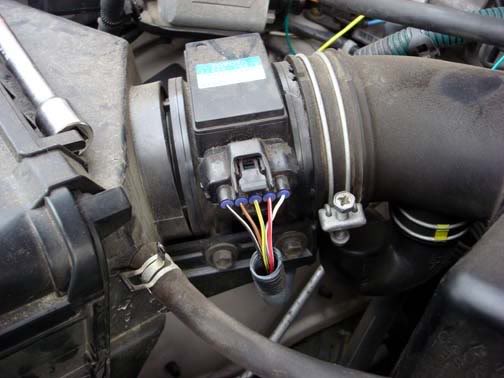
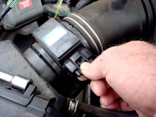
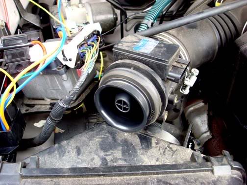
This next step is for 96-98 4Runners with stock air intakes. Remove the connector from the MAF sensor.
Grasp the top of the connector and squeeze the tab. Pull the connector out of the MAF.
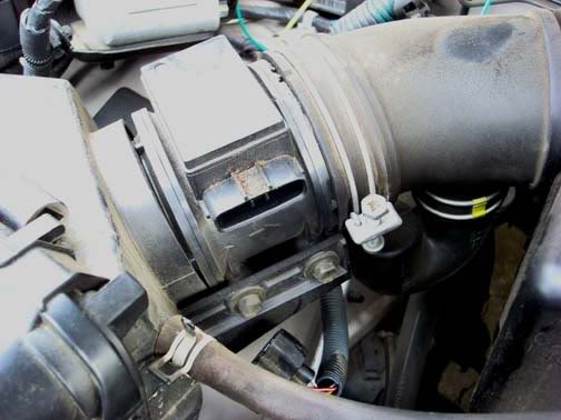
Remove the two bolts at the base of the MAF.
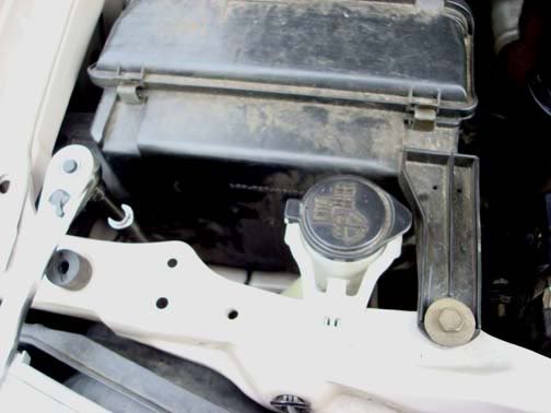
Remove 3 bolts holding the air box in place. The one located on the radiator cross support piece will be completely removed while the ones located on the fender, one front and one rear of the air box are captive bolts. Just loosen them completely.
Pull the MAF from the rear of the air box back and upwards.
Pull the air box out of the fender towards the engine and when free of the fender opening, pull the air box out of the engine bay and set aside.
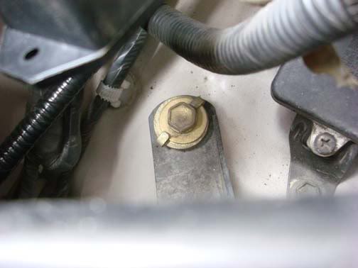
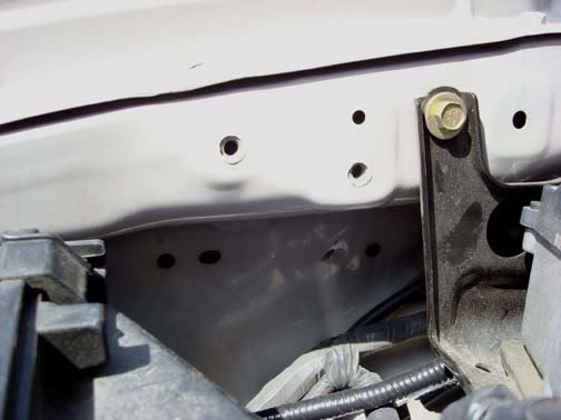
On the right side fender you will note several factory accessory attachment points.
I chose these two with OEM installed nuts as the attachment points for the relays. These provided two major advantages.
1) Ready made solid attachment points requiring no drilling.
2) Easy access to the temperature adjusting set screw on the LO speed relay.
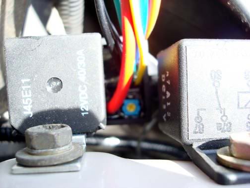
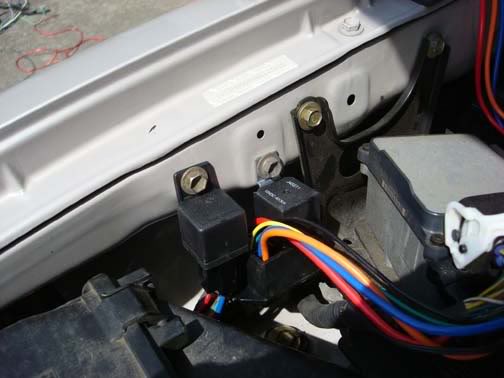
Using 10 mm bolts, attach the relays to the fender well.
I would recommend now that you remove the bolts that secure several components along the fender towards the firewall to aid in routing the wires necessary to power the fans and relays.
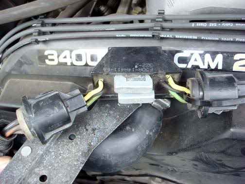
The Taurus fan I obtained was from a 1995 sedan with the 3.8 V6. While it may not be necessary, I obtained the entire cable for the fan. This included a rather unusual looking connection that the fan plugged into. I was never able to find out just what this connection does but I did discover that 1995 was the only year they installed this “control relay/fuse” connector. The Ford dealer could not explain its specific purpose but there had been issues with this fan set upin the previous years of Taurus. The determined this "control box" was critical to proper operation. The electrical diagrams for the car did not show them in the circuit, but the part was over $100, I figured, some engineer thought it was a good idea so I kept mine and installed it.
There are three (3) wires.
Blue – HI speed
Brown/Yellow – LO speed
Black – Ground for both fan speeds.
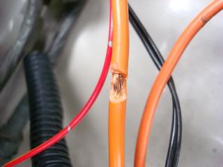
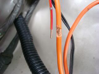
When I removed my fan from the donor vehicle, the Brown/yellow wires actually were two smaller wires spliced into a single larger gauge wire coming out of the connector. When I spliced the LO speed control wire from the control relay, I spliced in both the wires instead of cutting them near the factory splice at the larger gauge wire. This facilitated not having to either add wire to the relay wires or cut the other relay connections shorter. It just gave me more wire to work with.
The colors change coming out of the connectors to the box, then change back leaving the other side connector.
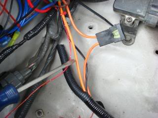
If you use this fan from a different year Taurus/Sable or Lincoln this connection may not be there. So to simplify the installation I just mounted the fan relay box to the radiator shroud.
It required drilling a hole in the shroud near the top. I had removed some of the shroud trailing edge material during my shroud modification so it made the placement very easy. If you do not remove this edge material you may need to modify where you place the fan box. My location followed the contour of the fan and direction of the mounting plate and wires. This also provided for easy attachment/splicing of the wires from the fan to the control relays.
Fan control
While it is not necessary to provide for dual control of this 2 speed fan, it is very practical. Any two or three position switch can provide you with the degree of control you desire. I chose to use a three position switch, ON-OFF-ON rocker switch. Having the two ON positions allow for control of the two speeds, one in thermostatic control, the other full manual control.
LO is wired in so that the thermostat controlled relay will operate the fan slow speed as required by engine temperature demands. HI is a full manual control which cuts the power to the slow speed of the fan while energizing the high speed setting independently. Selecting the OFF position removes power from both settings which can be useful in water crossings preventing water from splashing into the fan blades while they are moving which has been known to damage the plastic fan blades. Just another added bonus of this installation.
My choice of switch was an OEM rear heater fan speed selector switch from the center console of a 4runner. Choosing this switch allowed me the ease of installation into my driver’s dash and it is already marked as a fan! While I did have to modify the switch for proper operation, it is a very simple switch mod that requires minimal soldering skills. This fan switch can be acquired from almost any year 4runner and costs anywhere from free to less then $10.
If you chose this switch for your fan control, I would recommend that you also get not just the switch, but get both halves for a complete connector from the console that it plugs into. This provides the ability to remove the switch for either replacement or repair. Also you will be able to disconnect the switch if you need to remove the lower dash panel.
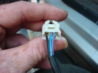
This is the switch as Toyota configured it for use in the rear heater speed select.
You will note the three (3) wires coming from the switch.
Blue/white – LO speed select (left side)
Black – common for both speeds (center)
Blue/red – HI speed (right side)
NOTE: I initially moved the blue/white from the common bus bar at the center/bottom of the switch to the upper left corner (see diagram) but found out the way the switch is internally set up this would not work correctly for our application. Eventually I had to move the black center contact to the lower bus bar. This would later be used as 12vdc input to the switch. While this made for easier identification of wiring, it involved a second wire removal and solder. If you don’t mind doing this, then you can do as I did. In hind sight, I would have left the wires configured and move only the black from center top to let top leaving the bus bar with the blue/white wire. You just have to remember the colors of the wires as you go to make this simpler.
Using a small pair of needle nose pliers, grasp the Blue/white wire near the contact. Move this up and down until the contact breaks free. Using some solder and flux, clean and solder the separated contact to the upper most left contact.
Check continuity using a multi-meter in both LO and HI switch positions and no continuity when the switch is in OFF.
Route the switch wire through the lower dash panel opening provided for a Toyota switch and connector.
Using a pull wire, push the pull wire through the drivers side wire boot on the engine side of the firewall into the passenger compartment.
Attach the wires from the switch to the end of the pull wire with tape. If you are planning to use LED indicators for fan operation, also route a control wire for the LO speed switch position along with the 3 other switch wires.
Pull the wires through the firewall into the engine compartment.
Now we are ready to begin wiring up the fan and switch control to the relays.
Note: I used TorqFlo brand Adjustable Electric Fan Thermostat p/n 733647 for the LO speed and Single Stage Electric Fan Thermostat p/n 733652 for the manual HI speed. My directions are for these two relay controllers. If you use a different brand, follow your installation instructions in conjunction with this setup.
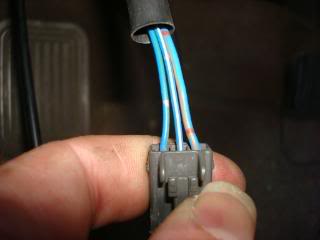
Once again identify the wires from the fan control switch. There are three wires. From the switch to the connector:
Black – 12vdc
Blue/White – LO speed
Blue/Red – HI speed
From the connector to the engine compartment:
Blue/Green – 12vdc
Blue/White – LO speed
Blue/Orange – HI speed
NOTE: When selecting, and then attaching the wires described, do NOT install any fuses at this time.
If the wire from the switch connector is not long enough to reach the Aux Fuse panel, route additional 16-18 gauge wire from the connector to reach the Aux fuse panel. Select an available contact location and crimp a female blade connector to the wire. Attach to the male blade connector on the fuse panel. Splice the other end to the 12 vdc wire from the switch. This is the source 12 vdc to operate the relays( LO or HI ).
Route two switch control wires to the right side of the vehicle to the relays. Identify which wire is for the LO speed relay and which one will be for the HI speed relay. Splice the two control wires (LO & HI) to their applicable wire from the switch connector in the engine bay.
Route a single 14 gauge wire from another available location on the accessory fuse panel to the relays until it is approximately 6 inches from the relays. I used red wire to correspond to the red wires on the relays. You will then add a second wire near the relays via a crimp. This is going to be the primary power inputs for the two fan speeds via the relay contacts. As this fan is only operating one speed at a time, this setup will save on wires and connections. Crimp a female blade connector and attach to an available connection on the Aux Fuse panel.
If you desire to install LED monitor indicators for fan operation, you will need to route a single 18 gauge wire from the switch location on the dash to the relays. I used a similar color coded wire from a salvaged wire harness (red/orange). This will connect to the output of the LO speed relay control power to the positive lead of the LED located next to the fan switch. When the fan runs, it will then light the indicator notifying you that the fan is in operation. This is only required for the LO speed only. The indicator for the HI speed is connected at the switch on the dash.
Install split loom around the wires that you routed from the fire wall and from the fuse panel to the relays. This provides for secure routing and protection for the wires. Tie wrap as necessary to secure the split loom in position.
Connecting the relays
Connect the Red 12 vdc wire from the Aux Fuse panel to the red leads of the two relays. This is your battery supplied power that operates the fan motor (30 amp)
Connect the LO switch wire to Yellow ignition source wire of the adjustable relay
Connect the HI switch wire to the Green wire of the Single stage relay. Normally the green wire would be for connection to the AC clutch. As the HI speed is our manually controlled fan speed, connecting to the green wire gives us direct switching control of the single stage relay.
These two wires (Yellow for the adjustable and Green for the single stage) provide relay operating power to close the relay contacts that then route our high current battery power to the operate the applicable fan speed.
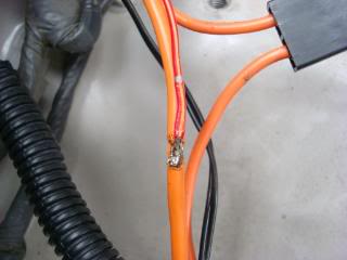
Connect the green output wire of the adjustable relay to the AC clutch wire. This wire is located on top of the AC compressor on the right side of the engine near the front. The wire from the AC clutch is located in a green split loom.
Remove the tape covering the two wires. The wire we will splice into is green/black
You can either use a splice connector or solder the wires. I stripped the insulation and soldered mine. Use electrical tape and seal the splice, insert back into split loom.
Combine the two black leads from the relays and crimp to a single loop end. Remove one of the relay mounting bolts, locate the loop end behind the relay and attach the bolt. This is the ground wire for the relays.
Route the orange power out wires from the relays along the right fender well across the radiator support to the fan speed wires. Locate the fan speed ground wire (black). Crimp a loop end connector large enough to accept the top radiator mounting bolt. Mount loop to bolt and tighten.
Route the temperature sensor wire and probe to the right side of the radiator. Choose a location near the upper hose water inlet. Use a small instrument like a pencil to open the fins slightly. Insert the probe into the radiator fins. Do not insert the probe into the fins so the probe extends past the radiator core. The probe should fit tightly. If the probe is not tight, use a small amount of JB QuikWeld to hold the probe in position. Only a very small amount is required to hold the probe properly. You do not want to clog the cooling fins.
Identify which wire is for the HI and LO speed of the fan. This can be accomplished by connecting the selected lead to the positive terminal of the battery with the ground connected and this will run the fan in the selected speed. Note which color wire is for which speed then connect the applicable wire to the either the LO or HI speed power wire coming from the relays as applicable.
If you routed the indicator wire for the LO speed, connect this indicator wire to the LO speed orange wire coming out of the adjustable relay.
NOTE: I had already installed the wires previously so I needed to strip insulation as I installed my indicator wire after the install had been completed.
If desired, you can splice using an appropriate size crimp or solder the indicator wire after stripping insulation.
Cut the indicator wire to length.
Solder the indicator wire to the fan power wire.
Use electrical tape and seal the splice.
Use split loom to enclose the wires from the fan to the relays. Use electrical tape as required to seal the ends of the split loom. Route the new cable along the inside of the radiator support, to the fender well going above the air box opening in the fender well. Use nylon tie wraps to secure the cable along the route. The Blue relay leads will not be used in this application so coil them up and secure to the fender well.
If you are not installing indicators for the fan speeds, verify your connections, ensure the switch is installed. Insert blade type fuses in the Aux fuse panel, 30 amp for the Fan supply, 5 amp in the switch connection position.
If you are installing Fan speed indicators I recommend the following ready made LED from Radio Shack.
After obtaining your indicators, continue as follows:
If the lower dash panel is installed remove the four 10 mm bolts securing the lower dash panel. The Fan Speed selector switch should be located in the lower row left most location.
Select the position for the LED indicators. Using 9/32” drill bit, drill out the mount positions.
Position the lower dash panel in its location, using a sharpie marker, mark the hole locations for the LED indicators in the mount/support for the dash.
Using a utility knife, cut out the area around the marked locations for the indicators. The housings for the LED indicators will fit into these cut outs. Be careful not to cut out too large of pieces. Remove the scrap plastic pieces.
Install the LED indicators in the lower dash panel. This is the view from the rear side.
Connecting up the HI side to the indicator uses a pick off point near the switch. Select a location about � way down the switch cable. Cut the sleeve exposing the 3 wires.
Locate the blue/red wire. Splice in a length of wire approximately 6” long. This will be the tap in for the HI speed indicator.
Install bullet connectors on each end of the black leads from the LEDs. Install the matching bullet connectors on two short pieces of wire approximately 3” long. Combine these two leads to a loop connector for attachment to a common ground point.
Using bullet connectors, connect the LO wire (blue/white) to the LED red lead wire designated for LO switch position. Connect the HI wire (blue/red) to the LED red lead wire designated for the HI switch position. Plug these connectors together These connectors will enable removal of the switch and lower panel along with the LEDs in the event of a failure or removal of the lower dash panel.
Reassemble the lower dash panel. Start the vehicle and test the switch positions. With the LO switch position selected, engine running at idle, operate the AC and verify the LO speed fan starts and you have a corresponding indication of operation.
Turn off the AC and then shift the selector switch to HI. Verify the high speed fan comes on and you have a corresponding indication.
NOTE: Due to the configuration when the HI position is selected, you should have both indicators operating. The LO speed coils will act as a generator sending a voltage back to the LO indicator resulting in both indicators illuminating. Also if the LO speed switch position is selected (normal operations) if air is entering the radiator at freeway speeds the fan will auto rotate illuminating the indicator, but it may be at about � illumination.
Adjustment of the Thermostat
After all tests have been completed, allow the vehicle to reach normal operating temperature. If the fan energizes before or at the correct operating temperature, some adjustment of the thermostat will be required. Toyota recommends operating temperature of around 185 degrees. The TorqFlo adjustable thermostat is factory set for 160 degrees. To adjust the thermostat, locate the adjustment potentiometer. This is a small blue box with a yellow adjustment screw in the center
NOTE: Adjustment range is only � of a turn. DO NOT force the screw past the stop point.
To increase the temperature the fan will turn on at rotate the set screw clockwise
To lower the temperature, turn the set screw counter-clockwise.
I drove my truck for about 10-15 minutes then adjusted the potentiometer so the fan would just come on. Then adjusted it backwards so it just shut off. This should set the fan turn on point at about 3-5 degrees above normal operating temperature. After I had everything installed and operating, I took my truck to the Toyota dealer and asked the mechanics there to do a thermo check for me. They read 146 degrees at the center of my radiator (no fan running). Then when I shifted the manual override to HI the temperature began to drop within about 10 seconds. After 30 seconds the temp had dropped 10 degrees.
At this setting I have only had a few times that my fan would come on after shutting down my truck. If this is an issue, or you encounter this as a common occurrence, you can readjust the settings for the turn on point. I would not recommend turning the switch to the OFF position as you may forget to turn it back on when driving again. If anyone has a suggestion for installation of an indicator that would come on at ignition, I am welcome to your suggestions. Please PM or email me directly.
Last edited by Ritzy4Runner; 07-09-2008 at 10:07 AM.


 07-26-2011, 08:41 AM
#5
Registered User

Join Date: Jul 2011
Location: Southern Oregon
Posts: 12
Likes: 0
Received 0 Likes
on
0 Posts
Okay, sorry to be the noob that brings this thread back from the dead. But I'm a little electrically retarded, so is there any chance of getting a wiring diagram of your fan set up? It is pretty much what I want to do with my 01 3.4 taco but I don't want to mess it up not knowing exactly what I am doing.
You'd make a poor boy very happy if you could do so, thanks
You'd make a poor boy very happy if you could do so, thanks
07-27-2011, 07:35 PM
#7
Registered User
Join Date: Nov 2006
Location: Tinley Park, IL
Posts: 710
Likes: 0
Received 0 Likes
on
0 Posts
Trending Topics
07-30-2011, 11:04 AM
#8

Absolutely nothing. Viscous coupling fans have been around for 100 years, and are still there on new 2012 models.
One improvement that new cars have is a smaller primary and a smaller secondary fan, that turns on in low driving speed situations.
Now that's a super reliable and redundant configuration that works well in all driving conditions.
One improvement that new cars have is a smaller primary and a smaller secondary fan, that turns on in low driving speed situations.
Now that's a super reliable and redundant configuration that works well in all driving conditions.
01-13-2012, 08:36 AM
#9
Registered User
Join Date: Nov 2007
Location: Gilbert, Az.
Posts: 680
Likes: 0
Received 0 Likes
on
0 Posts
Doing this modification to the radiator fan assembly is to increase the efficiency of the cooling system. Some people like the viscous clutch and others like an electric thermostatically controlled fan. Especially one that move's as much air as the Taurus fan does. Personally, I'm gathering the pieces to do this. My set up will vary from this write up though. However, this is a nice write up.
-Ted
-Ted
Last edited by snowshredder555; 01-13-2012 at 08:37 AM.
01-14-2012, 02:55 PM
#10
Registered User

Join Date: Dec 2011
Posts: 58
Likes: 0
Received 0 Likes
on
0 Posts
I agree with tunnelmotor99. This seems like a lot of effort for questionable gain. Any attempt to modify or reshape the shroud will compromise the integrity of it. The electric fan may have a higher CFM but that does not translate to improved cooling if the air is being pushed out the sides.


Thread
Thread Starter
Forum
Replies
Last Post
FS[SouthEast]: Mercury Villager Fan & DCC Fan Controller
coryc85
Misc Stuff (Vehicle Related)
6
09-09-2015 06:24 AM
icentropy
86-95 Trucks & 4Runners
10
07-11-2015 07:21 AM
tpd143
General Vehicle Related Topics (Non Year Related)
1
07-07-2015 09:06 AM


