Reverse Gauge Install on Gen 3
 07-17-2007, 08:20 PM
#1
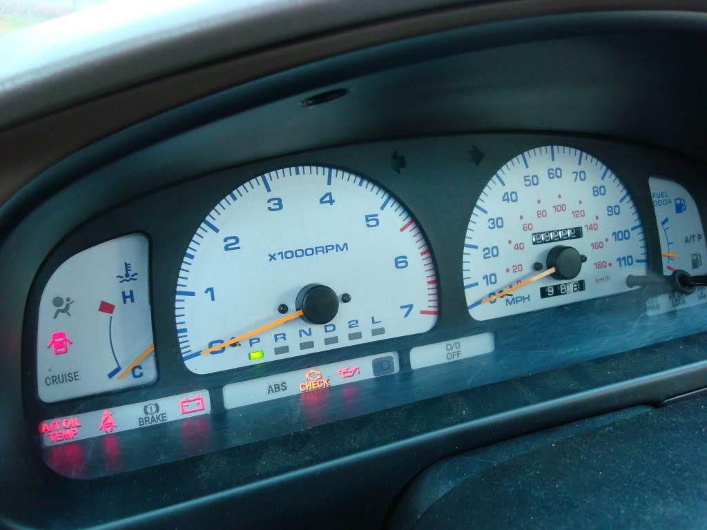
Just completed the install on my Silver Reverse gauges on my 1998 4Runner and do they look KEWL! 
Reverse gauge Install
This has to be one of the coolest mods you can do for your dash, talk about ?eye candy?! I happened upon this on eBay and was the first time I found one that had the same gauge faces as my 4runner. They are manufactured by Alfaotto. They do have a website www.alfaotto.com I noted that this website seems to be only for the wholesale market as I tried to get pricing and shipping details but it needed business information etc and I just said nah.
This gauge setup is really nice. They do make two versions one is white with Euro colors and the second which is the one I have is a silver colored face. Looks excellent in the cluster.
To install this gauge set first one needs to gather up some needed equipment.
# 1 Phillips screw driver (small)
#2 Phillips screw driver (medium)
Diagonal cutters
10mm socket
3/8 drive ratchet
6 inch extension
Crimper
#18 gauge wire crimps
Loop end crimps w/ 3/8 inch hole for grounding wire
18 gage wire
utility knife
magic marker
reinforced strap or packing tape
6 small nylon tie wraps
Most all reverse gauge sets come with holes for all the post, needles screws pretty much everything that you could encounter. You should not have to modify anything to your overlays, if you do then something is not right. Some have used double stick tape, superglue, adhesives etc. For my installation I required none of these additional items. Here is how I did it.
Remove the lower valance panel under the steering wheel by removing the 4 - 10mm screws holding it in place. Gently pull it free from the lower dash and lay it on the floorboard. This will expose the lower portion of the dash and main fuse panel.
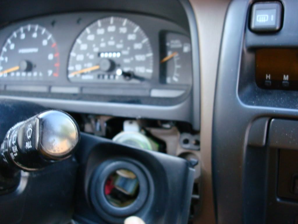
Pull the ignition key cover from around the ignition switch. Grasp the lower edge of the cover, pull it down and towards yourself. It will just snap out in your hand.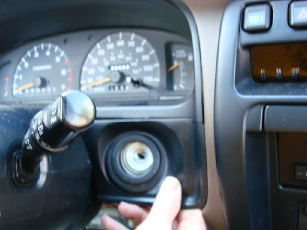
There are 4 screws that hold the dash face plate installed over the gauge cluster. Remove the right lower screw,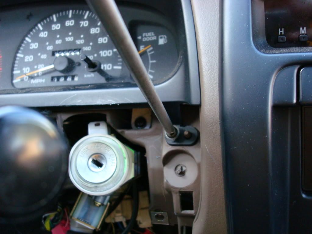
Left lower screw,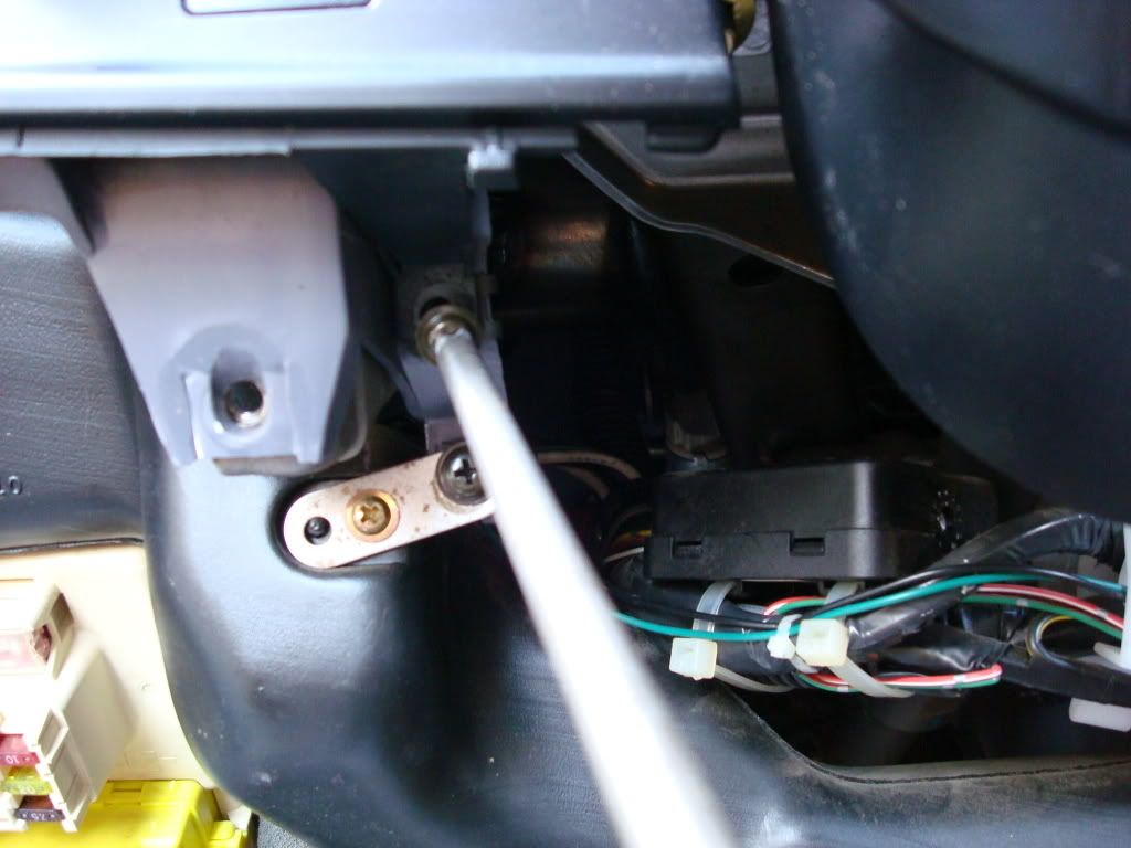
Left upper screw,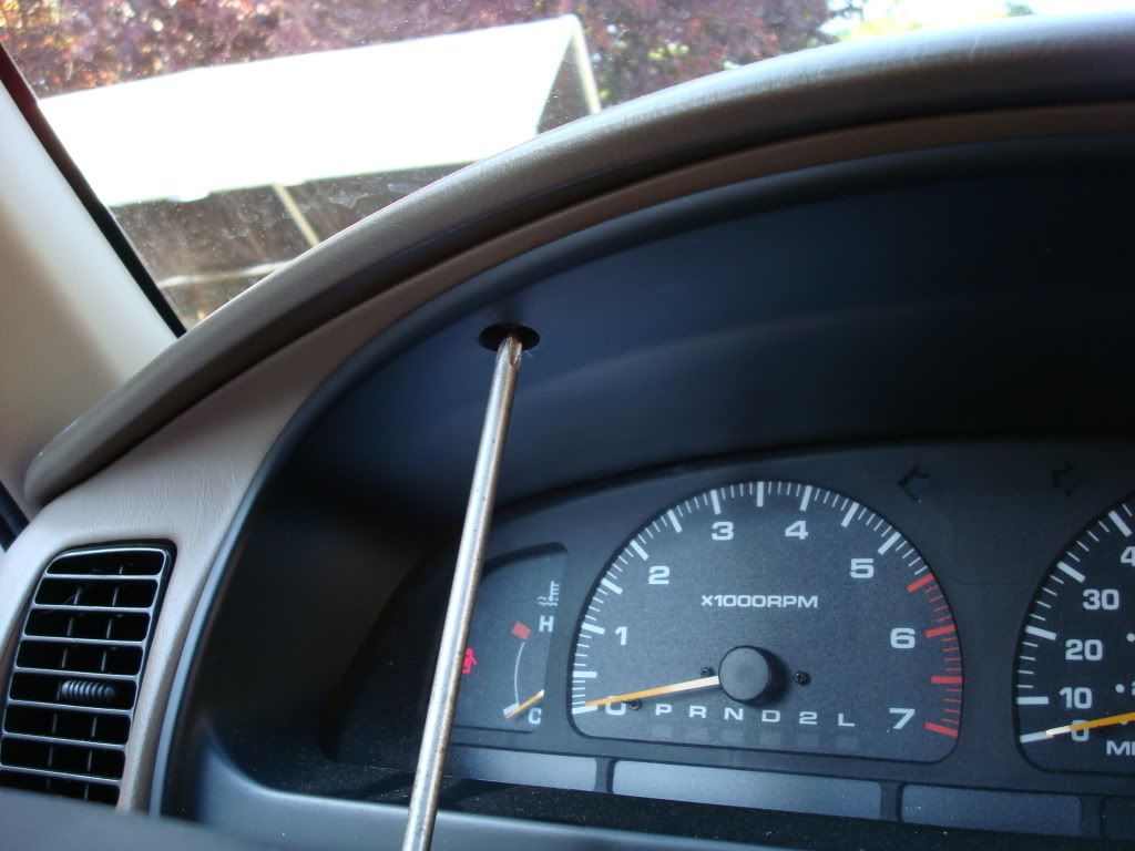
Right upper screw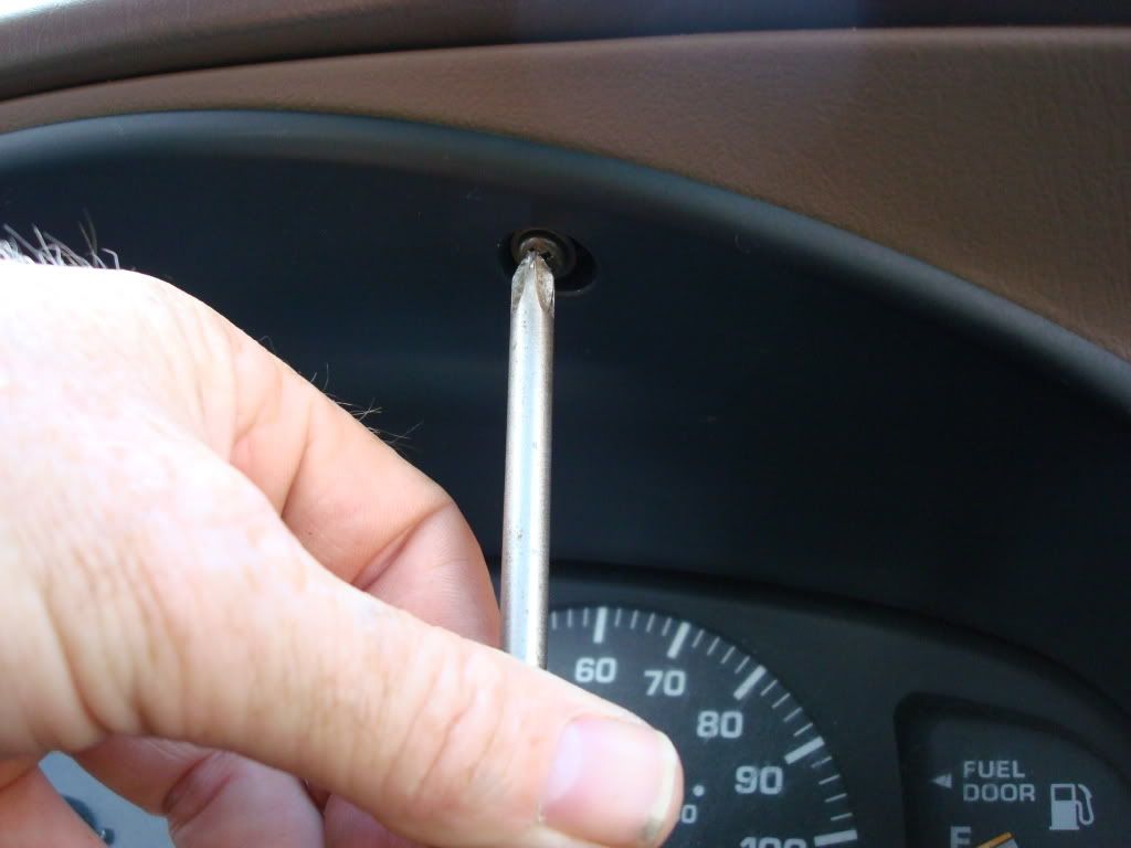
Grasping the lower left edge of the face plate, gently press the latch inward and lift the corner out from the dash. You will be able to see the Dimmer knob connector in the rear corner of the faceplate. Don?t pull this out too far as the Dimmer knob is still connected.
The top of the face plate will be loose and you will need to press dwon on the top center area just enough to allow you to pull it free of the crown of the dash.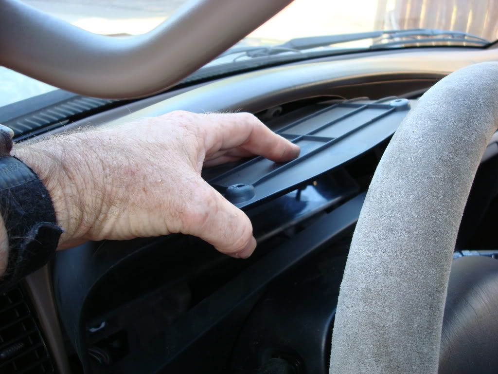
With the Dimmer knob connector now exposed, pull the faceplate out just enough to grasp the connector and squeeze the tab on the inside edge.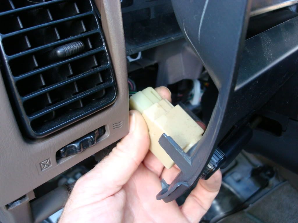
Wiggle the plug and when the tab releases you can pull the plug free of the socket. Remove the faceplate.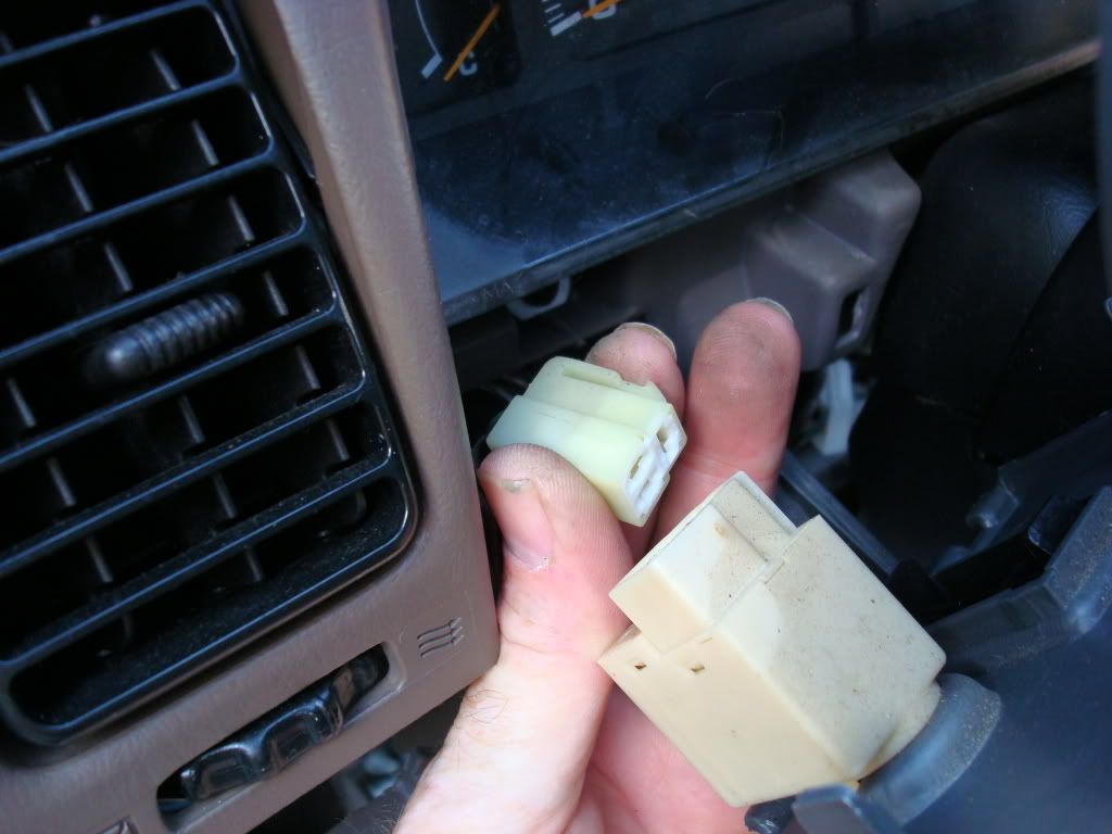
With the faceplate removed you expose the 4 screws that hold the gauge cluster in the dash.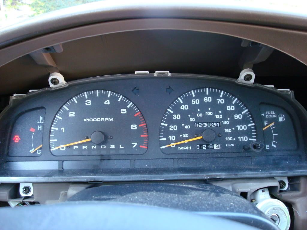
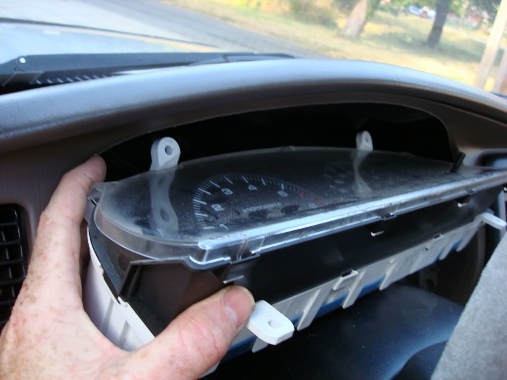
Once you have removed the 4 screws, tilt the gauge cluster from the bottom, upward at the same time pulling gently towards the steering wheel. Continue to rotate the cluster upward until the cluster is free of the dash edges. You should be able to see all 4 connectors in the back of the cluster. Do not try to pull the cluster out too far during this step.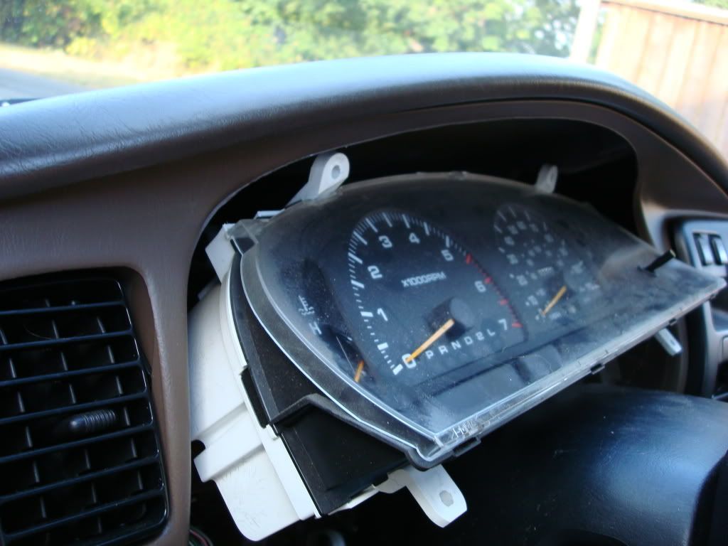
Return the cluster to an upright position but slightly pulled away from the dash so as to expose the left side connector. While holding the cluster with your right hand, squeeze the tab on the top of the first connector with your left and gently pull the plug from the cluster.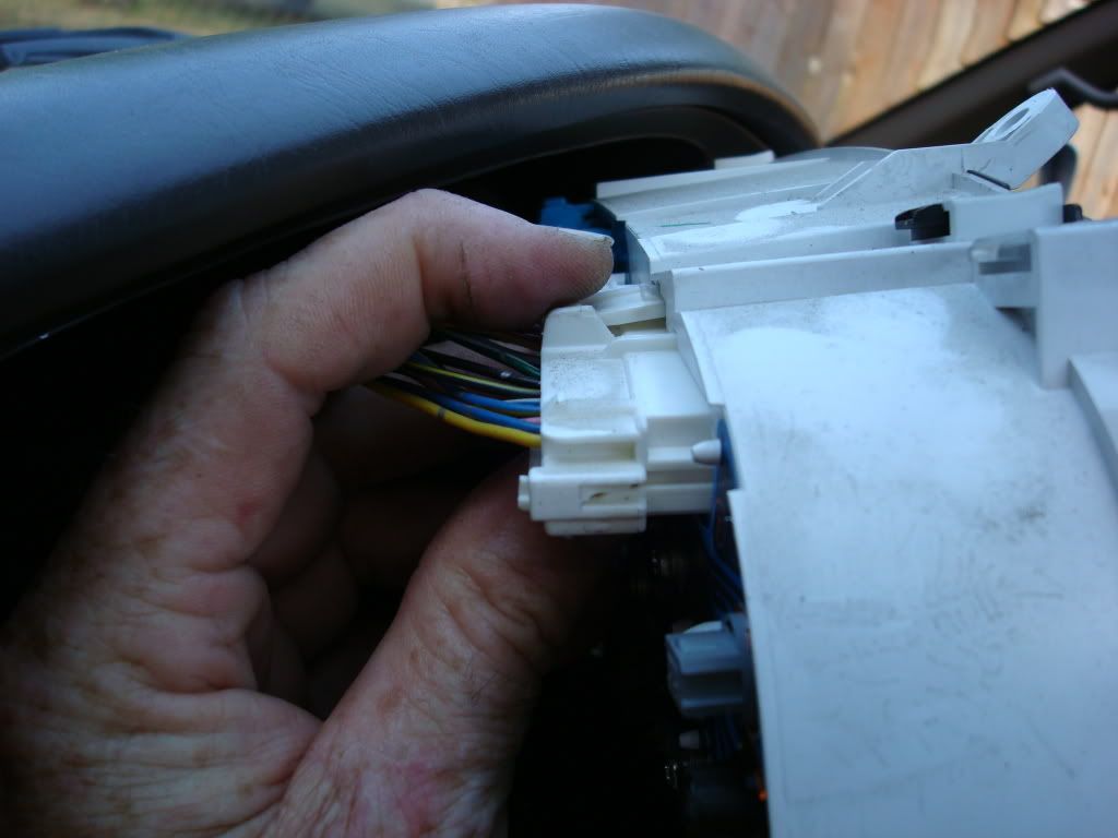
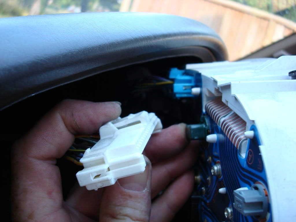
Begin moving towards the right side of the cluster and perform the same action on the next three plugs.
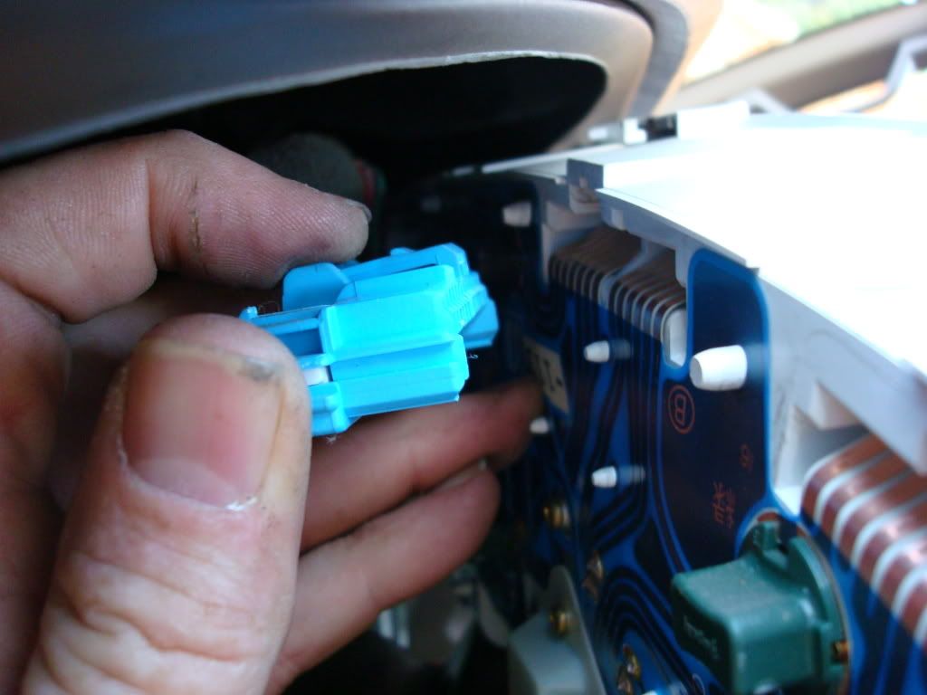
Once all 4 plugs are removed lift the gauge cluster from the dash and set aside.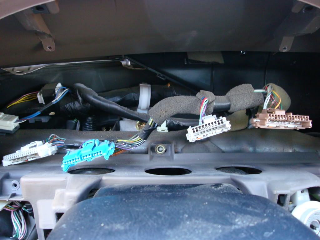
Removal of the gauge front cover.
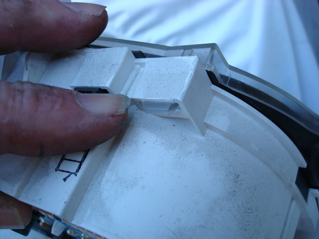
The clear protective cover is attached by 8 plastic clips inserted into receiver loops in the gauge cluster housing. Using your fingers gently press downward on the tabs and push the tabs through the loop. I started with the top clips and then flipped the cluster over to access the lower clips.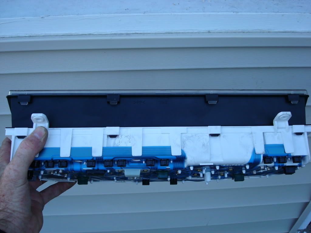


Once these clips are released the cover will lift off very easily.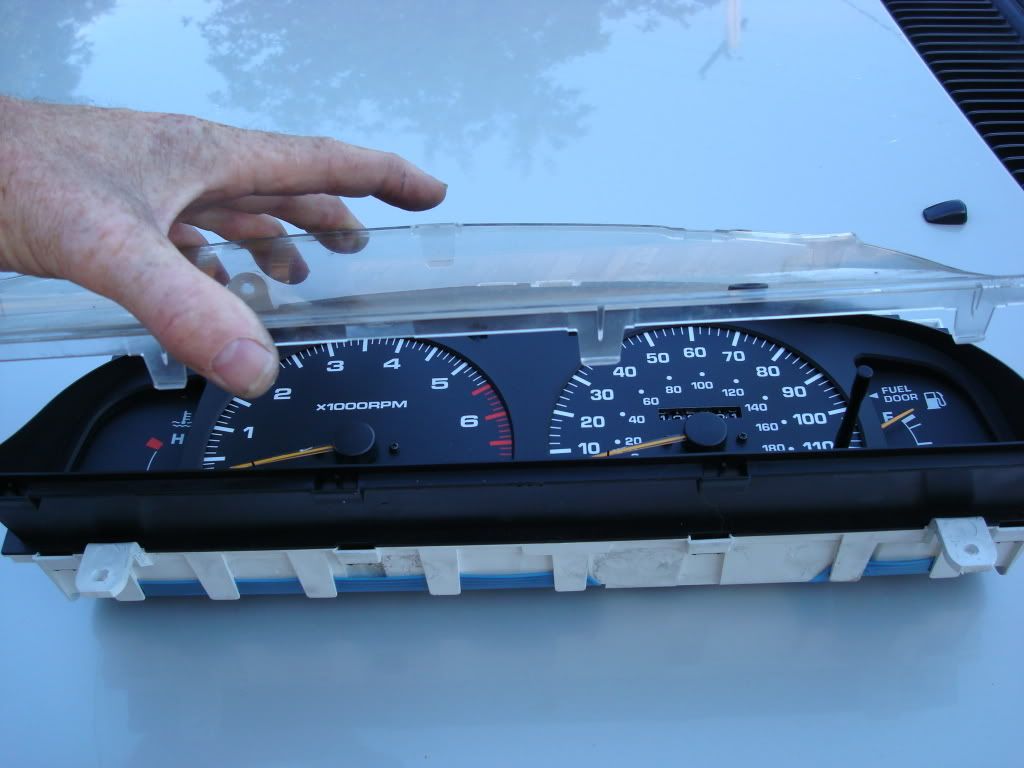
The black bezel for the gauge cluster is now exposed and is removed in the same manner as the clear cover.
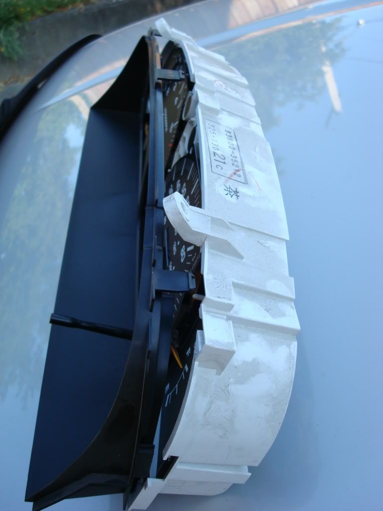
Once all of the bezel clips are removed then set the bezel aside.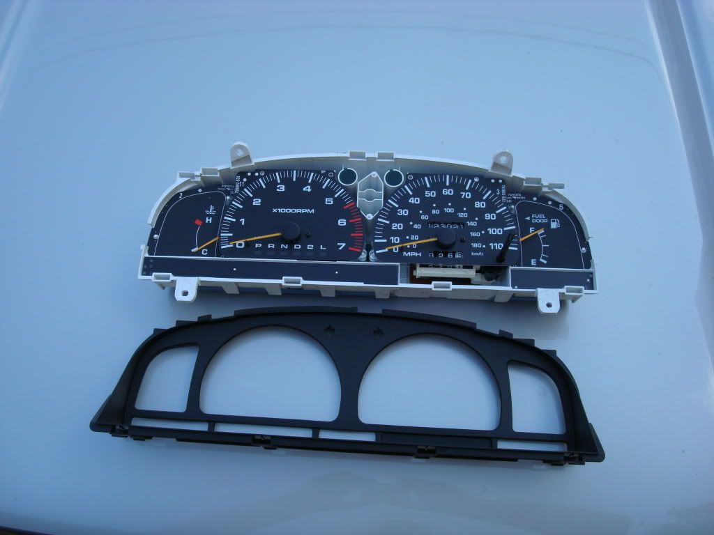
There are a couple of different approaches on these next few steps. After my install I would recommend the following: Install both side gauge overlays first then the center gauges, Tachometer, then Speedometer. This just facilitates mounting and minimizing gauge overlay flexing during installation.
I should explain the following operation. You will need to remove the gauge mounting screws from the faces of the OEM gauges. These are small black screws with lock washers. Be sure to use a small enough Phillips tip screw driver. Do so carefully and as you start to back out the screws, press down on the area under and next to each screw. They will stick to the lock washers so they need to be released from the washer or you will lift the gauge faces and possibly bend the needles of the gauges. When you remove screws, I would only do this one gauge at a time. Most other installations I have seen here do not have you remove these screws and have you drill out, cut or otherwise enlarge the holes. I found out that if you use the mount screws you eliminate the need for adhesive or tape to hold the overlays in place. The purpose of the gauge face screws is to hold the gauge face plates in position. This will be accomplished with our new overlays installed on top of the OEM gauge faces.
Each gauge has two screws. For the Temp and gas gauge, you only need remove the lower screw. The overlays included in my kit only required the lower screw mounting. To remove these screws you will need to lift the lower edge of the tach and speedo gauges to allow the screwdriver to access the head of the screw. After removing the lower screw, place the overlay on the gauge to see where the attaching wires for the overlay go across the cluster housing. You will need to mark this spot with your magic marker. An area the same width as the wire is all that is needed. This will provide for a channel for the wire to rest in without being pinched when we re-install the bezel.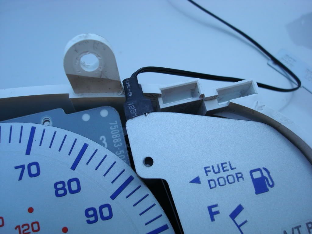
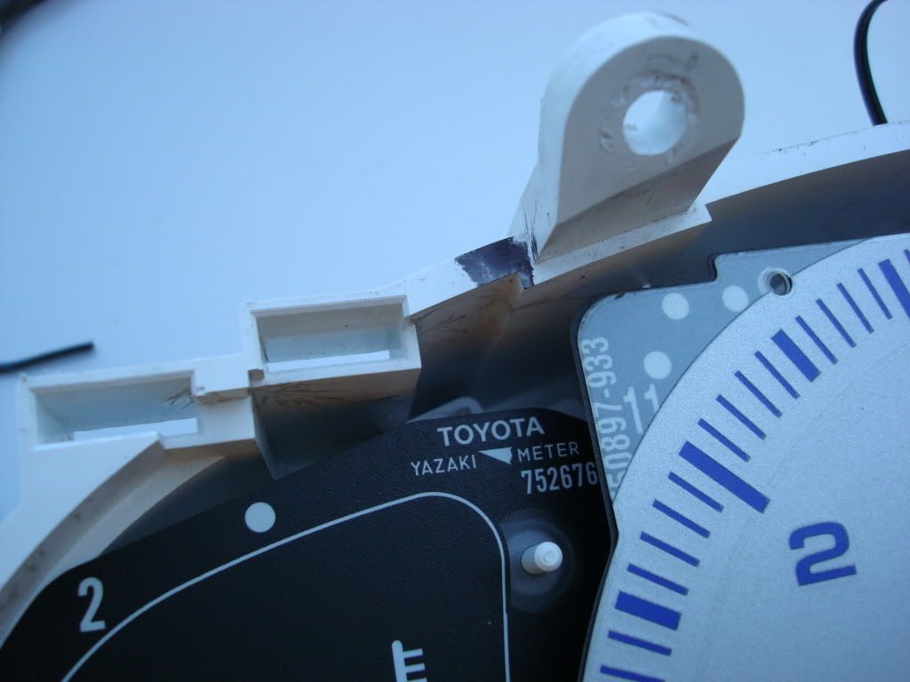
After marking the location of the overlay wires, using the utility knife you will need to cut away the plastic only enough to allow the wire to be able to lay in this channel without being pinched. I found that if you cut the edge just deep enough to remove the wide ridge then you will have perfect clearance (approx 1/8 inch).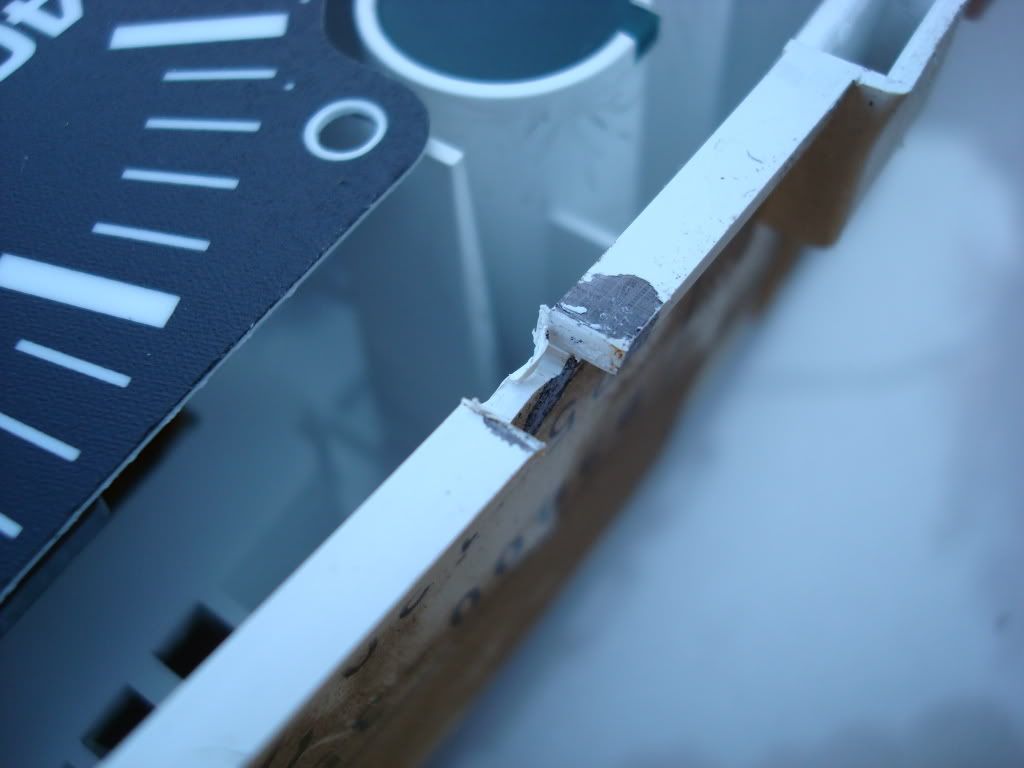
Due to the location of the wires for the overlays, there was not much clearance for the wire attachment points on the overlays to be inside of the cluster housing without cutting a notch.. In addition, I had to bend the wires slightly to get them to fit properly but be careful when doing so as you can damage the attachment points to the overlays. I was able to press them down slightly and once the bezel is installed they will be maintained in a flush position.
Once the wire notches are cut, slip the overlay under the gauge needle. Align the mounting hole with the gauge hole and install the set screw. Tighten down but do not over-torque the screw. These are only mounted in plastic.
The real test will no be installing the overlays on the Tach and Speedo. I did the tachometer first. Remove the two set screws. Gently holding the needle slip the needle through the center overlay hole . When you set it down it will need to be placed over the needle stop post. The needle stop post has a rubber grommet surrounding the post itself. Once the gauge overlay is on the gauge face you will need to press the overlay over this grommet. I just used my finger nails and pressed it down along the edges of the overlay hole. It literally popped into the overlay post hole and provided a great tight secure hold.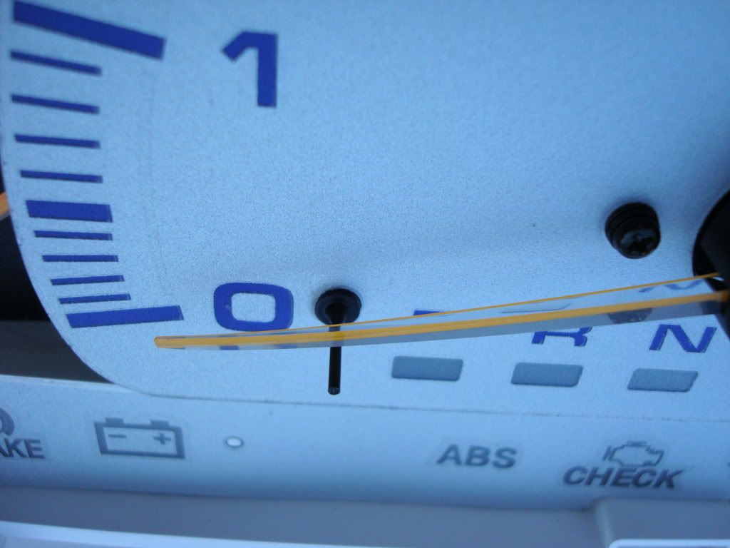
Next you will need to reinstall the two set screws. Remember that the gauge faces as well as the overlay need to be properly aligned or they will impede the movement of the gauges. Once the gauges are properly centered, tighten down the set screws but not completely. Gently move the gauge needle in its proper direction of travel (Speedometer and Tachometer only) to ensure freedom of movement. When you are satisfied that the gauges are free moving, tighten down the set screws.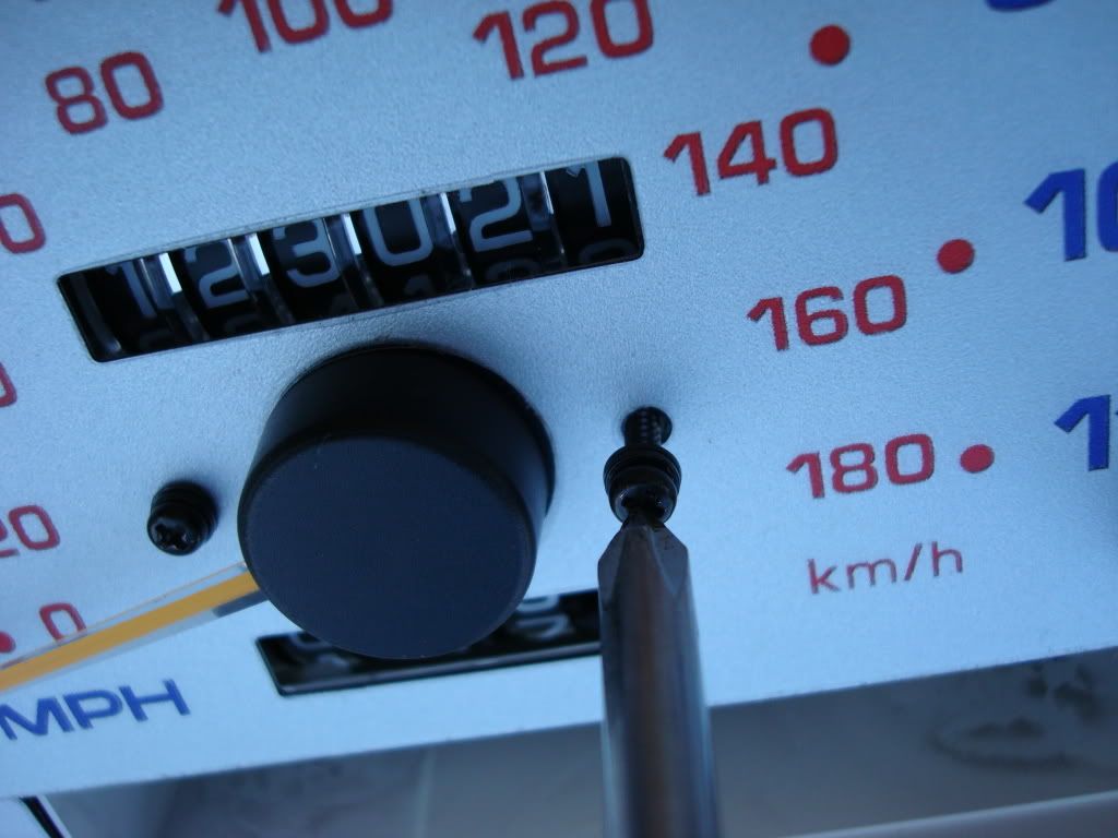
The Speedometer will present a bit of a challenge. You are going to have to deal with the trip odometer post as well as the gauge needle and needle stop post. Place the overlay over the trip odometer first. Gently move the MPH needle until you can slip needle through the center hole. This requires lifting the end of the needle upwards. Be very careful doing this as you can easily damage the needle. One the need is through the center hole, rotate the gauge face into position. Be mindful that you will also need to lift the edge over the needle stop post. Once again using finger nails, press the edges of the stop post grommet until it fits through and holds the gauge overlay. Check for smooth operation of the speedo needle and when satisfied, replace the set screws.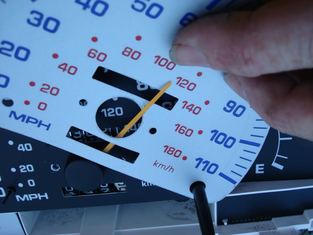
My gauge set also included the non-lighted overlays for the warning lights in the lower portion of the gauge cluster. I used a small bit of spray adhesive dabbed on the edges so as not to block the light from the indicators. This may not be necessary as the bezel snaps down over the warning light displays and has small mounting alignment holes as does the OEM covers.
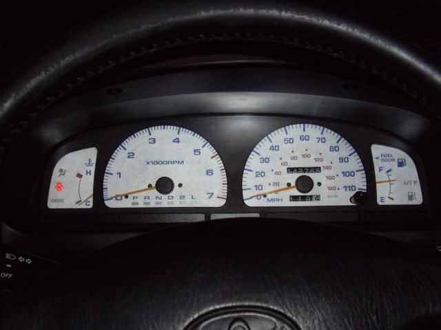
With all the overlays installed in the gauge cluster housing, you should have something that looks like this.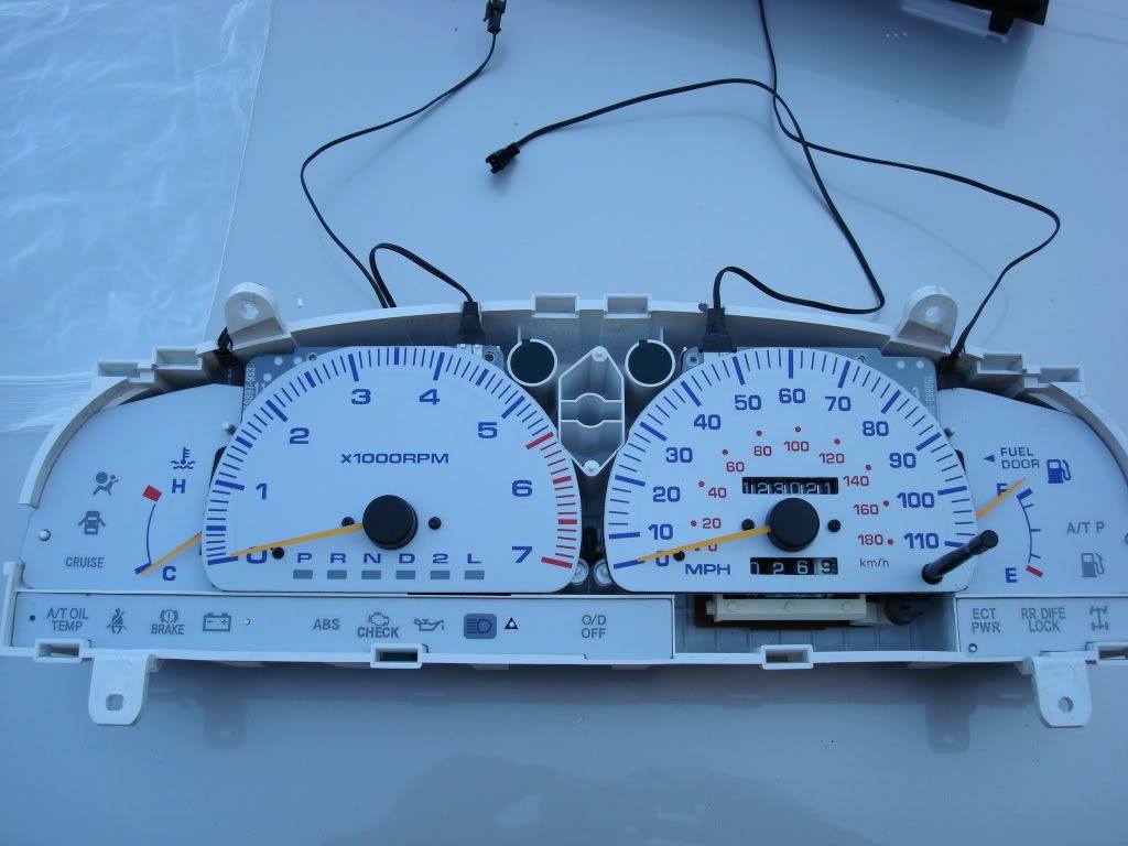
It has been recommended to seal the notches where the overlay wires come through the back of the gauge housing to seal it from dust and debris. This would be the opportune time to do this if desired.
Ensure the overlay wires are properly routed through their respective notches and all kinks and bends removed. Use a small amount of clear silicone sealant to each of the notches made for the overlay wires. Now the bezel will be re-installed. Install the bezel while the silicone is still wet. Remember that you now have some adhesive holding the bezel in place besides the clips. Place the bezel over the housing ensuring that all tabs are aligned with their loops on the housing and press it into place. Check each tab to ensure proper locking of the tabs.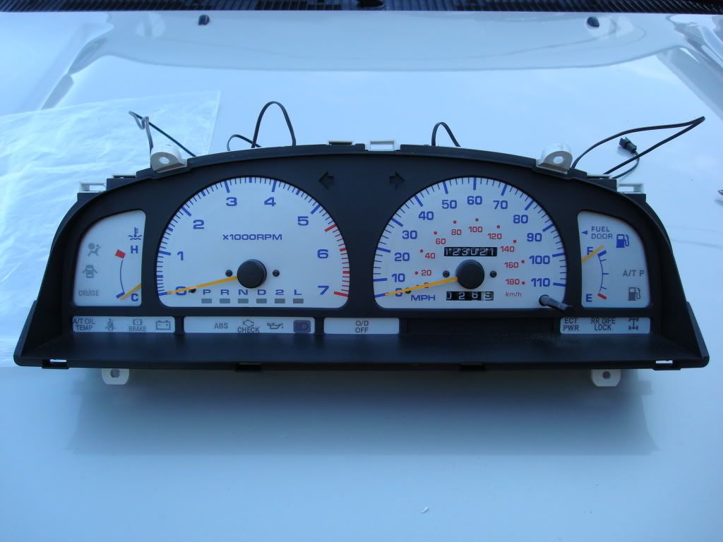
The clear gauge cover also re-installs in the same manner. Ensure that all tabs are properly latched.
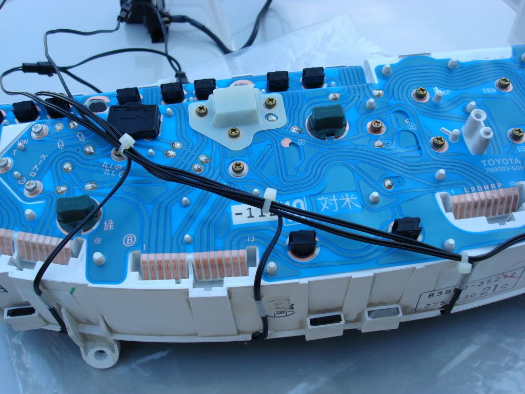
The gauge overlay wiring will now be attached to the top of the housing. I used reinforced packaging tape. Cutting 4 strips approximately1/2 inch wide and 1 inch long, I placed these over the wires at the point just below where they exit the top of the housing.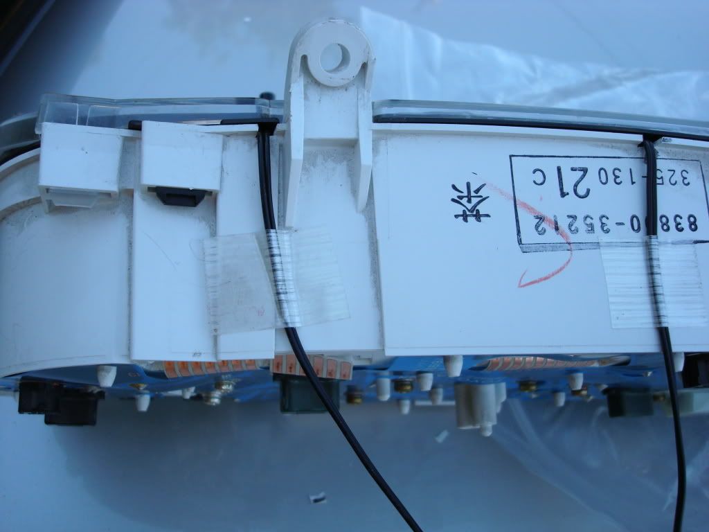
This places all 4 wires along the top of the housing and simplifies the routing of the wires along the back of the housing also preventing them from interfering with any connections when installed back in the dash.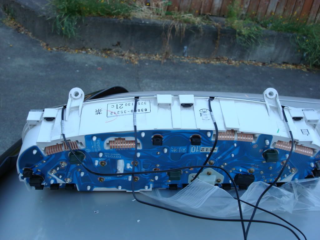
Starting with the right side of the housing, I aligned the wire from the first overlay along the top edge of the housing until reaching the second wire. I placed a slight 90 degree angle in the second wire and attached a nylon tie wrap to hold the position of the first two wires. I then proceeded along the back adding each successive wire and another tie wrap at each juncture. Finally trimming each tie wrap for a finished professional look.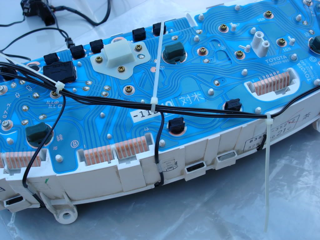
The inverter and controller is now attached to the 4 wire leads and our gauge cluster is ready for placing back in the dash. Locate the best route for the inverter and the power supply wire for the inverter. The supply wire consists of two small wires inthis case one red, one black. You need to ensure these two wires are routed to the main fuse panel with some excess length to work with. Place the cluster back into the dash right end first. Leave enough room to get your hand behind all the way to the right side connector. Grasp the connector and press it into position until you hear/feel it snap into place. Continue with each succeeding plug until all 4 are securely installed.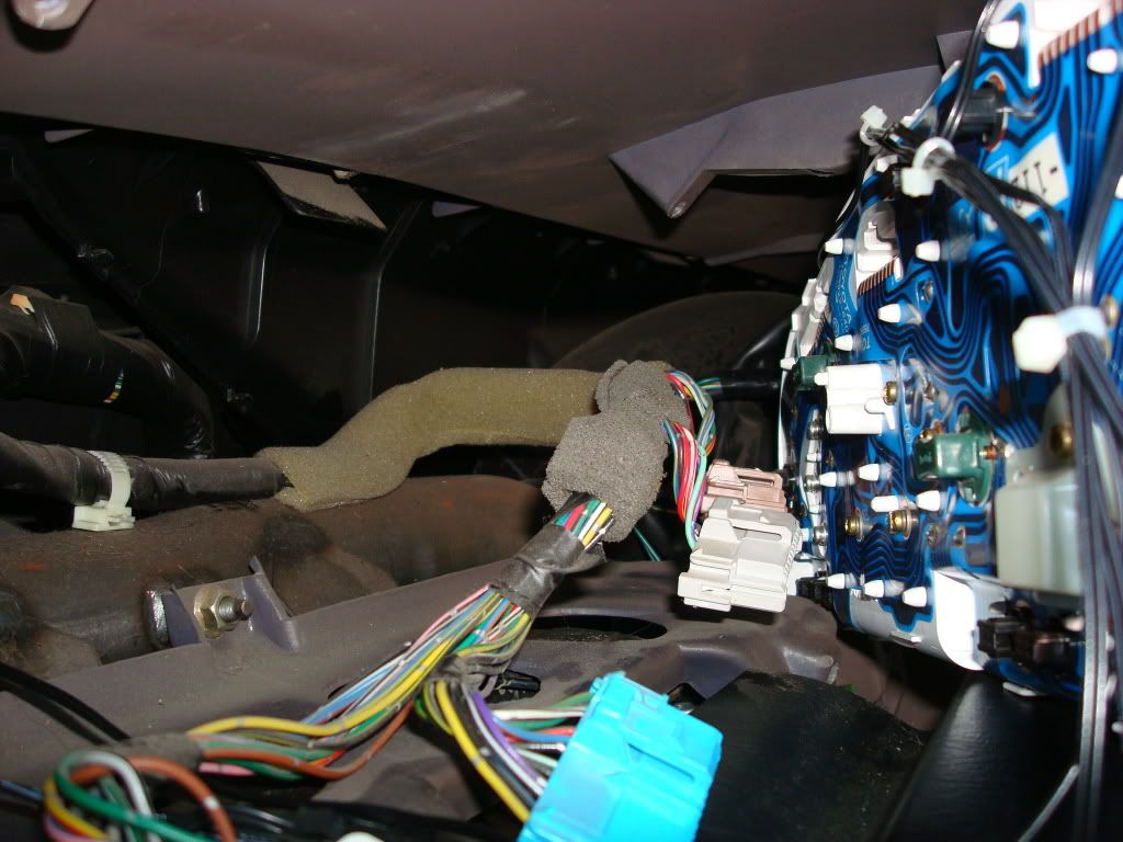
Once the gauge cluster is installed secure it with the 4 screws removed earlier. Reinstall the dash faceplate with the 4 screws. And we have gauges.
Next we need to hook up power for our gauges. The wire we will connect our red power wire to is the line for the parking lights. This will be a solid green wire that has small silver blocks on it. This wire is the 4th wire from the left.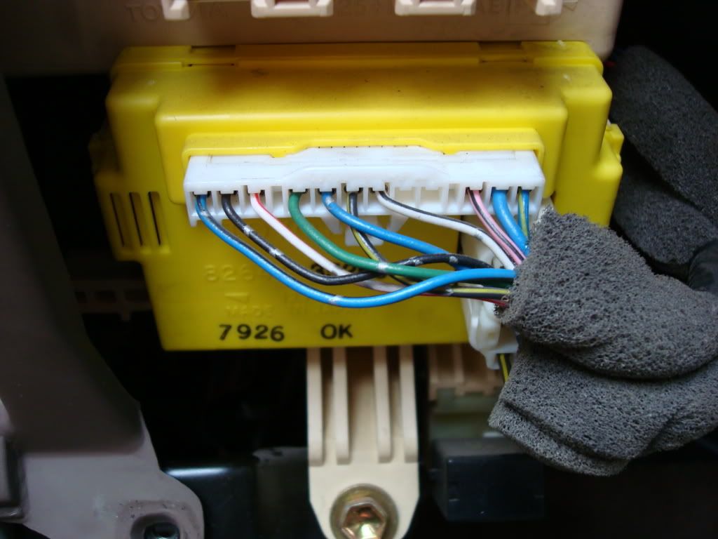
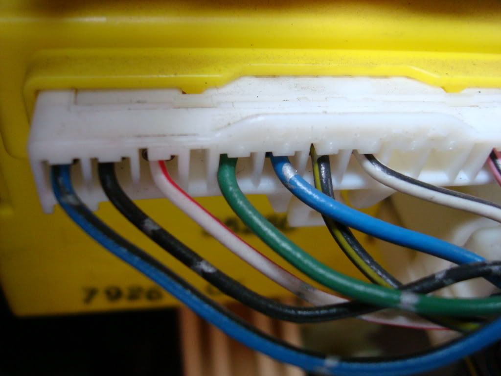
Remove the main fuse panel connector. Squeeze the tab at the top and pull the connector out. The wire bundle is covered with a foam covering that may need to be removed an inch or two depending on where you decide to cut the wire. Cut and strip the end of the green wire in preparation for splicing.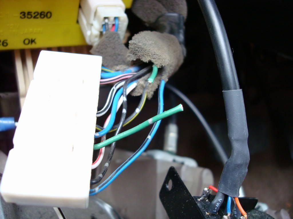
Install a crimp on the connector side of the plug ensuring that both the green wire and the red wire from our gauge Inverter is properly inserted into the crimp. Once complete, insert the other end of the green wire and crimp. As for the black or ground wire from the inverter, I chose to use a short piece of wire and a loop end crimp for placement in the bracket just below the main fuse panel.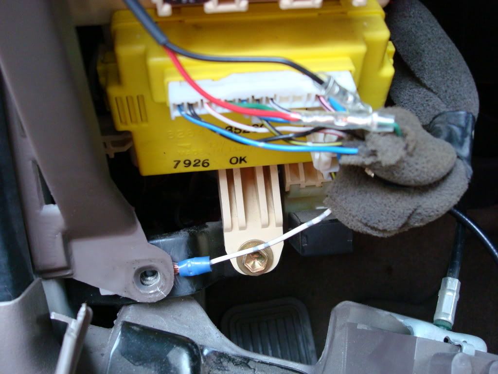
The loop crimp ground wire is then slipped between the plastic cover and the chassis mount for the lower panel. This mount is just to the left and below the main fuse panel. Line up the holes and the plastic panel holds the crimp in place until the lower valance is installed and tightened. Reinstall the lower valance with the 4 ? 10mm screws. Select either blue or green on the selector control for the inverter. Check the Ignition switch and see if we light up the proper indications.
Next, turn on parking lights and we have a successful install.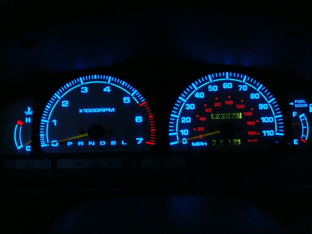
I did not have a place to mount the control switch plate for the inverter at this time, so I selected the light color I liked, then set the intensity for about mid position. I then located this inside the lower valance behind the main fuse panel cover. If I need to change a setting, I can easily retrieve the switch until a more permanent solution is available. Hope you enjoyed.
Reverse gauge Install
This has to be one of the coolest mods you can do for your dash, talk about ?eye candy?! I happened upon this on eBay and was the first time I found one that had the same gauge faces as my 4runner. They are manufactured by Alfaotto. They do have a website www.alfaotto.com I noted that this website seems to be only for the wholesale market as I tried to get pricing and shipping details but it needed business information etc and I just said nah.
This gauge setup is really nice. They do make two versions one is white with Euro colors and the second which is the one I have is a silver colored face. Looks excellent in the cluster.
To install this gauge set first one needs to gather up some needed equipment.
# 1 Phillips screw driver (small)
#2 Phillips screw driver (medium)
Diagonal cutters
10mm socket
3/8 drive ratchet
6 inch extension
Crimper
#18 gauge wire crimps
Loop end crimps w/ 3/8 inch hole for grounding wire
18 gage wire
utility knife
magic marker
reinforced strap or packing tape
6 small nylon tie wraps
Most all reverse gauge sets come with holes for all the post, needles screws pretty much everything that you could encounter. You should not have to modify anything to your overlays, if you do then something is not right. Some have used double stick tape, superglue, adhesives etc. For my installation I required none of these additional items. Here is how I did it.
Remove the lower valance panel under the steering wheel by removing the 4 - 10mm screws holding it in place. Gently pull it free from the lower dash and lay it on the floorboard. This will expose the lower portion of the dash and main fuse panel.
Pull the ignition key cover from around the ignition switch. Grasp the lower edge of the cover, pull it down and towards yourself. It will just snap out in your hand.
There are 4 screws that hold the dash face plate installed over the gauge cluster. Remove the right lower screw,
Left lower screw,
Left upper screw,
Right upper screw
Grasping the lower left edge of the face plate, gently press the latch inward and lift the corner out from the dash. You will be able to see the Dimmer knob connector in the rear corner of the faceplate. Don?t pull this out too far as the Dimmer knob is still connected.
The top of the face plate will be loose and you will need to press dwon on the top center area just enough to allow you to pull it free of the crown of the dash.
With the Dimmer knob connector now exposed, pull the faceplate out just enough to grasp the connector and squeeze the tab on the inside edge.
Wiggle the plug and when the tab releases you can pull the plug free of the socket. Remove the faceplate.
With the faceplate removed you expose the 4 screws that hold the gauge cluster in the dash.
Once you have removed the 4 screws, tilt the gauge cluster from the bottom, upward at the same time pulling gently towards the steering wheel. Continue to rotate the cluster upward until the cluster is free of the dash edges. You should be able to see all 4 connectors in the back of the cluster. Do not try to pull the cluster out too far during this step.
Return the cluster to an upright position but slightly pulled away from the dash so as to expose the left side connector. While holding the cluster with your right hand, squeeze the tab on the top of the first connector with your left and gently pull the plug from the cluster.
Begin moving towards the right side of the cluster and perform the same action on the next three plugs.
Once all 4 plugs are removed lift the gauge cluster from the dash and set aside.
Removal of the gauge front cover.
The clear protective cover is attached by 8 plastic clips inserted into receiver loops in the gauge cluster housing. Using your fingers gently press downward on the tabs and push the tabs through the loop. I started with the top clips and then flipped the cluster over to access the lower clips.
Once these clips are released the cover will lift off very easily.
The black bezel for the gauge cluster is now exposed and is removed in the same manner as the clear cover.
Once all of the bezel clips are removed then set the bezel aside.
There are a couple of different approaches on these next few steps. After my install I would recommend the following: Install both side gauge overlays first then the center gauges, Tachometer, then Speedometer. This just facilitates mounting and minimizing gauge overlay flexing during installation.
I should explain the following operation. You will need to remove the gauge mounting screws from the faces of the OEM gauges. These are small black screws with lock washers. Be sure to use a small enough Phillips tip screw driver. Do so carefully and as you start to back out the screws, press down on the area under and next to each screw. They will stick to the lock washers so they need to be released from the washer or you will lift the gauge faces and possibly bend the needles of the gauges. When you remove screws, I would only do this one gauge at a time. Most other installations I have seen here do not have you remove these screws and have you drill out, cut or otherwise enlarge the holes. I found out that if you use the mount screws you eliminate the need for adhesive or tape to hold the overlays in place. The purpose of the gauge face screws is to hold the gauge face plates in position. This will be accomplished with our new overlays installed on top of the OEM gauge faces.
Each gauge has two screws. For the Temp and gas gauge, you only need remove the lower screw. The overlays included in my kit only required the lower screw mounting. To remove these screws you will need to lift the lower edge of the tach and speedo gauges to allow the screwdriver to access the head of the screw. After removing the lower screw, place the overlay on the gauge to see where the attaching wires for the overlay go across the cluster housing. You will need to mark this spot with your magic marker. An area the same width as the wire is all that is needed. This will provide for a channel for the wire to rest in without being pinched when we re-install the bezel.
After marking the location of the overlay wires, using the utility knife you will need to cut away the plastic only enough to allow the wire to be able to lay in this channel without being pinched. I found that if you cut the edge just deep enough to remove the wide ridge then you will have perfect clearance (approx 1/8 inch).
Due to the location of the wires for the overlays, there was not much clearance for the wire attachment points on the overlays to be inside of the cluster housing without cutting a notch.. In addition, I had to bend the wires slightly to get them to fit properly but be careful when doing so as you can damage the attachment points to the overlays. I was able to press them down slightly and once the bezel is installed they will be maintained in a flush position.
Once the wire notches are cut, slip the overlay under the gauge needle. Align the mounting hole with the gauge hole and install the set screw. Tighten down but do not over-torque the screw. These are only mounted in plastic.
The real test will no be installing the overlays on the Tach and Speedo. I did the tachometer first. Remove the two set screws. Gently holding the needle slip the needle through the center overlay hole . When you set it down it will need to be placed over the needle stop post. The needle stop post has a rubber grommet surrounding the post itself. Once the gauge overlay is on the gauge face you will need to press the overlay over this grommet. I just used my finger nails and pressed it down along the edges of the overlay hole. It literally popped into the overlay post hole and provided a great tight secure hold.
Next you will need to reinstall the two set screws. Remember that the gauge faces as well as the overlay need to be properly aligned or they will impede the movement of the gauges. Once the gauges are properly centered, tighten down the set screws but not completely. Gently move the gauge needle in its proper direction of travel (Speedometer and Tachometer only) to ensure freedom of movement. When you are satisfied that the gauges are free moving, tighten down the set screws.
The Speedometer will present a bit of a challenge. You are going to have to deal with the trip odometer post as well as the gauge needle and needle stop post. Place the overlay over the trip odometer first. Gently move the MPH needle until you can slip needle through the center hole. This requires lifting the end of the needle upwards. Be very careful doing this as you can easily damage the needle. One the need is through the center hole, rotate the gauge face into position. Be mindful that you will also need to lift the edge over the needle stop post. Once again using finger nails, press the edges of the stop post grommet until it fits through and holds the gauge overlay. Check for smooth operation of the speedo needle and when satisfied, replace the set screws.
My gauge set also included the non-lighted overlays for the warning lights in the lower portion of the gauge cluster. I used a small bit of spray adhesive dabbed on the edges so as not to block the light from the indicators. This may not be necessary as the bezel snaps down over the warning light displays and has small mounting alignment holes as does the OEM covers.
With all the overlays installed in the gauge cluster housing, you should have something that looks like this.
It has been recommended to seal the notches where the overlay wires come through the back of the gauge housing to seal it from dust and debris. This would be the opportune time to do this if desired.
Ensure the overlay wires are properly routed through their respective notches and all kinks and bends removed. Use a small amount of clear silicone sealant to each of the notches made for the overlay wires. Now the bezel will be re-installed. Install the bezel while the silicone is still wet. Remember that you now have some adhesive holding the bezel in place besides the clips. Place the bezel over the housing ensuring that all tabs are aligned with their loops on the housing and press it into place. Check each tab to ensure proper locking of the tabs.
The clear gauge cover also re-installs in the same manner. Ensure that all tabs are properly latched.
The gauge overlay wiring will now be attached to the top of the housing. I used reinforced packaging tape. Cutting 4 strips approximately1/2 inch wide and 1 inch long, I placed these over the wires at the point just below where they exit the top of the housing.
This places all 4 wires along the top of the housing and simplifies the routing of the wires along the back of the housing also preventing them from interfering with any connections when installed back in the dash.
Starting with the right side of the housing, I aligned the wire from the first overlay along the top edge of the housing until reaching the second wire. I placed a slight 90 degree angle in the second wire and attached a nylon tie wrap to hold the position of the first two wires. I then proceeded along the back adding each successive wire and another tie wrap at each juncture. Finally trimming each tie wrap for a finished professional look.
The inverter and controller is now attached to the 4 wire leads and our gauge cluster is ready for placing back in the dash. Locate the best route for the inverter and the power supply wire for the inverter. The supply wire consists of two small wires inthis case one red, one black. You need to ensure these two wires are routed to the main fuse panel with some excess length to work with. Place the cluster back into the dash right end first. Leave enough room to get your hand behind all the way to the right side connector. Grasp the connector and press it into position until you hear/feel it snap into place. Continue with each succeeding plug until all 4 are securely installed.
Once the gauge cluster is installed secure it with the 4 screws removed earlier. Reinstall the dash faceplate with the 4 screws. And we have gauges.
Next we need to hook up power for our gauges. The wire we will connect our red power wire to is the line for the parking lights. This will be a solid green wire that has small silver blocks on it. This wire is the 4th wire from the left.
Remove the main fuse panel connector. Squeeze the tab at the top and pull the connector out. The wire bundle is covered with a foam covering that may need to be removed an inch or two depending on where you decide to cut the wire. Cut and strip the end of the green wire in preparation for splicing.
Install a crimp on the connector side of the plug ensuring that both the green wire and the red wire from our gauge Inverter is properly inserted into the crimp. Once complete, insert the other end of the green wire and crimp. As for the black or ground wire from the inverter, I chose to use a short piece of wire and a loop end crimp for placement in the bracket just below the main fuse panel.
The loop crimp ground wire is then slipped between the plastic cover and the chassis mount for the lower panel. This mount is just to the left and below the main fuse panel. Line up the holes and the plastic panel holds the crimp in place until the lower valance is installed and tightened. Reinstall the lower valance with the 4 ? 10mm screws. Select either blue or green on the selector control for the inverter. Check the Ignition switch and see if we light up the proper indications.
Next, turn on parking lights and we have a successful install.
I did not have a place to mount the control switch plate for the inverter at this time, so I selected the light color I liked, then set the intensity for about mid position. I then located this inside the lower valance behind the main fuse panel cover. If I need to change a setting, I can easily retrieve the switch until a more permanent solution is available. Hope you enjoyed.
Last edited by Ritzy4Runner; 04-22-2008 at 05:43 AM.
 07-18-2007, 05:33 AM
#6
Contributing Member
Join Date: Jan 2006
Location: Summit County, Colorado
Posts: 899
Likes: 0
Received 0 Likes
on
0 Posts
Great write up!
The only things that I might have looked at trying to change would be to perhaps route the wires for the faces out through the bottom of the guage cluster (may or may not be practical), and to do something to seal where the wires come out.
The factory set-up does a pretty amazing job of keeping dust out of the guages, and not having the new holes sealed is an invite for the insidious stuff to make it's way in there.
07-18-2007, 06:04 AM
#7
Good Idea. I will probably pull the gauge cluster out when I get back from my California trip and use some silicon ATV sealant. Only took about 3 hours to do this mod start to finish.
As for trying to route the wires through the bottom that would be a no go as the wires for the overlays is at the top of each overlay, but nice thought. Yeah, sealing the notches would be a good idea. Thanks
As for trying to route the wires through the bottom that would be a no go as the wires for the overlays is at the top of each overlay, but nice thought. Yeah, sealing the notches would be a good idea. Thanks
Trending Topics
 07-18-2007, 07:02 AM
#9
Dale, once again nice write up!  Nice to see all the pictures too. I know that alone can eat up time doing an install.
If you don't mind me asking, how much did you pay these overlays...considering this mod down the road.
Like saulgoode said, this definitely needs to be added to the tech section and/or Wiki too (people always have questions about these):
For info on submitting tech articles, check out : Tech Submissions
For info on the Wiki, check out: Wiki Submissions
Nice to see all the pictures too. I know that alone can eat up time doing an install.If you don't mind me asking, how much did you pay these overlays...considering this mod down the road.
Like saulgoode said, this definitely needs to be added to the tech section and/or Wiki too (people always have questions about these):
For info on submitting tech articles, check out : Tech Submissions
For info on the Wiki, check out: Wiki Submissions
07-18-2007, 10:59 AM
#10
 Once again thank you to all of you for your comments and feedback. A few notes: I got this off eBay. Be very selective on the reverse gauge kits you purchase. Make sure they have all the overlays you need for your specific gauge cluster. There are several out there. This one just happened to have the lower overlays for all the indicators, as well as having the cutouts for the automatic transmission. I found a website that has this same exact set for sale currently for $30 plus shipping It would be worth checking out. http://procarparts.stores.yahoo.net/to4r96ausire.html They were manufactured by a firm called alfa otto. They have a website www.alfaotto.com but be aware that this website is for wholesale dealers, but they have quite the selection of aftermarket accessories.
The entire mod took me about 3-4 hours and that included taking the pictures for this writeup. I was totally amazed at how simple this really turned out considering I didn't have a FSM or had ever pulled a Toyota gauge cluster. It was really simple. I would just caustion anyone wanting to do this, leave yourself LOTS of time just in case. Take your time and it will be a gr8 addition you will be proud of.
As for tech section article and wiki, I do plan on doing that but it will have to wait till I get back from my vacation to So California as I leave very early tomorrow morning. I will be in Carlsbad for about 2 weeks so anyone down in that area who wants to visit or maybe even go wheelin just let me know as I do check my emails and this site when I am on the road. Would be a treat to meet some other Yota members. If you have any questions feel free to email me directly and I will get back to you. Banzai!
Last edited by Ritzy4Runner; 07-18-2007 at 11:16 AM.
01-13-2008, 09:22 PM
#11
Registered User

Join Date: Aug 2007
Posts: 1
Likes: 0
Received 0 Likes
on
0 Posts
do you have the link to where you purchased the kit?
i tried http://www.alfaotto.com/ and their site did not show the kit.
I like the way this one particular one looks, and the ones ive found on ebay do not match well
i tried http://www.alfaotto.com/ and their site did not show the kit.
I like the way this one particular one looks, and the ones ive found on ebay do not match well
01-13-2008, 09:27 PM
#12
do you have the link to where you purchased the kit?
i tried http://www.alfaotto.com/ and their site did not show the kit.
I like the way this one particular one looks, and the ones ive found on ebay do not match well
i tried http://www.alfaotto.com/ and their site did not show the kit.
I like the way this one particular one looks, and the ones ive found on ebay do not match well
 Unfortunately I have not been able to find another like this with the silver background and if I had to get another I would be hard pressed to do so. All I can recommend is you keep checking eBay or do Google searches. I wish I knew where you could get another like this one. you know there has to be more out there. Good luck
04-08-2009, 01:04 AM
Unfortunately I have not been able to find another like this with the silver background and if I had to get another I would be hard pressed to do so. All I can recommend is you keep checking eBay or do Google searches. I wish I knew where you could get another like this one. you know there has to be more out there. Good luck
04-08-2009, 01:04 AM
#13
Registered User
Join Date: Jun 2007
Location: Salt Lake City, UT
Posts: 442
Likes: 0
Received 0 Likes
on
0 Posts
Great write-up! As always  I need to be more thoughtful when I install things so that I can help out the Yotatech community better... Anyway, I installed the exact same gauges some time ago and I just have one suggestion for you: get some blue LEDs to match! it looks pretty cool with the blue bleeding in around the base of the needles.
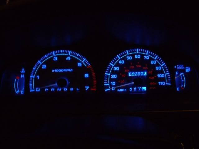
When I installed these I decided not to put in the white overlays at the bottom of the cluster, and this is what it looks like:
Anyway, once again great work! I permanently fastened my dimmer control/color switch behind the fuse panel door so that I could always get to it... never have to though! I purchased mine from that ProCarParts website. Highly recommended!
Oh and I just noticed... I installed these over 30,000 miles ago and have never had an issue! They're still glowin strong
I need to be more thoughtful when I install things so that I can help out the Yotatech community better... Anyway, I installed the exact same gauges some time ago and I just have one suggestion for you: get some blue LEDs to match! it looks pretty cool with the blue bleeding in around the base of the needles.When I installed these I decided not to put in the white overlays at the bottom of the cluster, and this is what it looks like:
Anyway, once again great work! I permanently fastened my dimmer control/color switch behind the fuse panel door so that I could always get to it... never have to though! I purchased mine from that ProCarParts website. Highly recommended!
Oh and I just noticed... I installed these over 30,000 miles ago and have never had an issue! They're still glowin strong
Last edited by pdyebrasil; 04-08-2009 at 01:08 AM.
12-18-2009, 08:10 PM
#16
Contributing Member
12-18-2009, 08:18 PM
#17
Registered User

Join Date: Sep 2009
Location: maine
Posts: 205
Likes: 0
Received 0 Likes
on
0 Posts
hmm, sorry it's late and i'm about to go sleep. i'm wondering, did you get new blue bulbs too? From the photos and quick reading, looks like all you did was overlap the the new gauges onto the original or did you just replaced them?
okay thats it, i'm going to bed, i cant think. i've been meaning to do something like this in my runner, just want to get the white setup with blue/red lights.... and change the bulbs for the heat control to match my shiny blue stereo too
okay thats it, i'm going to bed, i cant think. i've been meaning to do something like this in my runner, just want to get the white setup with blue/red lights.... and change the bulbs for the heat control to match my shiny blue stereo too
12-19-2009, 08:13 AM
#18
Thanks for the comps. Did this over 2 years ago and life has sort of taken over some things. I so what to get some blue LEDs to replace the factory lights.
These are overlays so I did not replace the gauges in the cluster. they fit right over the old gauges and I used the speedo/tac hold down screws to hold them in place. the edges are held in place by the gauge cluster. very simple and very nice looking. When I found these they were silver vice white. I like them better as they don't have the stark contrast that the white ones do. If you have any questions feel free to contact me.
These are overlays so I did not replace the gauges in the cluster. they fit right over the old gauges and I used the speedo/tac hold down screws to hold them in place. the edges are held in place by the gauge cluster. very simple and very nice looking. When I found these they were silver vice white. I like them better as they don't have the stark contrast that the white ones do. If you have any questions feel free to contact me.
12-19-2009, 07:52 PM
#19
Registered User
Join Date: Sep 2009
Location: maine
Posts: 205
Likes: 0
Received 0 Likes
on
0 Posts
okay, so you did replace the lights and just overlap the overlays on the old gauges. Mind telling me where you got your lights from? Also mind telling me which bulbs and how many i'll need? (also I want to replace the lights for the heater dash with the same colors) Thanks
I have a 98 limited 4wd runner and i'd like to do similar set up as yours but not put the white overlays on the bottom i think it looks better that way.
PS: has any one seen someone who has orange lights or all red? i havnt seen anyone who has that set up, if yall have... mind linking me to the thread or pictures? Thanks
I have a 98 limited 4wd runner and i'd like to do similar set up as yours but not put the white overlays on the bottom
i think it looks better that way.PS: has any one seen someone who has orange lights or all red? i havnt seen anyone who has that set up, if yall have... mind linking me to the thread or pictures? Thanks
Last edited by bvet4dog; 12-19-2009 at 07:53 PM.


