The Perfect Power SMT piggyback controller
 04-06-2005, 08:01 AM
#1
Registered User
Thread Starter
The Perfect Power SMT piggyback controller
This thread is to talk about a fuel/timing piggyback controller called the SMT-6 (and it's close cousin the SMT-7).
Many folks have been exposed to the FTC-1 ("Fuel/Timing Controller") from Split Second, and the SMT series is very similar to those boxes.
These controllers exist to be used with modern day computer controlled engines (like ours!) that don't allow the user to have clear access to adjusting the timing and fuel delivery. This can be useful when tuning your vehicle for maximum power, or torque, or different fuel grades, or to support additions such as a supercharger or water misting system.
First off, this is what we're talking about:
The SMT-6 and SMT-7 (click the pics for their associated home pages)


These boxes are designed to sit in front of your stock ECU and intercept signals from the engine (and associated systems) such as air flow metering, camshaft position and the oxygen sensor. The box is designed to look at this information and then modify it before the ECU sees it. This allows the ECU to make changes such that the ECU thinks that the engine is operating differently than it really is, and thus changing the fuel and timing parameters of the engine in real time. Through a Windows (and DOS!) application, the the user has the ability to lean out or richen the fuel mixture and advance or retard the timing.
To understand the SMT boxes, it's best to look at how the ECU makes it's decisions for setting fuel delivery and timing.
The ECU works from a table of numbers, one for each of fuel and timing. As engine parameters are read (A/FR, air flow, RPM, TPS, etc) the ECU uses this information to look at the table and derive a timing advance value and a "duty cycle" value for fuel. (side note... "duty cycle" is a reference to the amount of time that the fuel injector is allowing fuel to pass into the cylinder during the intake cycle. A "larger number" means that the "duty cycle" is longer, which means that more fuel will be feed into the cylinder)
Once the ECU has a number for timing and fuel, it applies those values until the next time that the engine parameters are read. This is the basis of modern computer controlled engines and in general, makes life a lot easier. We just put the key in the ignition, turn it, and start the engine. We want to go faster, and the ECU handles all the engine parameters for us.
But the headache in this system is that it's closed - if you WANT to get in there and advance the timing or lean out the fuel, you can't. There are companies (like JET) that for $400 or more will sell you a replacement chip for the ECU which modifies these tables, but the new table is still static. You may get a bit more power and/or torque, but the new values are a generalization for change.
Enter the piggyback controller.
Since the piggyback is modifying the information that the ECU sees, then it can control what "values" the ECU picks up and uses to control timing and fuel. The piggyback information is also setup as a table, and you cna set the values that are in the table "slots".
A picture is probably good right about now.
This is a pic of the SMT software showing the Fuel and Timing tables, or "maps".
(click for a larger pic)

Disregard other information on the screen, and only pay attention to the two tables of numbers.
The table on the left controls fuel delivery, and the table on the right controls the timing advance/retard. The green box in the lower left corner is the input cursor, and the two red boxes are the current values that the SMT is using.
The "input" to this table (i.e., what makes the red boxes move around) is a combination of RPM and a "deflection" value. The deflection value needs to be something that can relate engine RPM to engine load. Traditionally this is either Throttle Position or Air Flow. The combination of the two inputs is what lets the SMT pick a value to affect fuel and timing. In the example, it's showing a 36% deflection and an RPM of less than 946 (the RPM values are upper thresholds).
The scale for the deflection and RPM range is user defined. This allows for the SMT to be molded to the specifc engine and inputs. For example, this RPM range is set to work from 600 RPM to about 5800 RPM, or the reasonable parameters of our engines. My deflection input is the MAF, and the related scale of 28%-81% is set for how I've seen the airflow coming through the MAF. (side note, this was PRE supercharger! my scale is now 31%-97%)
To use the SMT, the user fills in these tables of values. Working with a A/FR meter or keeping an eye on Long Term Fuel Trim (LTFT) as you drive around will give you an idea of what to set where for the various fuel values. I'll babble more about tuning specifics in a later post.
Setting timing is "easy" in the since that you generally want to set as much advance as you can get away with before the engine starts to ping. This is a very loose method though, because you can't always "hear" ping ("knock") and it can be dangerous to let an engine ping for a long period of time.
So... I think that's about it for a first post into this thread. It's an introduction into the SMT series, a bit of theory on the ECU and how the SMT does what it does to fake out the ECU.
I'll babble more later on configuring and using the SMT to make various things happen with your engine.
Many folks have been exposed to the FTC-1 ("Fuel/Timing Controller") from Split Second, and the SMT series is very similar to those boxes.
These controllers exist to be used with modern day computer controlled engines (like ours!) that don't allow the user to have clear access to adjusting the timing and fuel delivery. This can be useful when tuning your vehicle for maximum power, or torque, or different fuel grades, or to support additions such as a supercharger or water misting system.
First off, this is what we're talking about:
The SMT-6 and SMT-7 (click the pics for their associated home pages)
These boxes are designed to sit in front of your stock ECU and intercept signals from the engine (and associated systems) such as air flow metering, camshaft position and the oxygen sensor. The box is designed to look at this information and then modify it before the ECU sees it. This allows the ECU to make changes such that the ECU thinks that the engine is operating differently than it really is, and thus changing the fuel and timing parameters of the engine in real time. Through a Windows (and DOS!) application, the the user has the ability to lean out or richen the fuel mixture and advance or retard the timing.
To understand the SMT boxes, it's best to look at how the ECU makes it's decisions for setting fuel delivery and timing.
The ECU works from a table of numbers, one for each of fuel and timing. As engine parameters are read (A/FR, air flow, RPM, TPS, etc) the ECU uses this information to look at the table and derive a timing advance value and a "duty cycle" value for fuel. (side note... "duty cycle" is a reference to the amount of time that the fuel injector is allowing fuel to pass into the cylinder during the intake cycle. A "larger number" means that the "duty cycle" is longer, which means that more fuel will be feed into the cylinder)
Once the ECU has a number for timing and fuel, it applies those values until the next time that the engine parameters are read. This is the basis of modern computer controlled engines and in general, makes life a lot easier. We just put the key in the ignition, turn it, and start the engine. We want to go faster, and the ECU handles all the engine parameters for us.
But the headache in this system is that it's closed - if you WANT to get in there and advance the timing or lean out the fuel, you can't. There are companies (like JET) that for $400 or more will sell you a replacement chip for the ECU which modifies these tables, but the new table is still static. You may get a bit more power and/or torque, but the new values are a generalization for change.
Enter the piggyback controller.
Since the piggyback is modifying the information that the ECU sees, then it can control what "values" the ECU picks up and uses to control timing and fuel. The piggyback information is also setup as a table, and you cna set the values that are in the table "slots".
A picture is probably good right about now.
This is a pic of the SMT software showing the Fuel and Timing tables, or "maps".
(click for a larger pic)

Disregard other information on the screen, and only pay attention to the two tables of numbers.
The table on the left controls fuel delivery, and the table on the right controls the timing advance/retard. The green box in the lower left corner is the input cursor, and the two red boxes are the current values that the SMT is using.
The "input" to this table (i.e., what makes the red boxes move around) is a combination of RPM and a "deflection" value. The deflection value needs to be something that can relate engine RPM to engine load. Traditionally this is either Throttle Position or Air Flow. The combination of the two inputs is what lets the SMT pick a value to affect fuel and timing. In the example, it's showing a 36% deflection and an RPM of less than 946 (the RPM values are upper thresholds).
The scale for the deflection and RPM range is user defined. This allows for the SMT to be molded to the specifc engine and inputs. For example, this RPM range is set to work from 600 RPM to about 5800 RPM, or the reasonable parameters of our engines. My deflection input is the MAF, and the related scale of 28%-81% is set for how I've seen the airflow coming through the MAF. (side note, this was PRE supercharger! my scale is now 31%-97%)
To use the SMT, the user fills in these tables of values. Working with a A/FR meter or keeping an eye on Long Term Fuel Trim (LTFT) as you drive around will give you an idea of what to set where for the various fuel values. I'll babble more about tuning specifics in a later post.
Setting timing is "easy" in the since that you generally want to set as much advance as you can get away with before the engine starts to ping. This is a very loose method though, because you can't always "hear" ping ("knock") and it can be dangerous to let an engine ping for a long period of time.
So... I think that's about it for a first post into this thread. It's an introduction into the SMT series, a bit of theory on the ECU and how the SMT does what it does to fake out the ECU.
I'll babble more later on configuring and using the SMT to make various things happen with your engine.
Last edited by midiwall; 03-29-2006 at 01:47 PM.
 04-06-2005, 03:20 PM
#2
Registered User
please babble some more!!
i noticed it said something about triggering - i figured this meant nitrous or WMI at various throttle/load positions - is that indeed the case?
Also how does this affect my engine - will it change the closed loop operation as well as open loop operation? The reason I ask is that I think 7mge injectors are a good swap provided you can tone down their output at WOT. The duty cycle level would drop during normal driving I THINK, but during WOT the ecu jumps to a set of fuel tables - I need to adjust those I'd think.
Also what about converting our 3vze to a MAF system instead of a VAFM? Im planning a 7mge vafm swap but even that vafm is about 30% smaller than the stock 3vze throttle body so converting to a MAF system would make the intake plenum the biggest restriction just behind the TB.... Thoughts?
Last edited by Bumpin' Yota; 04-06-2005 at 03:22 PM.
04-06-2005, 05:50 PM
#3
Registered User
Thread Starter
Originally Posted by Bumpin' Yota
please babble some more!!
i noticed it said something about triggering - i figured this meant nitrous or WMI at various throttle/load positions - is that indeed the case?
The 3rd table is generally there to support an extra injector. It works like the other two in that it will pick up a user defined value based on two inputs, RPM and the deflection input. This value is turned into a voltage that appears on a dedicated output line. That line is then usually routed to an injector controller or possibly straight to an injector itself. The net result is a continuously variable control of additional fuel, or water mist.
The switched output can be tied to a threshold following your deflection input, airflow, temp or RPM. This ouput is normally used for something like a non-variable water mist system where you just want to trigger an action and let it go at a set rate for as long as the input threshold is exceeded. For example, kicking in WI once the airflow has exceeded 85%.
Also how does this affect my engine - will it change the closed loop operation as well as open loop operation? The reason I ask is that I think 7mge injectors are a good swap provided you can tone down their output at WOT. The duty cycle level would drop during normal driving I THINK, but during WOT the ecu jumps to a set of fuel tables - I need to adjust those I'd think.
The "grey area" comes from looking at what the ECU's purpose is in closed loop. It's there to keep the engine running at an A/FR of 14.7:1, and in our engines, there's nothing you can do to keep that from happening. The purpose of the piggyback in closed loop is to help the ECU find 14.7:1 faster. Like I had said in that other link, depending on how far off the initial attempt is, the ECU may be able to find it quickly (a few seconds) or it may take a couple of minutes.
Now, you can use this "slow" nature to your advantage. The ECU doesn't have any real memory of the last time it visited a cell in the table, so when it hits a value, it applies that value (along with the offset in the Short Term Fuel Trim - STFT) and then starts looking at the A/FR. From that point it starts tweaking as necessary to get to 14.7:1. What this means is that you can drop values in the table that will make the engine run lean (or rich) for a while, but as you hold on that cell, then the ECU will start adjusting things.
Anyway... yes, if you are going to run larger injectors, then you'll quickly find out that the SMT is your friend. To make a global adjustment like this, there's a global fuel adjustment "Fuel Zero Calibration" where you can adjust the overall starting point for your fuel adjustments.
ref:

With larger injectors you'll want to push this negative which will globally remove fuel. Finding that initial spot will be interesting because with 305cc injectors I don't think the engine will even start if this is at "0".
So, you'll need to push it to say -5, try to start it and see what happens.Be careful now.. This also means that once you put the injectors in, you will ALWAYS have to run the SMT. Not usually a problem, but it's something to keep in the back of your mind.
Also.. if you're gonna run the 305's (or larger!) then you'll first want to drop in a Walbro 190. If you don't, then the added injector size isn't going to buy you much at WOT. You need to be able to keep the injectors well fed, and the stock pump can't keep up with the 305's.
Also what about converting our 3vze to a MAF system instead of a VAFM? Im planning a 7mge vafm swap but even that vafm is about 30% smaller than the stock 3vze throttle body so converting to a MAF system would make the intake plenum the biggest restriction just behind the TB.... Thoughts?
I can tell you that the SMT doesn't care what the source of the deflection input is. You'll end up adjusting the scale of the input to match what you see at idle versus WOT. The inputs on the SMT are rated to handle 0-5v signals, and in that regard you'll be fine.
In regard to the TB being your bottleneck, yeah, that can be an issue. To "fix" it can be expensive and complicated if you have to basically fit a completely new TB to the plenum. But, if you're close (say, 3mm or so) then a few minutes with a Dremel tool will make it happen. A couple of folks have bored out their TB (myself included) - it's not hard.
The net effect of doing this is minimal though... Outside of being able to say "yeah man, I bored out my TB" (which is kewl!) I dunno that I'd recommend spending the time on it.
Hope that helps! I'll start working up some more generic babble as well..
Last edited by midiwall; 06-10-2005 at 04:16 PM.
04-06-2005, 07:58 PM
#4
Registered User
The engine runs stoichiometric at WOT? Ideally that's where I want the max power at (WOT) and was wondering if and how this could help me get the most out of what mods I do have and will be doing.
At cruise, hitting stiochiometric sooner would definately be sweet mpgwise...
Does the SMT6 also monitor injector duty cycle in real time at cruise as well as WOT?
Also assume I go the route of a MAF and replace the VAFM. Does a MAF contain all the sensors that a VAFM does? I know the vafm has an AIT sensor and am 100% unsure about the MAF...
Last edited by Bumpin' Yota; 04-06-2005 at 08:00 PM.
04-06-2005, 08:20 PM
#5
Registered User
Thread Starter
Originally Posted by Bumpin' Yota
The engine runs stoichiometric at WOT? Ideally that's where I want the max power at (WOT) and was wondering if and how this could help me get the most out of what mods I do have and will be doing.
And yes, the SMT will definitely come into play at WOT. It LOVES to work in WOT conditions.
Here's a setup/config point...
The ECU figures out "WOT" by a bunch of information like TPS, airflow, vacuum, etc. The SMT doesn't see all that, so what you do is set the top of the deflection range such that the red cursor hits the last (rightmost) column when the engine is in WOT. You can watch for the "real" WOT with an OBDII reader that shows more than just the CEL codes, then note the deflection point and set that value-1 as your analog end point. That way, yoou'll be iin that last column when you're at WOT.
Once you figure out where WOT is, then you can use the last column as a "WOT" column. That's how most people set it up and it works out pretty well. There are some instances where it'll get faked out (lotso skinny pedal on a long uphill for example) but 9/10 times you're good.
Remember though that you could start bouncing off of the rev limiter at WOT. If you do, then the net result is that the ECU will lean out the engine and there's not a lot that you can do with the SMT to get it back in line without backing off the gas.
Another setup point... you'll want to aim for a A/FR of about 12.0 - 11.5:1 at WOT. It's rich, but The S/C'd 3.4L seems to love running there for max power.
At cruise, hitting stiochiometric sooner would definately be sweet mpgwise...
Does the SMT6 also monitor injector duty cycle in real time at cruise as well as WOT?
The logging that's referred to on the PP site is that it will log the values that it's using to feed the ECU. In a way, that's logging injector duty cycle, but it's a bit of a stretch to _really_ know what that time is.
If you're set on doing something like this, then you may want to look at something like an external logger. The Innovate Motorsports LM-1 is generally sold as "just" a wideband O2 sensor and display, but it's really a 6 channel datalogger in disguise. (actually, you can chain a number of them together for up to 32 channels of logging) The inputs to the logger side are voltage based and you could tie into one injector to watch how long the injector is "open", thus being able to compute the duty cycle.
Also assume I go the route of a MAF and replace the VAFM. Does a MAF contain all the sensors that a VAFM does? I know the vafm has an AIT sensor and am 100% unsure about the MAF...
Last edited by midiwall; 04-06-2005 at 08:23 PM.
 04-06-2005, 08:48 PM
#7
Registered User
Exactly a vafm, if even a 7mge one is still very constrictive when compared to the cross section of the stock TB opening...
Im making another post real quick to see exactly what the 7 pins are for on the 3vze AFM...
Im making another post real quick to see exactly what the 7 pins are for on the 3vze AFM...
Trending Topics
04-06-2005, 08:50 PM
#8
Registered User
Thread Starter
Originally Posted by Eric
can you dump the AFM? and run off other engine triangulation paramaters such as TPS, MAP, and RPM...
I guess you can rig something like MAP and feed it to the ECU, but remember that the ECU is scaled to think that the input is a MAF so if the MAP doesn't match the voltage curve that the MAF generate, then you'll have troubles.
Most folks end up just subbing in a larger MAF, and on our engines that choice is usually one from a Supra.
The other side here is that we're talking about a S/C'd engine. The S/C is gonna do a good job of sucking what it needs through the MAF no matter what the opening. For example, I know that I only lose about 1/2psi of boost when I close up my deckplate thus reverting a 4" hole to feed the intake with just a 1"(ish) hole.
04-06-2005, 11:38 PM
#9
Registered User
Join Date: Oct 2003
Location: Fresno
Posts: 191
Likes: 0
Received 0 Likes
on
0 Posts
I've seen alot of guys here and on other toyota boards get their terms mixed up...
an AFM is an Air Flow Meter...
the standard bosch item has a flapper door that is connected to a potentionometer at the flapper doors pivot point. this flapper door is spring loaded shut. engine vacuum sucks this door open. when the door moves the potentionometer moves either increasing voltage/resistance, or decreasing voltage/resistance.
here is a picture of a AFM on a miata
a MAF is a Mass Air Flow meter, from my understanding is also called a HFM or Hot Film Meter.... This unit is nothing more than a tube that has a wire that is stuck in the middle of the tube. the wire is heated, and when air passes over the wire, the wire is cooled (think of blowing on your finger when you burn it on the stove) the engine computer figures out how much air volume is passing over the wire by the amount of cooling that is taking place.
here is a pretty good picture of a MAF sensor, you can see the wire in the middle of the smaller tube

a MAP sensor is a Manifold A Pressure sensor. this monitors vacuum on NA motors and boost/vacuum on turbo/supercharged motors. the engine computer figures out how much air is entering the engine usually by the pressure differential from general atmospheric to monitued manifold pressure. (a barometric sensor will can be used to adjust atmospheric pressure for high altitude situations.
no picture of a MAP sensor since it would just look like a vacuum tube.
Now I don't see how my toyota is different from my BMW, they have the same POS AFM system and OBDI electronics. So with those similarities, I'll tell you what I know.
Many Many M3 guys have been sukkered into buying the split second MAF kit. this gets rid of the AFM and uses a ford MAF and SS gizmos to tune. If you look on SS site, you can see the kit they offer for the 1988-91 M3. this kit give good low end torque improvements, but still limits you to a 3 inch intake. This might not seam like a big deal to toyota guys, but on that model car, it came from the factory with 4 46mm throttlebodies.
anyways BMW was runngin alpha-N on the E30 M3 back in the late 80's when it was campaigning in DTM. alpha-N is basically the BMW term for running engine RPM=(N) and TPS=(alpha) into a computer to figure out how much air was intering the engine. this worked fine on a race car that spent most of it's time at WOT, however they were tunning on a two plane system, and thus it required constant tunning at each race track. if you trow in TPS and make it a 3d sytem then you can get a much more reliable/constant tune since it is hard to determing engine load on TPS alone.
many BMW guys are running what we still call alpha-N now on our M3's however it isn't true alpha-N like the race cars had. these units us an air temp sensor, a throttle position sensor, a manifold air pressure sensor, and engine rpm. from there the aftermarket unit computes these 3 or 4 parameters into a voltage that would equal what the old POS AFM would give at a certian RPM/load.
sorry if I'm speaking to the choir here, I have lots of links on ditching the AFM for BMW and Bosch electronics if anybody would like
an AFM is an Air Flow Meter...
the standard bosch item has a flapper door that is connected to a potentionometer at the flapper doors pivot point. this flapper door is spring loaded shut. engine vacuum sucks this door open. when the door moves the potentionometer moves either increasing voltage/resistance, or decreasing voltage/resistance.
here is a picture of a AFM on a miata
a MAF is a Mass Air Flow meter, from my understanding is also called a HFM or Hot Film Meter.... This unit is nothing more than a tube that has a wire that is stuck in the middle of the tube. the wire is heated, and when air passes over the wire, the wire is cooled (think of blowing on your finger when you burn it on the stove) the engine computer figures out how much air volume is passing over the wire by the amount of cooling that is taking place.
here is a pretty good picture of a MAF sensor, you can see the wire in the middle of the smaller tube
a MAP sensor is a Manifold A Pressure sensor. this monitors vacuum on NA motors and boost/vacuum on turbo/supercharged motors. the engine computer figures out how much air is entering the engine usually by the pressure differential from general atmospheric to monitued manifold pressure. (a barometric sensor will can be used to adjust atmospheric pressure for high altitude situations.
no picture of a MAP sensor since it would just look like a vacuum tube.
Now I don't see how my toyota is different from my BMW, they have the same POS AFM system and OBDI electronics. So with those similarities, I'll tell you what I know.
Many Many M3 guys have been sukkered into buying the split second MAF kit. this gets rid of the AFM and uses a ford MAF and SS gizmos to tune. If you look on SS site, you can see the kit they offer for the 1988-91 M3. this kit give good low end torque improvements, but still limits you to a 3 inch intake. This might not seam like a big deal to toyota guys, but on that model car, it came from the factory with 4 46mm throttlebodies.
anyways BMW was runngin alpha-N on the E30 M3 back in the late 80's when it was campaigning in DTM. alpha-N is basically the BMW term for running engine RPM=(N) and TPS=(alpha) into a computer to figure out how much air was intering the engine. this worked fine on a race car that spent most of it's time at WOT, however they were tunning on a two plane system, and thus it required constant tunning at each race track. if you trow in TPS and make it a 3d sytem then you can get a much more reliable/constant tune since it is hard to determing engine load on TPS alone.
many BMW guys are running what we still call alpha-N now on our M3's however it isn't true alpha-N like the race cars had. these units us an air temp sensor, a throttle position sensor, a manifold air pressure sensor, and engine rpm. from there the aftermarket unit computes these 3 or 4 parameters into a voltage that would equal what the old POS AFM would give at a certian RPM/load.
sorry if I'm speaking to the choir here, I have lots of links on ditching the AFM for BMW and Bosch electronics if anybody would like
04-09-2005, 06:29 PM
#10
Registered User
Join Date: Jun 2004
Posts: 273
Likes: 0
Received 0 Likes
on
0 Posts
Looong rambling post.
A few things yall might find interesting. Don't like the fact that you can't tune in closed loop?
The TPS signal o a 3vz-fe (DOHC car version) is only used to trigger open loop mode. What you can do, is take your orange output wire (it's a switchable ground...) and connect it to a relay with a voltage that corresponds to a high TPS setting. (say 4.5-5v even, measure your TPS signal to be sure, some things run on a backwards scale! Like a 3vz-fe AFM!!!)
Say you trigger the relay at 55% TPS (I would highly suggest triggering it at over 50% throttle...) and bam, instant open-loop and a wiiiiide swath of the tuning map will no longer be tuned out.
About the ECU tuning out in closed loop mode. I have found on my car, if you are tuning to get it BACK to stoich (14.7) if you don't exceed 10 to 20 in either direction, the ECU will not normally take the change out. If you are tuning away from 14.7, it will begin to tune it out nearly instantly once you pass 10 in closed-loop.
You can check OBD-I cars by checking the vF voltage.
0V = Rich mixture 11-20% from normal (ECU is leaning the mixture)
1.25V* = Slightly rich mixture 4-10% from normal (ECU is leaning the mixture)
2.5V* = Within 3% of the basic map
3.75V* = Slightly lean mixture 4-10% from normal (ECU is richening the mixture)
5V = Lean mixture 11-20% from the mixture (ECU is richening the mixture)
* are in the "normal" range.
That will give you a picture on what the stock ECU is doing to the fuel mixture. ( ECU speak, OK the AFM is saying X amount of fuel is coming in. The o2 sensor is saying the AFM is Y amount too far off. Let me correct this)
Woot for how stupid a 3vz-fe ODB-I ECU is! (the least caring/dumbest Toyota ever made probably. At least it's highly easy to trick into doing things.)
Between the vF data, and a cheap heated (but not wideband) o2 sensor thrown into the tail pipe, you can cheaply see what the A/F ratio & stock ECU are doing.
.1 17:1
.2 16.5
.3 16:1
.4 15.4
.5 14.9
.6 14.4
.7 13.8
.8 13.2
.9 12.7
.985 12.1
Is a general scale on a 0-1v o2 sensor. DO NOT rely on a stock o2 sensor mounted near the engine. Their voltage increases at the same rate with TEMPERATURE RISES as it does with less oxygen (rich environment).
I wouldn't tune a hi-po turbo off that, but for anything less, if you don't make power so fast you outrun the o2 sensor... Golden and cheap. (If it's off, it'll tend to be 1/2 to 1 A/F ratio to rich also)
BTW, A 3vz-fe can accept over 550cc injectors on a 255lph walbro without a CEL, or problem. (you're loosing resolution by that time however) If you do the trick to "bypass" the AFM (I.E. extremely large vacuum leak, keeping the AFM from opening as much, then making up the difference with your piggyback) it doesn't loose any accuracy doing it until you've hit the ECU ceiling. Which is well over 550cc size injectors. (720's work without a CEL, or showing a code in diag mode 1; 850cc and above however, might.) A 3vz-e might tune slightly less if I were guessing. It starts with 40hp less so... Probably starts with a lower AFM voltage also.
(3vz-fe idles at 4.2-4.5v, WOT at 130whp is roughly 2v-1.5v. It runs backwards! No AFM/MAF upgrade useful for us! 3vz-e probably get's the same part also)
That being said, I need some help, from any of you. Especially anyone that's tuned a 3vz-e.
At 3,000rpm, for no apparent reason, my ignition goes crazy. At anything but the *lightest* throttle to get it to 3000rpm it will miss fire, and go into heavy pinging, and very sever detonation. It is fine with the ECU handling the ignition.
yellow wire in
pink wire out
I'm doing 24 teeth
8 per fire
dwell = 0
mode = 10***
Positive in
Positive out
Low level input
Interlaced signal
Dedicated power (straight to batt)
Separate ground (chassis ground, not shared)
All un-used wires are grounded to avoid picking up stray EMI (Will try un grounding them later, idea someone had)
***
YES it IS a missing tooth signal, however!!! Instead of it skipping a wave-form. Instead of it missing a tooth, it has a double tooth. On the O-Scope when I was originally installing, instead of it "skipping" a wave, it holds the "missing" wave almost double the amount of time.
After a few weeks of trying everything with help, and some minor help from PP and bob, I discovered randomly that the smt-6 drove the signal perfectly in mode 10. Go figure... Missing tooth signal, but the SMT couldn't replicate the missing tooth. (at least from what we were trying! Ha tricky bastard!)
Anyone have the global settings for a 3vz-e, or have any ideas to the ignition problems? I'm scared... I've done a ton of stuff to a lot of engines, but the severity of the detonation is simply disturbing. I've heard engines that run smoother, while making less noise with a rod shoved out of the side of the block. (I'm not kidding!)
Last edited by Toysrme; 04-09-2005 at 09:07 PM.
04-09-2005, 06:53 PM
#11
Registered User
Join Date: Jun 2004
Posts: 273
Likes: 0
Received 0 Likes
on
0 Posts
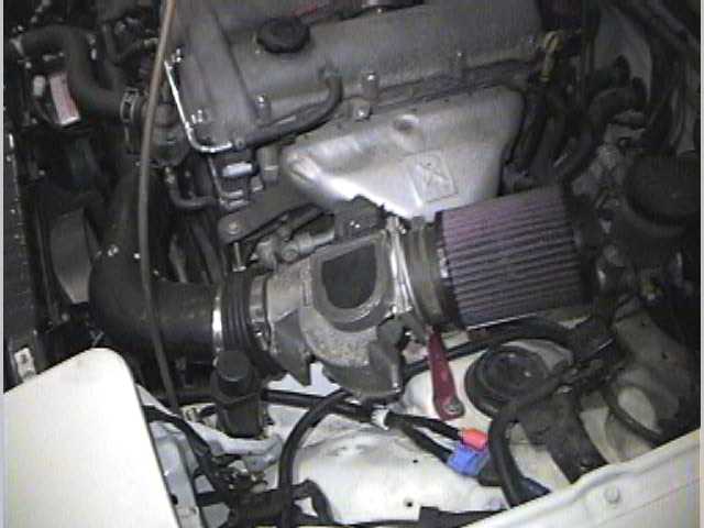
And to go along with what Eric was saying, here's what your AFM looks like.

I ripped the PCB completely out of it . Couldn't find the correct one from a junkyard for under $50, so I just rebuild the traces/pins on mine. Works like a charm now! (warning for anyone else. Toyota uses very low temperature soilder. *very* easy to melt it into puddles with a low temp iron)
I ripped the PCB completely out of it
. Couldn't find the correct one from a junkyard for under $50, so I just rebuild the traces/pins on mine. Works like a charm now! (warning for anyone else. Toyota uses very low temperature soilder. *very* easy to melt it into puddles with a low temp iron)
04-09-2005, 08:21 PM
#12
Registered User

Join Date: Jun 2003
Location: Vancouver, Canada
Posts: 943
Likes: 0
Received 0 Likes
on
0 Posts
Awsome another SMT thread
Good to see that people are still using the SMT units and most with more sucess then the huge SMT thread a while back.
I have accumulated over 40k km on my tacoma since the install of the smt6 and the s/c and have run into no problems whatso ever.
Well i would like to answer osme questions in regards what you can do with the unit as well...
To answer some questions about AFM/MAF removal, yes this is possible with the SMT6 as you can make the smt6 send the ecu MAP voltage signals that matched what the AFM/MAF used to put out at a certain load/rpm point. As you can see this will take a while as yuo have to log alot, but in the end you got zero restriction in your intake (issue for some not for others) and dont have to worry about loosing resolution.
The SMT7 that will be arriving shortly has a auto tune feature allowing you to remove MOST maf/afm systems without hte hassle of matching the voltage on your own. I should be reciving my test unit shortly and it iwll go into the Tacoma shortly after for testing. Once that is done the unit will be for sale on my site.
Toysrme,
Try to use a 1k resistor that is what i have used in the past and continue to do so....it has worked a couple times i needed it.
 04-10-2005, 05:45 AM
#14
Registered User
Originally Posted by Toysrme
That being said, I need some help, from any of you. Especially anyone that's tuned a 3vz-e.
At 3,000rpm, for no apparent reason, my ignition goes crazy. At anything but the *lightest* throttle to get it to 3000rpm it will miss fire, and go into heavy pinging, and very sever detonation. It is fine with the ECU handling the ignition.
yellow wire in
pink wire out
I'm doing 24 teeth
8 per fire
dwell = 0
mode = 10***
Positive in
Positive out
Low level input
Interlaced signal
Dedicated power (straight to batt)
Separate ground (chassis ground, not shared)
All un-used wires are grounded to avoid picking up stray EMI (Will try un grounding them later, idea someone had)
***
YES it IS a missing tooth signal, however!!! Instead of it skipping a wave-form. Instead of it missing a tooth, it has a double tooth. On the O-Scope when I was originally installing, instead of it "skipping" a wave, it holds the "missing" wave almost double the amount of time.
After a few weeks of trying everything with help, and some minor help from PP and bob, I discovered randomly that the smt-6 drove the signal perfectly in mode 10. Go figure... Missing tooth signal, but the SMT couldn't replicate the missing tooth. (at least from what we were trying! Ha tricky bastard!)
Anyone have the global settings for a 3vz-e, or have any ideas to the ignition problems? I'm scared... I've done a ton of stuff to a lot of engines, but the severity of the detonation is simply disturbing. I've heard engines that run smoother, while making less noise with a rod shoved out of the side of the block. (I'm not kidding!)
04-10-2005, 09:03 AM
#15
Registered User
Join Date: Jun 2003
Location: Vancouver, Canada
Posts: 943
Likes: 0
Received 0 Likes
on
0 Posts
Originally Posted by Bumpin' Yota
Could you explain what that all means to newbs like me on the smt6?
because it is a universal system there is lots of vairbles to play around with when setting them the SMT6 for the first time. The ones listed above are such varibles.
yellow wire in <--- This just lets us know that he is using the yellow wire to take the crank signal from the engine to the SMT6
pink wire out <--- this is the signal wire coming from the smt6 going to the ECU (after it has been modified)
I'm doing 24 teeth <---this tells the SMT6 what kind of pattern is setup on the crank wheel or disti wheel to let the ECU/SMT know at which point the engine is at currently. aka 240degree or 600degrees (so it knows when to fire/spark and what not)
8 per fire
dwell = 0 <---Unused....this is delay time for the coil to charge up while waiitng for the next spark. (as far as i know)
mode = 10*** <---depending ont he stup the SMT6 has MANY different modes to try...most of them wont work with our applications but it all depends what sensors are used on your engine. Different mode enable different modifications that can be done...like speed governor removal....transsmission shift points modification.
Positive in <---Sensors all positive polairity (simple terms)
Positive out <---Ditto above...so the SMT6 knows to output the samne thing as its recieving
Low level input <---Lots of toyota signals are very weak and this lets the smt6 know that it has to look "harder" for the input signals from the crank.
Dedicated power (straight to batt) <---SMT6 directly wired to batt...
Separate ground (chassis ground, not shared) <---has its own ground to prevent interference from other units.
All un-used wires are grounded to avoid picking up stray EMI (Will try un grounding them later, idea someone had) <---this works or not depending on the application....i normaly have them off and have them running on my 5VZ for 2 years now without a hitch!
Hope this helps!
04-10-2005, 11:04 AM
#16
Registered User
OOOOH so this "tooth" system on the crack works EXACTLY like the standyne injector pump coordinates its timig in realtion to the optical sensor on the cam shaft on the post '94 chevy turbo diesels!!
So what he is trying to do with a 'missing tooth' setup is retard the ignition? How many teeth are on the crank for the crank sensor? I'd imagine 1 tooth would give you X amount of retard or advance....
Am I correct or waaaay off base?
So what he is trying to do with a 'missing tooth' setup is retard the ignition? How many teeth are on the crank for the crank sensor? I'd imagine 1 tooth would give you X amount of retard or advance....
Am I correct or waaaay off base?
04-10-2005, 12:07 PM
#17
Registered User
Join Date: Jun 2004
Posts: 273
Likes: 0
Received 0 Likes
on
0 Posts
Still not running right, but I just duh'ed myself into putting two things together. (tho as you will see, doesn't change anything)
Our distributor is 24 teeth, but I keep having to interlace the signal (divide by two) because DUH ignition... Distributor... Camshaft... Camshafts all spin ats at 1/2 crank speed...
Such a tard!!!
(same thing for all the 3vz-e guys doing this later. Distributor is on the end of the camshaft. Timing data might be different but...)
On other notes, in order:
1) disconnected all the non-used wiring from their ground and split them back up
2) used the correct 1K ohm resistor (with the 24/8, interlaced settings)
3) changed to the "more correct, but exact same" 12 teeth/4tpf, non interlaced
4) noticed all other stock SMT-6 toyota wiring calling for a 1k ohm resistor were not running the low levle signal. tried turning low level input to off (2.5v trigger, instead of 100mv) (no NE signal generated)
So... After going 1-3, it runs the exact same as before.
Even tho it runs 0-3000rpm on mode 10, Guess I'll go back to trying mode 1, missing tooth. The reason I think this won't work is because there is one missing tooth(the double tooth i described above), per 24 teeth. While an entire firing cycle is only 12 teeth. This is more than likely why when originally setting the SMT up so many months ago, mode 1 refused to work.
04-10-2005, 12:31 PM
#18
Registered User
Join Date: Jun 2004
Posts: 273
Likes: 0
Received 0 Likes
on
0 Posts
Whore on! (thinking this through)
Duh's lead to more duh's.
24 teeth per turn, over 360* of rotation... Not 720. The smt is expecting the 720* part.
Multiply that by two! 48 teeth per turn, 16 teeth per firing, 2 missing teeth.
Assuming the signal is varrying a little bit, the ignition cut ona 3vz-fe is at 7100rpm. If the SMT is overshooting, or the ECU is over reading (My guess is the double tooth signal is confusing one, the other, or both).
Then I'm simply boucing very, very hard off my ignition cut, and detonating on a miss-matched ignition signal afterwards.
It also makes since it would run to 3000rpm on the extra advance we have... I proved long ago (when this was working before hah!) our engine can take large amounts of ignition timing advance before it begins to ping. (20-25* of advanceon 87 octane @ WOT, over 5000rpm)
Anyways... The RPM the ECU sees should half, and the SMT will probably read incorrectly, but reading incorrectly and working is better than reading the correct RPM, and not!
Bet it works when I go back outside LoL!
04-10-2005, 12:56 PM
#19
Registered User
Join Date: Jun 2004
Posts: 273
Likes: 0
Received 0 Likes
on
0 Posts
=)
Ya that was it, i forgot all about that LoL!
So just for a note... 3vz-e owners trying to install an SMT-6.
48 teeth
16 teeth per firing
2 missing teeth
mode 1 (missing tooth mode)
Ya that was it, i forgot all about that LoL!
So just for a note... 3vz-e owners trying to install an SMT-6.
48 teeth
16 teeth per firing
2 missing teeth
mode 1 (missing tooth mode)
04-14-2005, 08:29 PM
#20
Registered User
Join Date: Jun 2003
Location: Vancouver, Canada
Posts: 943
Likes: 0
Received 0 Likes
on
0 Posts
Originally Posted by Toysrme
=)
Ya that was it, i forgot all about that LoL!
So just for a note... 3vz-e owners trying to install an SMT-6.
48 teeth
16 teeth per firing
2 missing teeth
mode 1 (missing tooth mode)
Ya that was it, i forgot all about that LoL!
So just for a note... 3vz-e owners trying to install an SMT-6.
48 teeth
16 teeth per firing
2 missing teeth
mode 1 (missing tooth mode)
everything better now?


