fog light switch help
 09-25-2010, 06:03 PM
#1
Registered User
Thread Starter
iTrader: (1)
Join Date: Oct 2009
Location: Seattle / Bozeman, MT
Posts: 276
Likes: 0
Received 0 Likes
on
0 Posts
fog light switch help
I'm working on rewiring my Hella lights and decided to use the factory fog lamp rocker switches:
(Taken from a diff thread)
I've tried searching and this is the best info i found yet, but does the 3rd prong/relay prong output a +12 or a ground? I'm assuming +12.... but I really hope its a ground.
I'm working on a way to get the Hella lights to shut off with the rest of the normal headlights when the driver door opens. I'll have a writeup soon

 09-27-2010, 04:50 AM
#3
Registered User
Join Date: Apr 2006
Location: TX
Posts: 503
Likes: 0
Received 0 Likes
on
0 Posts
here is the clarification:
TOP: (-) ground || not sure what it's used for but maybe for the switch indicator
MIDDLE: (+) 12v input || use either "accessory" or "constant" source.
BOTTOM: (+) 12v ouput || this will trigger the relay
try this method configuration to get negative trigger to your relay:
TOP: not sure about this one.
MIDDLE: (-) ground input
BOTTOM: (-) ouput to relay
09-27-2010, 08:03 AM
#4
Contributing Member
Join Date: Mar 2003
Location: COTKU,Ontario,Canada
Posts: 11,334
Likes: 0
Received 0 Likes
on
0 Posts
In the first case the negative connection is used for the indicator light in the switch.
If it is a small incandesent bulb than you could connect a pos. source in the second case and have it work as normal. However if the light source is an LED (I suspect it is but IDK I've never taken one of those switches apart) than the light would not work since LEDs are polarity sensitive (ie they only work one way).
For this application you are better off with a positive switch set up anyway... with a neg. trigger set up if you have chaffing of the trigger wire and get a fault to ground the lights could come on and pos. drain the batt. A pos. trigger wire does not have that problem.
Don't forget to protect both the trigger wire source and lights with separate fuses... a small one for the trigger wire (it has almost no amp draw) you want this one so if you get a chaffing short to ground you don't burn up the dash [it can happen], and the larger one that came with the hellas to protect them.
09-30-2010, 07:56 PM
#5
Registered User
Join Date: May 2007
Location: Denver metro area-CO
Posts: 2,175
Likes: 0
Received 2 Likes
on
2 Posts
If I recall correctly what the diagram included with the switch refers to as top is actually the bottom. It's top as oriented in the diagram but actually the bottom of the switch if you were facing the switch from the front and looking at it.
So you could easily just have the top and bottom wires reversed....or not...
So you could easily just have the top and bottom wires reversed....or not...
09-30-2010, 08:13 PM
#6
Registered User
Thread Starter
iTrader: (1)
Join Date: Oct 2009
Location: Seattle / Bozeman, MT
Posts: 276
Likes: 0
Received 0 Likes
on
0 Posts
I never received any docs with my switches - i ended up testing the switches and found that the illumination is a conventional bulb - (non-polarity dependent). Using the picture above as reference, the bulb is between the top and bottom pins. Switching occurs between the middle and lower pin. Use this as appropriate.
If you want a switched ground, from the top, connect +12, ground, grounded output lead
If you want a switched +12, from the top, connect ground, +12, +12 output lead
If you want a switched ground, from the top, connect +12, ground, grounded output lead
If you want a switched +12, from the top, connect ground, +12, +12 output lead
Trending Topics
09-30-2010, 08:59 PM
#8
Registered User
Thread Starter
iTrader: (1)
Join Date: Oct 2009
Location: Seattle / Bozeman, MT
Posts: 276
Likes: 0
Received 0 Likes
on
0 Posts
Took about 30 seconds to find this on 4X4 wire...
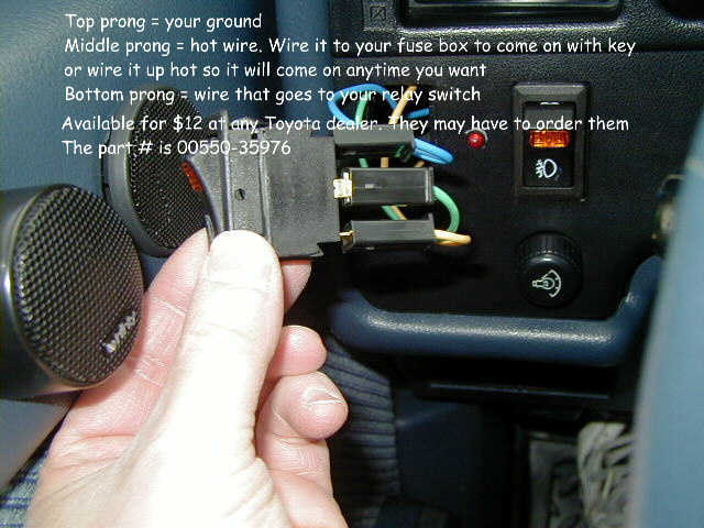
* Top prong should be connected to the ground wire
* Middle prong should be connected to the "hot" power wire
* Bottom prong should be connected to the wire for the relay


* Top prong should be connected to the ground wire
* Middle prong should be connected to the "hot" power wire
* Bottom prong should be connected to the wire for the relay

Thread
Thread Starter
Forum
Replies
Last Post
Johntom240
General Electrical & Lighting Related Topics
7
07-13-2015 12:18 AM


