When you click on links to various merchants on this site and make a purchase, this can result in this site earning a commission. Affiliate programs and affiliations include, but are not limited to, the eBay Partner Network.
Bah, the 3rd member isn't that heavy. it's much lighter than the front. I've done both. rear third is mostly just awkward. front third is heavy, awkward, and requires an extra set of arms. just make sure those arms aren't attached to a person with ADD. I spent the better part of 20 minutes bench pressing that front dif while a buddy looked for the bolts...then the ratchet...then the socket...then trying to get it aligned correctly...
yea....not fun.
you are right it isn't bad, my HF transmission jack has come in handy just as a place to catch a third. not really that heavy but nice to have something there.
had one get caught up a few years ago and release all of a sudden and wasn't quite ready for it and my finger felt awesome between the garage floor and the third
I'm reminded of Terry's comments when they poured his concrete pad, totally not jealous of his stove or nothing either..
Oh for a flat solid and DRY work surface.
We got dumped on with the white powdery cold stuff, should be below freezing all day then warmish before the next one. I need to go move snow to hopefully minimize the puddling when it starts to melt, and of course the north side won't get any sun so takes forever to go away and tends to melt then freeze into an ice puddle.
I went ahead and cut the stock fan shroud to allow for the 2" shorter radiator. I used the hack saw and kept all the trim, the hacksaw leaves the smallest kerf vs a cut off wheel and I can't find my shears think my roomie knicked them. Anyways I saved it all and made small cuts so it can be welded back to near normal. Right up till the end when it didn't fit and needed trimmed another 1/2 inch for the drain valve, I just bent it over and hammered it flat at that point I was over laying on my back trying to fit it around the AT coolant lines.
Took a full revolution off the turbo waste gate preload, Improved a little can give it more throttle before it cuts off the fuel. Might have another half turn before I run out of preload at which point the wastegate would never fully close.
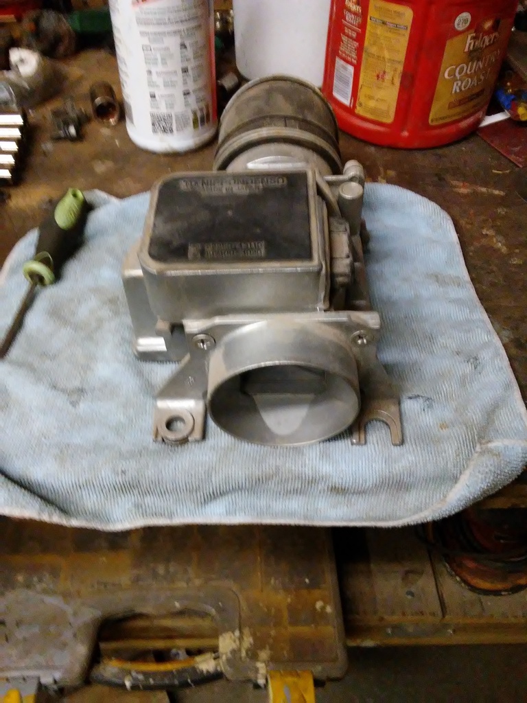
Took off the TPS to swap for the salvaged one. Noticed the salvage one was 90* wrong, and suddenly remembered there were two orientations of that plate on the end of the throttle body. Put the TPS back on and try to adjust it only to find my bad solder job vibrated loose at some point because I have no more IDL signal. With the TPS unpluged I can stomp the pedal to the floor and never hit fuel cut off, it ain't exactly hauling tail but It got up to a reasonable speed.
Looking into the dim headlights. The Right hand (P-side) lens has rock damage. I found they aren't sealed bulbs and already have E2/H4 housings. Great lets bypass the switch and jumper these right to ground and see how bright they could be, I got distracted and confused which side was High and Low I grounded the High side with the low beams running and blew the fuse. Swap out the fuse and try again, pictures don't do that upgrade justice at all.
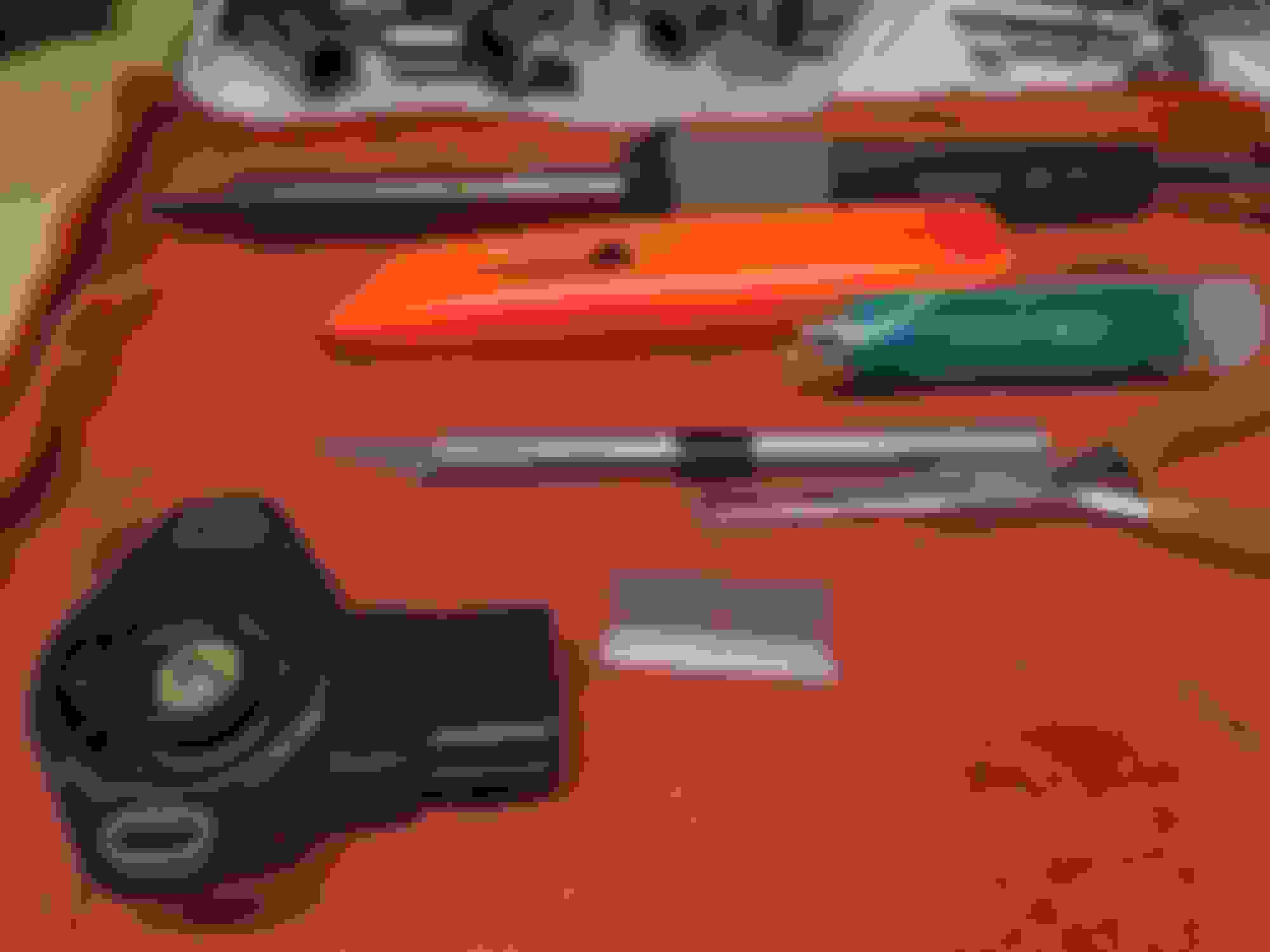
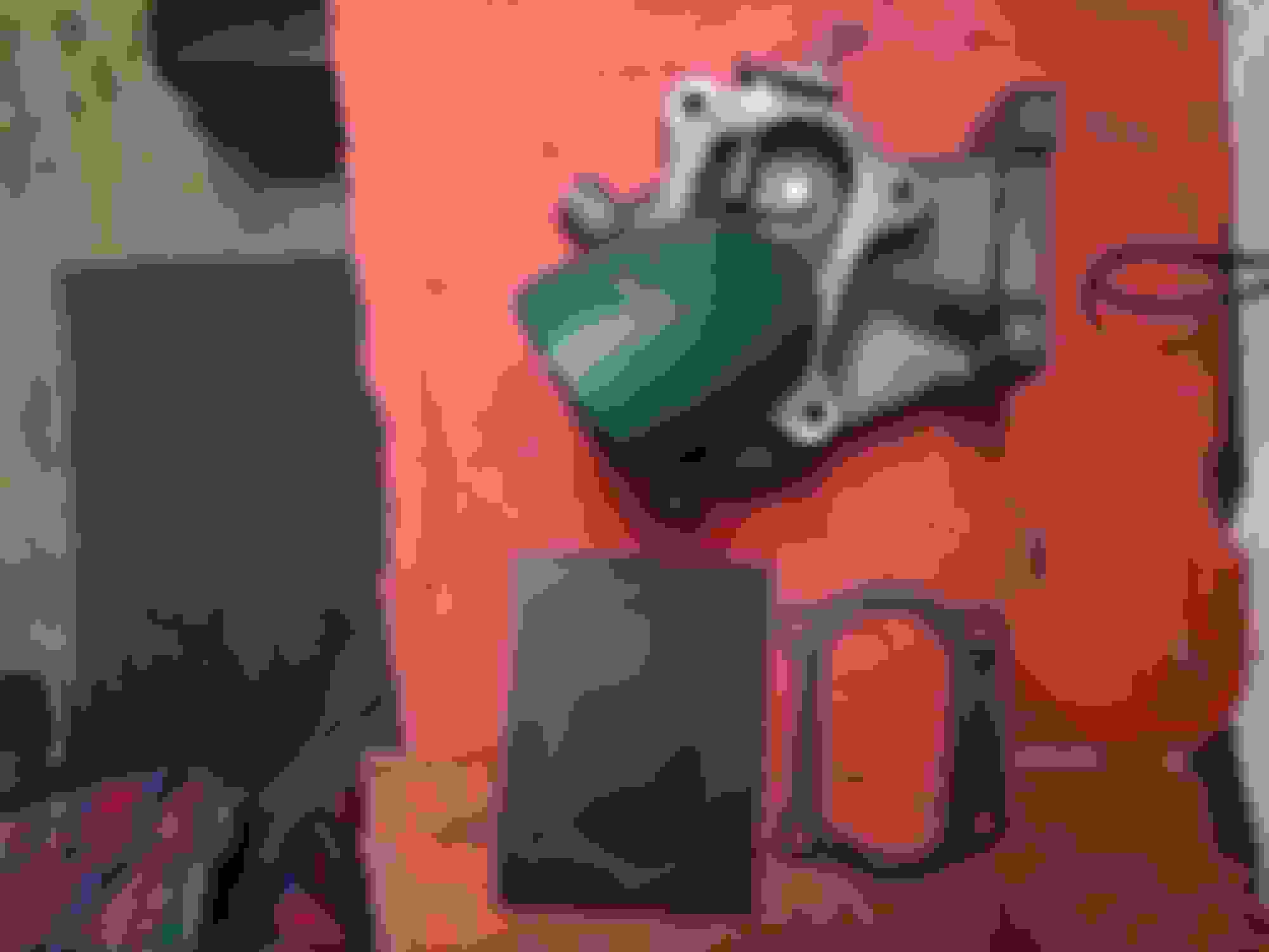
Had to hit it with the jump box to get it fired. Checking over the fan & shroud I see the belt is jumping around like a 3 year old full of soda pop. The alternator is loose. Pry bar against the PS pump and notice it flexed forwards. The bracket was loose on the front of the block, man who ever put this together doesn't deserve a pay check, completely missing the long bolt. Yeah it's up there in the "spares" picture and nobody caught it, it's the 10x1.25x ~120mm one.
On to the rear end. Drain the oil with my new 24mm socket, then spend five minutes wondering why I didn't have a rag handy not a single one. Scribe two sides of the driveshaft and a match mark on one corner/bolt. Break loose the four bolts, three of them are excellent still showing the factory coating( AL antisieze?) the third is kind of cruddy. Pry the shaft off the flange. Snapped pics of the color code on the pinion, and a "B" on the shaft(because I could..?). Pinion nut stake looks ok not restaked or reused. No notable wobble at the flange, was really expecting some thrust but I'm not a multi ton force either. Drained the catch pan and didn't find any large chucks of gear, found only two substantial flakes of metal on the drain plug under the sludge. My prior "oil sample" was done kind of in the dark and I've still not hosed the sand off the under side, what I got in the drain pan looked alot better. With the pinion not obviously loose, the fluid not being the 1/3rd sand 1/3 water I thought it had, topped off with I cant afford a new gear set and more tools. I decided to save the cash I'd spend on clean up and resealing, and just pumped some new oil into it. Painted the bolt shafts with fresh anti-seize and thread locked the threads. At this point I remembered I don't have another 14mm wrench and get to keep cranking on a partially spinning bolt and nut combo until the lockwasher bites enough it quits spinning. Cranked it down with a cheater wrench to ow ow owoouch tight. The noise has gone from "OMG what is that" to "I think that was the rear end noise only quieter". Between tires turbos and air leaks it just blends into the symphony now!
My floor jack leaks/doesn't hold, I think I've mentioned, but I managed to work a jack stand under the cross-member to hold the truck then the other one under the control arm to keep the tire off the ground. As I stand on the lug wrench I begin to think these might be a little over tight, two of them were put on by a gorrilla I guess. Slightly mushroomed but re-usable lug nuts. Installed 1/4" wheel spacer, on just the one side. Have equal spacing between upper control arm and tire on both sides now. Short test ride doesn't show any blatantly bad behavior. I'm not an alignment guy but think mine is a little weird and wonder if my frame is tweaked maybe. I happened to notice the adjustment cogs on the front side are both adjusted to the right(P)-side. If I'm not mistake that is the camber adjustment, why else would they adjust like that? The drivers side lower is pulled in(more arm clear), the passenger is pushed out (less clear).
Ok back to the code 14 overboost. I have turbo #2 disassembled, its the broken shaft one, and marked its exhaust housing for the orientation the new elbow/downpipe needs. It was siting on the bench next to #1, the toyota ct20, and I realized the opening for the wastegate isn't the same size diameter. I didn't take exact measurements, just eyeballed with a ruler. The Toyota CT20 has an opening of 0.75", the EMUSA has 0.50". Pop those diameter into a circle area calc and it will point out that increasing a circles diameter by 25% more than doubles the area, flow rate follows a similar model all things equal. I'm not certain how well centered #3's hole is but #2 would need hand-filed or milled to make it larger since it's offset from center a lot. I'm not really sure how I feel about it, rather how to proceed.. I should probably hog it out asap, I've heard figures of 22+ psi of back pressure behind the toyota ct20 and I can add preload if I need more to hold the gate shut.
Think that is about all.
Engine starts, Brakes hold, Gears shift, Wheels steer.
Needs an exhaust to keep Johnny law off my back, and a throttle sensor to put the grin back on my face.
(And of course all the little things) Test 4wd! Bumpers, blinkers you can see from the side, gnarly sheet metal firewall & fenders, pin hole in windshield, spider webbed moon roof(?), D-side door-card shredding at the rear corner, Loose seat-belt buckle, Perm gauge mount in center console, Cushion swap front seats, Plastic inserts/bits for doors (Dside for sure), Trans shift indicator label leaks light, Visors missing, Roof cover fabric missing, M U D everywhere, missing rear/tail panel dome-light cap and shell trim. Spare tire and rim, make sure the bottle jack works and the tool kit is in place.
Oh I got two small oil leaks, the gauge line on one side and the turbo oil drain is seeping some. The d-side hub still needs its index ball installed.
- This cap is sonic welded, or glued like the rest of the assembly.
- It has a lip, It needs to be cut off or attacked at an angle.
- Breached! The blade is thru, cut all the way to the ends. Socket extension made a good micro hammer.
- Fustrated yet, just cut the top side off and you can lever it out with a small screwdriver.
- Here is the cap upside down, well the important part. Note the lip, wear it's attached, and how much protrudes into the case.
- Circuit board attaches to housing lugs.
- Apply heat & use a tool to either pry up the housing lugs, or press down the feet on the circuit board, or your favorite desoldering tool.
- Donor housing lugs bent up with screwdriver.
- Another angle. Notice the feet on the circuit are S bent this gives them a little spring to manipulate they are still delicate
- Cut/Break off the tabs and remove the metal plate. (This is a 2nd gen 3.0 TPS, iirc)
- Cut away the hard green sealant. It will peal out with the exacto, it just needs to be removed from the housing to rubber junction and above if that makes sense.
- Flipped over, pressed out thru electrical cut out. Be gentle it is ceramic, no hammers.
- Sorry not the greatest photo. Above disassembled by gorilla, note the pads are dull. Lower, carefully disassembled.
- Gorilla method. Circuit board feet still attached to lugs. Again note the dull and rough texture. These are assembled using a re-flow oven and solder paste, and done poorly even on a circa 1980's Denso. It's probably something to do with the temperature of the conductive strips, but the problem is the solder-paste never fully liquefies or just leaves a crap grain structure. Good for us it means it separates along the solder joint it doesn't pull the conductor off the circuit board.
- Transplant patient.
- Flip side, 89452-28030
- Opened
- Patient, three of the spring feet detached, one more still in the housing.
- First two reattached, They have a claw on one end, that hooks over the board. Along the middle is a foot that seats into the hole in the pad on the circuit. These form a mechanical connection, if you need to fix/straighten a foot to make it seat DO.
- #3, Place into hole and cut outs, apply heat until the paste reflows (that's tech speak for melts), hold in place and remove heat. It's good as new
- Now make it better. GOB on the solder, until the hole is saturated now we have solder on both sides of the board.
- Can you tell I started on the right hand side, didn't do any warm ups, and don't do this all day every day. Ideally they should all look like the last one, smooth and shiny. Test each pin for continuity, next up is assembly.
- Carefully reinsert the circuit and rubber plug to the back side. Start the round side first, Leave the flat side proud of surface some and flip it over. You need to guide the circuit feet into the housing lugs with the exacto, you can also move the lugs in/out in the housing some. Apply heat to the lug near the plug inlet, apply the solder to the opposite end at the foot/lug juntion. When the solder melts remove the iron and let the solder harden. You should have the solder strand stuck to the lug touch it with the iron ABOVE the lug to free it up. You might find another technique works but this worked for me, the problem is the lug hole is huge and the pin is tiny..
- Resealed and curing. The rubber if it is in good shape and you don't crack the housing will keep it sealed. For good measure replace the green sealant, ideally an anaerobic like thread seal probably or gasket of your choice. Apply RTV to the cover plate and press into place. Fill the hole in the housing, If you were patient you can glue the plug back in. If you weren't and it or the housing cracks just use RTV there are not any sensitive materials inside.
Oreily's lists the same PCV for 85 different vehicles, everything from the 4cyl to 8cyl. It does NOT seal with pressure applied from the intake port side. I know because I have two now. Toyota parts sites list 3 part numbers. Will have to have one ordered with my VIN I guess.
TPS reinstalled and adjusted, I marked it when I removed it, then could't get the IDL contact and took it off swearing I bench tested it and I did checked fine it just went several degrees past where I had it marked. I did clean the contacts and the wiper areas.
Was going to test the VAFM and remembered I'm not sure if it's altered internally, been swaped for the larger plug n play one, or (I'm thinking this one) It's the larger VAFM with the 22r-te circuit board. Top cover plate and the connector are held with a clear silicone.
I need pictures measurements or casting markings to ID between the three or four variations the VAFM might be.
Idle air hose replaced with a loop of straight tube. fresh air intake blew off and barfed crankcase goo, replaced with a 22r-e section trimmed to fit.
AC vacuum switch has a broken wire at or inside the boot to the plug. AC doesn't have a belt or tensioner currently so no rush.
Topped off the PS fluid. It's probably going to need a new hose or clamp and cleaning. Seems like maybe the tensioner isn't lined up perfectly. A new bearing wouldn't hurt, but I'll check the tension and the mounting nut they like to back off and go missing.
Got three new crush fittings for the oil pressure gauge, and a 1/8 plug in case I can't get any of them to seal. I really hate pressure fittings we don't get along at all.
I'd like to be able to go over the shift points and verify everything still happens when it should but I have to manage the throttle to avoid that code 14 overboost
Cleaned up all the misc drips, leaks and splashes. I have the loose oil gauge, a puddle between the oil cooler plate and filter relocation plate, and a drip at the turbo oil drain wear it's not a hose barb but a threaded taper with a hose over it.
Still going to need the rear end work the noise is still there prominently at high speed engine braking. Hard to judge but it's maybe quieter at highway speeds now than it was at 50 before.
Got another 20 or so miles, 3 heat cycles. full tank of 91, and a clean windshield
Oh, I'm chasing vacuum leaks and idle fluctuations for anyone that wasn't obvious to. I'm not 100% sure the idle adjustment screw isn't moving either. I checked the timing and tweaked the idle after the TPS was in. Idle dropped to a stall while crossing train tracks, found the fresh air hose problem and wondered why the PCV valve didn't blow it's hose since I forgot to put the clamp on it.
Poking around the hot engine bay I found out that intake charge air is screaming hot, don't touch the tube kind of hot so an intercooler got added to the eventually list of the whiteboard on a three strikes ruling. I want to be able to touch the intake, i do not want rogue compressor wheels wandering by the throttle plate, and finally performance.and reliability.
Need to go over the horn circuit, can't be honking at hotties without a horn
Been enjoying following your thread. I have only worked on one turbo truck and it was not related to the turbo. I am actually not sure what I would need to do on a turbo. Anytime I get the chance to see some one working on one these I follow closely just to be aware of some of the issues that come with them. I like the details you go into, that does help on things as well.
Been enjoying following your thread. I have only worked on one turbo truck and it was not related to the turbo. I am actually not sure what I would need to do on a turbo. Anytime I get the chance to see some one working on one these I follow closely just to be aware of some of the issues that come with them. I like the details you go into, that does help on things as well.
I might go warm up the shed and take a look at the VAFM tonight. I'm not sure what I will find in there really. What I really wanted to find easily was some dimensions or casting marks that I could verify which it is. I found references on the 22rte site on some of the mods that are common. One common mod is to "tweak" the by pass screw which will effect the idle quality, this is the screw under the round AL plug. Mine has a small hole and wasn't bored out fully, but that doesn't mean it wasn't adjusted. If it's not marked and even if it is I really have no basis to reset it. I would like to assume these are set up by a grey-beard with meters and calibrated flow, but that's probably wishful thinking. The factory setup was probably assembly line type stuff, "fully insert screw back off X turns.", and the coil spring similar. I need those factory instructions or some reasonable simile. It is easy understand why the megasquirt conversion is so recommended. I'd have to agree an hour or so to install and some dyno time would simplify this a lot. If Santa wanted to drop me a MS and a wideband over the holidays I'd be obligated to document it :cheese:
It says this about the by-pass screw: "Tightening the screw beneath the plug makes the idle richer, loosening it leans the mix."
It says this about the vane spring: "Turn the gear wheel clockwise to lean the running mixture, and counter-clockwise for richer. "
HELP. I have a problem wrapping my head around that second adjustment
Reducing the bypass aperture puts more air on the vane so more VAFM signal translates to the ECU commanding more fuel. The throttle body idle aperture limits the air flow. This does result in a higher air fuel ratio. Turning the spring counter clockwise increases the tension, requiring more lbs/min of flow for a given vane deflection. How does this result in more fuel delivered for a given flow reading? Note just some made up numbers. If I have 25% throttle, 25% open vane, flowing 25 lb/min of air. vs 25% T, 25% V, but 50 lb/min. Given a fixed injector timing that is going to lean the mixture. The only way it makes sense to me is it relies on the oxygen sensor trim capability of the ECU where it will see the lean condition at the sensor and add fuel to compensate. There would be a point when I'd expect it to hit the trim limits and then throw the corresponding code. OR someone inverted CW and CCW.
One theory of the code 14 overboost says it triggers when the injectors reach saturation. To reduce the injector time the ecu needs a smaller VAFM signal per lb/min, so an increase in spring load. Another theory says 14 triggers when the rate of change of the VAFM is excessively large when compared against the Throttle and rpm signals. This one is from the "fuel cut elimination hack" by willcipher. There are two resistors identified on the circuit that control a high and low RPM cut off, on a 89661-35050 ECU these are labeled R208 (HIGH) and R204 (LOW). There isn't a lot of detail given on how these resistor values affect/effect(?) the limits, only that if you open the circuit the cut off will be disabled. A blind assumption but something adjustable would be a better approach, wiring in a trim pot should allow to keep the safety feature.
During my assembly I pulled the "intake pipe" from the pile of parts and had a world of grief trying to get it mounted to the turbo inlet and vafm outlet.
Deciding that just wouldn't do I got some couplers and an accordian hose and ran this instead. You can see my crankcase fresh air line to the VAFM, and the Turbo water line runs. we're still in a function over form mode, they might be made pretty later.
space-junk posted this photo
And I found THIS in the back of my 2wd the next day looking for something.
The one on top is the hacked up pipe I pulled off of my DD after I bought it. The lower one is the 22R-TE pipe. Somehow I mixed them up.
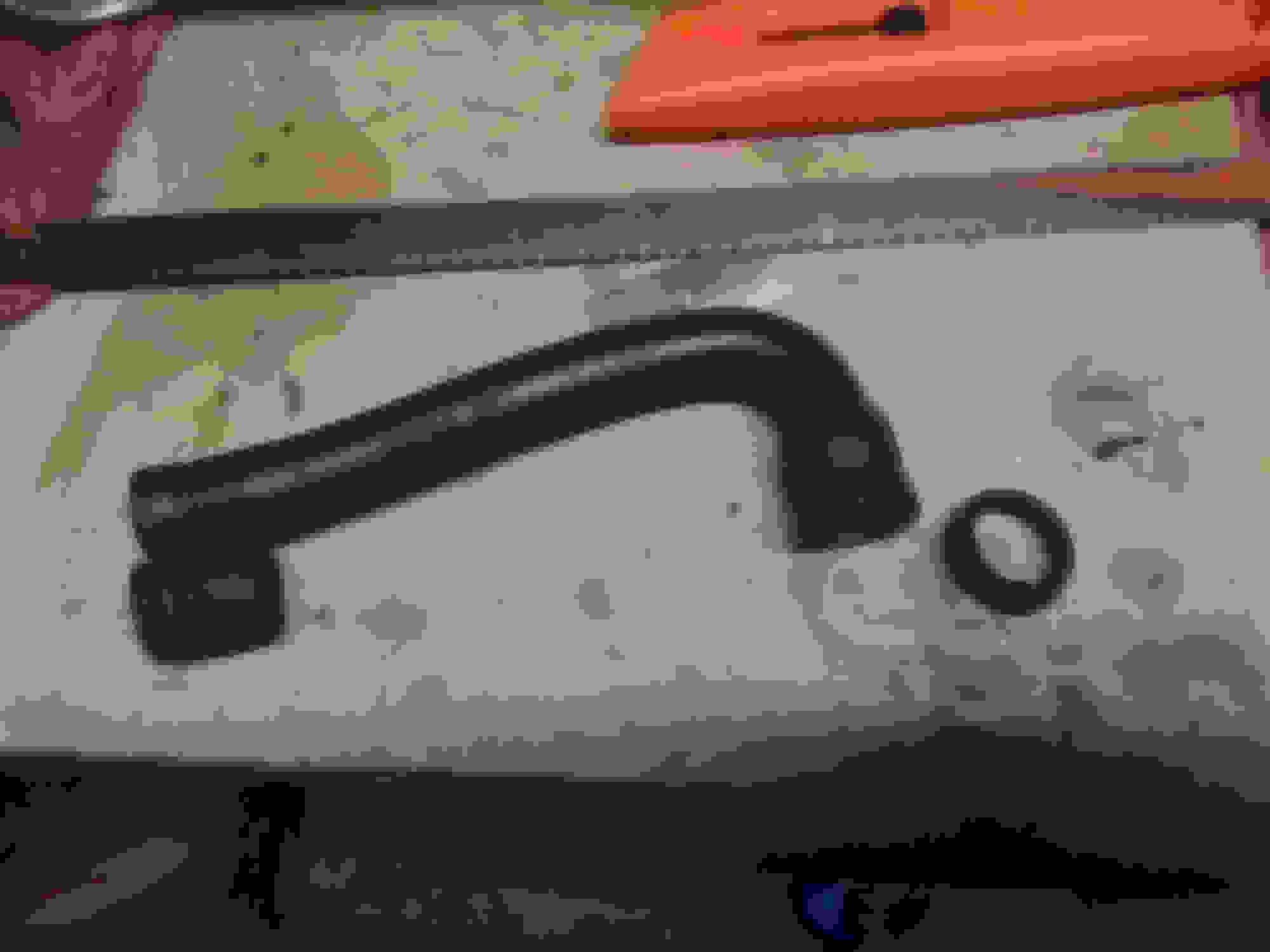
22R-E vs 22R-TE Crankcase ventilation fresh air hose. This is the forward line on valve cover into the flame arrestor. The non turbo version is slightly longer since it attaches at the plenum and the turbo one crosses over the intake tubing.
To use the 22R-E version it needs trimmed about an inch. Shown here is the turbo version, and the cut off bits from the 22R-E. (Ignore the little trim, I was just cutting off the cracked brittle parts of the donor)
Why, because I had the extra 22R-E one that was in decent shape and the bad one was barfing out the cracks. It's a 10-15$ hose from the dealer. I think it should have 90* hose barb personally, then you can use straight hose.
GUTS, Helper spring. Only contacts the mechanism while the fule pump contacts are open.
Two teeth tighter. I also tryed two teeth looser, and traced the retainer spring onto the cog for back up markings. I did not count the coils, but looks like three complete turns of the spring(TODO!).
The adjustment on this version really is simple the retaining spring will shift out of the way without loosening the screw. Using my thumb on the spring and a screwdriver inserted into the tooth next to the board I released the spring and levered the cog around.. Use the other side of the cog/board junction to lever the other direction.
Ok so I made the two clicks tighter adjustment and made a few runs, I can't say tighter was better than original, I should have done a refresher run with it at zero adjustment to calibrate the buttock dynometer. Then came home switched it two clicks looser and made another test run. Two clicks loose resulted in me turning around in the ditch and aborting.
It's hard to modulate the throttle, stay on the road, and read all the gauges in the instant it shuts off. I need a co-pilot, gauge lights that work, and a smaller scan area.
I have two boost gauges installed. currently they couldn't be positioned much worse unless I put one behind the drivers seat. Actually that would be an improvement maybe if I could use the rear view :cheese:. The PO had one installed, it's in an A pillar pod and plumbed into the gas filter on the rear of the plenum (actually Tee'd with iirc the cruise or something). I added the second one and plumbed it to a Tee in the wastegate line, it is temporarily mounted on the passenger side of the center console off that lower screw hole. I see on average 2 psi difference but have seen higher around 5 psi on the wastegate as the plenum nears the vacuum to boost transition. I am not sure how much of that is the gauges or actual pressure drop.
Kind of pining for ODB-II I guess.
Vehicle speed, RPM, Boost reading, and Throttle position, I need to track these four things at shutdown. It would be nice to have an electronic log of those prior and during the event. Vs from the air meter (Closed 0.5-2.5v, Open 5-10v), Vta from the throttle (Closed 0.1-1v,Open 4-5v), and boost from the dash gauge can be monitored at the ECU. Getting RPM and Spd need a pulse counter, Ne signal is a high-low transition, Spd is low-high. I probably have everything except a spare prototype board to assemble something with a PIC32, BUT I'm not setup to write code, out of practice, and electronics is just a hobby "Strike 3!". That's kind of overkill probably for what I want, it is the same cpu in the megasquirt. Not sure about the voltage levels if they are too high they need dropped or a higher voltage PIC. ... Dearest Santa!!....
CO, i love reading your posts as well, however i love your posts with pictures more!!! helps me better understand what youre talking about.
as for the VAFM, why not swap to the (85 i believe) supra VAFM? mostly plug and play.
Merry christymas, that intake tube post is for yall. I laughed my butt off over it and totally forgot to share it.
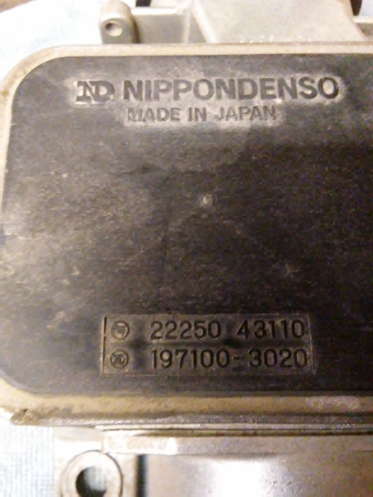
I wasn't actually sure it was the stock meter, the celica or some bastard child the PO put together. I'm pretty sure now the seals were original and it wasn't altered, and the 35050 part seems correct .. Lets see. Lakeland says 35020, epc-data says 35040, toyotapartsdeal.com says 35050 does not fit, it lists the 20 as the 22REC and it lists the 40 as the RTEC. What is the part number on yours out of curiosity?
Ok back to the code 14 overboost. I have turbo #2 disassembled, its the broken shaft one, and marked its exhaust housing for the orientation the new elbow/downpipe needs. It was siting on the bench next to #1, the toyota ct20, and I realized the opening for the wastegate isn't the same size diameter. I didn't take exact measurements, just eyeballed with a ruler. The Toyota CT20 has an opening of 0.75", the EMUSA has 0.50". Pop those diameter into a circle area calc and it will point out that increasing a circles diameter by 25% more than doubles the area, flow rate follows a similar model all things equal. I'm not certain how well centered #3's hole is but #2 would need hand-filed or milled to make it larger since it's offset from center a lot. I'm not really sure how I feel about it, rather how to proceed.. I should probably hog it out asap, I've heard figures of 22+ psi of back pressure behind the toyota ct20 and I can add preload if I need more to hold the gate shut.
Here are the unsorted various pictures that are missing.. (Actually probably backwards I see as I put in notes)
I've forgotten what size socket is being used for reference here I think it was the 10mm or 1/2", the Plug is a half inch pipe plug NPT male.
Turbo #1, my measuring method for using a ruler when you really want a caliper. Sight down one edge and line up the ruler. Left side on 4 here
Sight down the opposite side, and read the ruler. The key here is the rifle sighting of the walls to avoid an incoreect reading due to angle offset.
Right side at 4.75, translates to 0.75.
Turbo #2, measures up at 0.5". Not the shiney surface on the housing and the hole is off center.
Side by sides!!
More side by sides, this should be a 1/2" wrench.
Enlarging this hole will increase the exhaust by-pass for a given waste-gate movement, and should allow it to control the back pressure over a wider range of RPMS. "You can not have less boost than the minimum waste-gate setting". You can use the various boost control methods and "turn it up" but not down. The waste-gate spring is some where in the 7-12.5 lb/inch range (mentioned somewhere in the knock off literature) and has about an inch of travel. Pre-loading is the tension on the waste-gate arm/spring. My understanding is the preload is added to the spring rate and this is your minimum boost number. Currently I have the pre-load set to zero or maybe minus 1/2 turn, so it's either open or damn near open before the engine is even running and the only way to get less is a bigger hole or a lighter spring.
I was mistaken about the Microsquirt CPU it is a freescale cpu not a PIC32. Memory failure sucks, I looked that up awhile back and just got confused. There is another stand alone that has a PIC32 at the core but I don't remember who's.
I had mostly given up on my logging desires. Like I mentioned there is some setup required for writing code and producing prototypes that I don't like doing. On top of that I still have an intricate electronic setup on my bench with little to no documentation I haven't wanted to move. It's I think 1 pic running pbasic to bootstrap the 2nd pic with the picprogramer firmware to flash the 3rd which could have any number of projects running on it. Might be a voltage level converter in there somewhere. Like I said it's not well documented and I haven't wanted to break it, what ever it was I have it setup for..
So anyways. I have a couple demo boards I hadn't even thought about. One is a freescale, I've never taken out of its package.
Somewhere here I have one demo board that I have atleast done the introduction on. It's not automotive rated iirc but it has on board wifi which could be combined with an Android app for a dashboard.
Awha here we go. This one has wireless.
This one I've used, and I guess I liked it.
because I have more than one. Well I tried to get a picture of the specs but the cam on this tablet sucks..
Looks like finding the documents for the Cortex board is going to be hard maybe. The board seems ideal out of what I have, it has Wi-Fi and four analog to digital inputs.
OK I've done gone and gave myself a head ache squinting at data sheets. Probably best to throw an Arduino at it if I want to log this stuff..
:grin; You first! Honestly I would have already ordered something if cash wasn't a concern. I probably don't want to compare the available budget vs todo. I have that second turbo engine with the bad cam. Depending how this all turns out it will end up in the mini truck with a LSD, stand alone EFI, the 22R-E head, the fuel upgrades and a street tune on the dyno. I think I added it up to around 3k in parts, so budgeted 4-5k and was thinking to start in may. My budget has been reallocated, so maybe more like April 2018.
Google shoping lists that haltech for ~420$ from CARiD, that is the same as the 42pin denso DIYpnp megasquirt. The first doesn't have a harness or anything, the second is 8hours of beer drinking I mean soldering and should plug in and start up.
Alright so my mother asks me how it's going with the Toyota like she always does. She might not follow everything but a lot of it she understands or reminds her of some story that relates somehow. Like my PCV, she remembers who changed hers and explained why it was giving her bad gas mileage. 35 years ago! Anyways so i tell her I'm still getting the overboost code and have been looking to take samples at the ECU. "Why don't you just use a couple volt meters", she says. Thanks MOM! Talk about over engineering a simple problem. So <10$ over at harbor freight will handle the Vs and Vta and zip ties to rig it all up to video.
I plan to go over the TPS and VAFM electrical tomorrow if the weather permits. So resistance and voltage checks. I suspect I will find something in the TPS like it not reading the full range, or a badly baked wire on the air meter side.
I used the "that's good enough" method for tps adjustment not the FSM so it's off enough I want it better maybe. I can't believe I went and looked this up. One degree is around 1.11% of a 90* throttle plate movement. The stop plate arm is between 25-50mm. The FSM gap is 0.43mm, translates to about 0.5* of dead space @50mm. We come off Idl at 0.83mm, which loses another 0.5*. Now we're down to 89* of throttle plate, One degree is now 1.123%. The average error between good enough and the manual is 0.53 - 0.47 = 0.05mm = 0.056393* / 89 x 100 = 0.063%... Ok maybe that is not TOO terrible, but I could have messed up the math. I'm not 100% sure there is 90 degrees of movement, and that arm is actually shorter than 50mm.
Anyone care to speculate, or enlighten me, why the throttle signal voltage is listed as 0.1-1.0v Min and 4-5.0v Max. Does that correspond to the ecu voltage range of 10-14V?
I have an 82 Supra meter. It is 197100-3020. I pulled it off a one owner 82 Supra. A kid was texting and driving and rear ended her. I dont know if it is the same for the turbo or not but it is for Supra. I know it can be an upgrade for the 22re. I am not trying to make a sale but I know how hard these can be to find and if you really need it, I will sell it to you for cost that I have into it and shipping. PM if interested.
82 Supra part number and I think it is the bottom number everyone refers to.
Not sure if you tell by the picture but they do have a bigger bore then the standard 22re.
 12-18-2016, 11:25 AM