Dmarsh4X4's OM617 swap to 1988 4Runner
 11-17-2011, 09:16 PM
#1
Registered User
Thread Starter

Dmarsh4X4's OM617 swap to 1988 4Runner
Well I have been looking for a fourm to post my swap and this one seems to be the best. I have always wanted a diesel 4X4 and it looks like the only way I could afford one is to build one my self. Originally I was thinking of putting a cummins in my suburban and still probably will at some later date. I have always loved Toyota 4X4 and have had several of them over the years, So when a friend at work said he needed to git rid of his old 4Runner and I could have it if I wanted to pick it up, thats when this swap started. I have researched this swap for some time now across different vehicles and taking what I think are the best ideas and putting my own spin on things. I will be trying to make this swap bolt in with little or no major modifications to the vehicle, and if every thing is good after testing on my vehicle, and there is enough intrest I could be persuaded to make the seperate componets or kits available for sale.
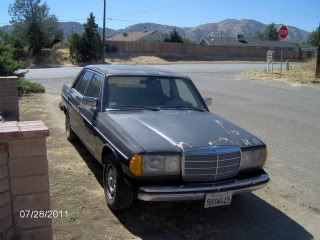
The Donor 1985 300D Turbo
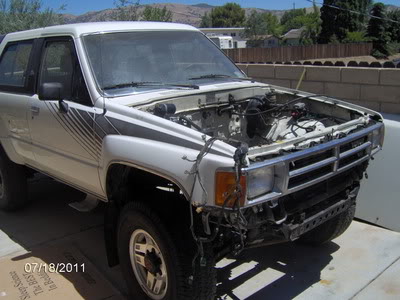
My Free 1988 4Runner
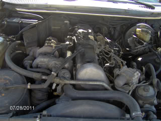
The Motor
I will post more of what I have completed on my swap tommorrow, I am hoping some of you might find helpfull.
The Donor 1985 300D Turbo
My Free 1988 4Runner
The Motor
I will post more of what I have completed on my swap tommorrow, I am hoping some of you might find helpfull.
 11-18-2011, 05:18 AM
#2
Registered User
Thread Starter
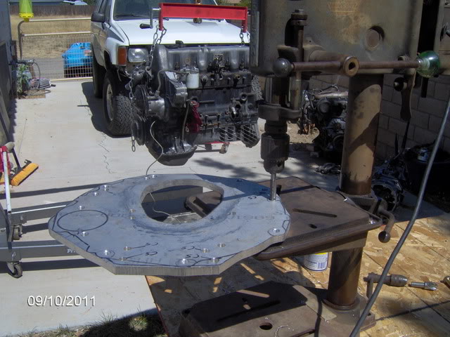
The two most difficult parts of this swap (and most expensive) are the flywheel and adapter plate. Here is how I did mine.
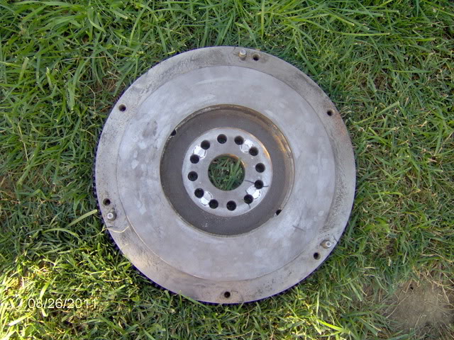
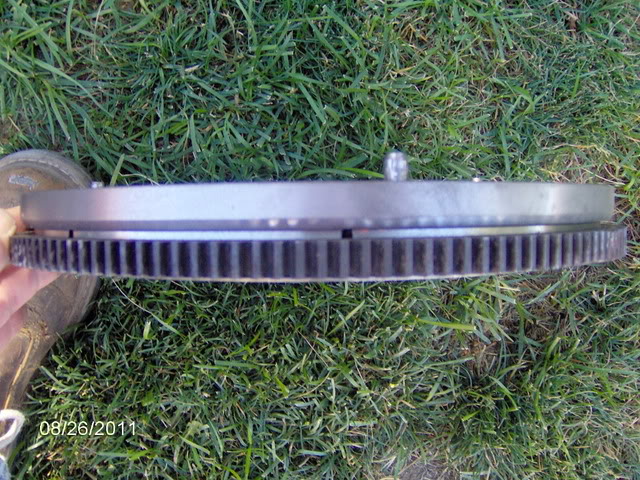
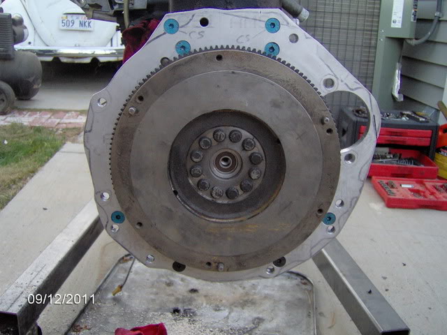
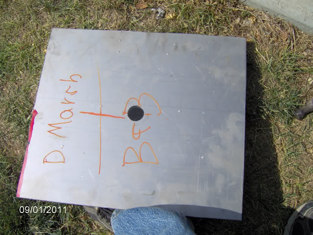
The flywheel is the Toyota 6 cylinder, 4 of the existing holes match up to OM617 crank pattern you just need to open them up a size or two, then I turned some round stock on a lathe to make 4 pluges for the other holes and tack welded in place ( you can see the welded plugs in the picture). Then on a mill I drilled the remaining 8 holes. A hole drill guide could be used on a drill press to do this also. If any one is intrested in a drill guide let me know, I could whip some up.
The flywheel is the Toyota 6 cylinder, 4 of the existing holes match up to OM617 crank pattern you just need to open them up a size or two, then I turned some round stock on a lathe to make 4 pluges for the other holes and tack welded in place ( you can see the welded plugs in the picture). Then on a mill I drilled the remaining 8 holes. A hole drill guide could be used on a drill press to do this also. If any one is intrested in a drill guide let me know, I could whip some up.
11-18-2011, 06:38 AM
#3
Registered User
Thread Starter
All the swaps I have seen so far use the matching starter for what ever transmission is used (Jeep, Chevy, Toyota ). From the other Toyota swaps I have seen, I know the Toyota starter causes issues with the exhaust down pipe, so I went with the Mercedes stock starter. The ring gear on the Mercedes flywheel is slightly smaller in diameter than the Toyota so it would be an easy swap. I removed the ring gears from both flywheels gently with an air chisel, you could also support the flywheel ring gear side down and heat the ring gear and it will fall right off. I then machined down the Toyota flywheel in a lathe to match the Mercedes, heat up the Mercedes ring gear to around 250 deg. and drop it in place. ( If any one is intrested when I pull my motor for final assembly I can get more pictures and dimensions.)
 11-19-2011, 05:29 PM
#6
Registered User
Thread Starter
Here is how I made my adapter plate, the hardest part was trying to figure out how to center the trans input shaft to the pilot bearing, this is what I came up with.
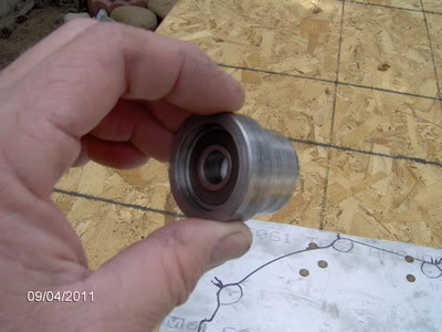
I used a hole saw to put a hole in the center of my plate the size for the small diameter of pilot bearing adapter to fit in ( I think it was 1 1/4")

You will use the pilot bearing adapter to center in the Mercedes crank. using transfer bolts in the back of the Mercedes block (I made mine on a lathe but you could probably make them on a drill press with a file.)
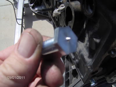
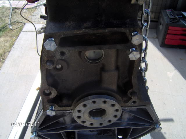
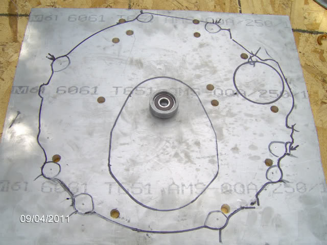
After drilling the adapter plate, to get the two dowel pin locations, I used the stock Mercedes motor to trans adapter and lined up all the holes in the two plates using drill bits and what ever I had that was a tight fit, I drilled through the dowel pin holes. Now the Mercedes patern is centered to the crank. Next post I will show how I centered the input shaft to the Toyota bell housing pattern.
I used a hole saw to put a hole in the center of my plate the size for the small diameter of pilot bearing adapter to fit in ( I think it was 1 1/4")
You will use the pilot bearing adapter to center in the Mercedes crank. using transfer bolts in the back of the Mercedes block (I made mine on a lathe but you could probably make them on a drill press with a file.)
After drilling the adapter plate, to get the two dowel pin locations, I used the stock Mercedes motor to trans adapter and lined up all the holes in the two plates using drill bits and what ever I had that was a tight fit, I drilled through the dowel pin holes. Now the Mercedes patern is centered to the crank. Next post I will show how I centered the input shaft to the Toyota bell housing pattern.
Last edited by dmarsh4x4; 11-22-2011 at 09:11 PM.
11-19-2011, 07:02 PM
#7
Registered User
This is a pretty helpful thread for finding what holes to use and to not use, when you're drilling through the mercedes stock adapter plate into your new adapter plate
http://www.pirate4x4.com/forum/showt...=645413&page=3
http://www.pirate4x4.com/forum/showt...=645413&page=3
Trending Topics
11-19-2011, 07:43 PM
#8
Registered User
Thread Starter
Thanks pyrojoe, I have seen that post early on in my saerches for this swap, I even started making my adapter like that one, but even after cutting the thickness of the stock Mercedes plate as thin as possible it was still to thick , at a little over 1", the input shaft of the trans would not even be near pilot bearing, and there was not a easy way to determine crank center, to line up Toyota bell housing bolt pattern
11-19-2011, 07:58 PM
#9
Registered User
I'm not trying to use that adapter plate, I just meant that you could tell with that thread, which holes you don't need to transfer to your new adapter plate. It would sure make life easier if we could use that plate though ha
11-20-2011, 07:00 AM
#11
Registered User
Thread Starter
Thanks RBX, I looked through your thread last night and it is quite impressive, I am shure to be using some of your ideas later, especially on the interior.
11-20-2011, 08:02 AM
#12
Registered User
Thread Starter
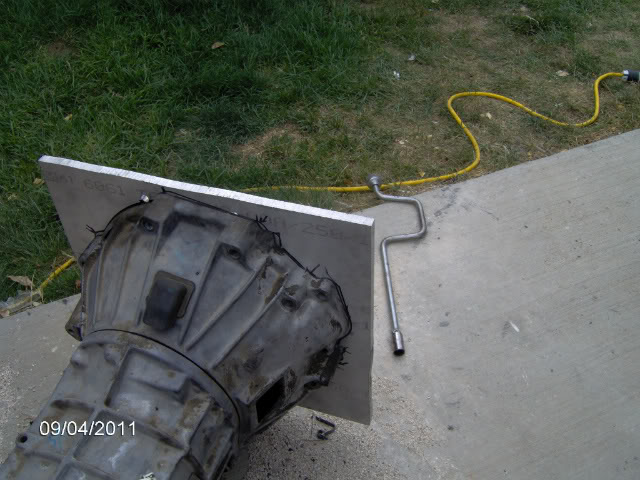
For centering on the bell housing I used the same aproach using the pilot bearing to center everything on the intput shaft.
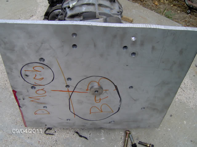
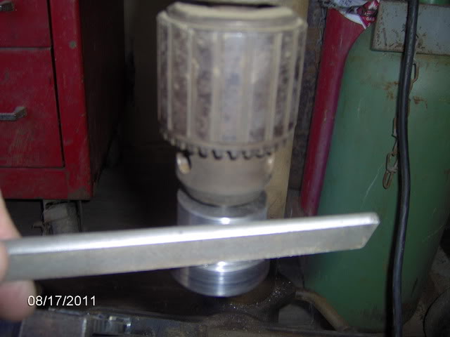
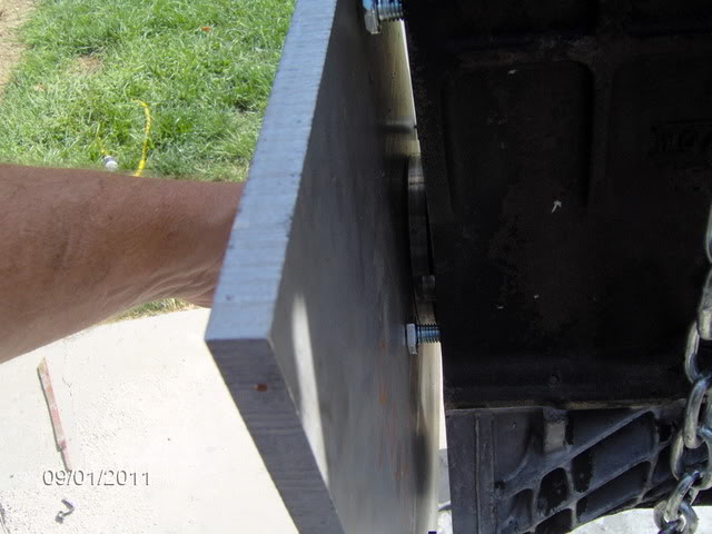
I leveled the trans side to side across the shifter openings, then leveled the plate across the two top holes previously drilled for the Mercedes motor mounting, this will give you 0 degeres clocking on the trans. The input shaft has a little play in it so I made a mark on the plate at the top of the trans with the weight of the plate pulling the input shaft play down, then moved the plate up and made another mark, the middle between the two marks is center of the input shaft play, this is where you want to clamp your plate to the bell housing.
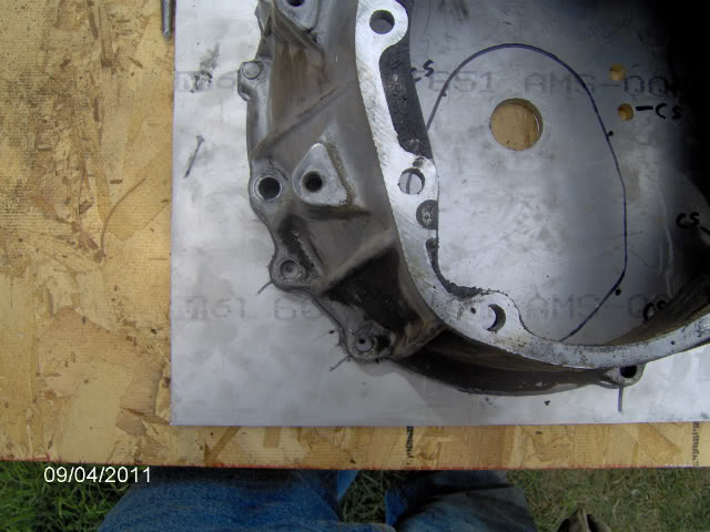
At this point I drew a tight outline around the trans and transfer punch the holes, the holes on the trans are tapered quite a bit, (larger on front of bell housing) making it difficult to line up the punch. After the holes are transfred I removed the bell housing and lined it up on my outline and visualy checked that my punch marks lined up centered in the holes, made any adjustment needed, I cut out the plate, I used a jig saw for the hole in the center, I had access to a band saw and used it for the outside then drilled and taped the holes.
An easy way to keep your tap square is to start the tap in the drill press.
I will post locating the starter next.
I leveled the trans side to side across the shifter openings, then leveled the plate across the two top holes previously drilled for the Mercedes motor mounting, this will give you 0 degeres clocking on the trans. The input shaft has a little play in it so I made a mark on the plate at the top of the trans with the weight of the plate pulling the input shaft play down, then moved the plate up and made another mark, the middle between the two marks is center of the input shaft play, this is where you want to clamp your plate to the bell housing.
At this point I drew a tight outline around the trans and transfer punch the holes, the holes on the trans are tapered quite a bit, (larger on front of bell housing) making it difficult to line up the punch. After the holes are transfred I removed the bell housing and lined it up on my outline and visualy checked that my punch marks lined up centered in the holes, made any adjustment needed, I cut out the plate, I used a jig saw for the hole in the center, I had access to a band saw and used it for the outside then drilled and taped the holes.
An easy way to keep your tap square is to start the tap in the drill press.
I will post locating the starter next.
 11-20-2011, 10:00 AM
#15
Registered User
Thread Starter
Yeah real cool, 40 deg. with chance of snow later LOL. Shop is a little messy right now.
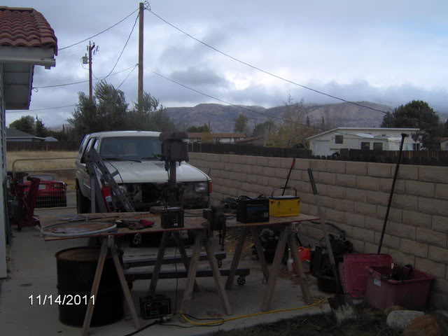
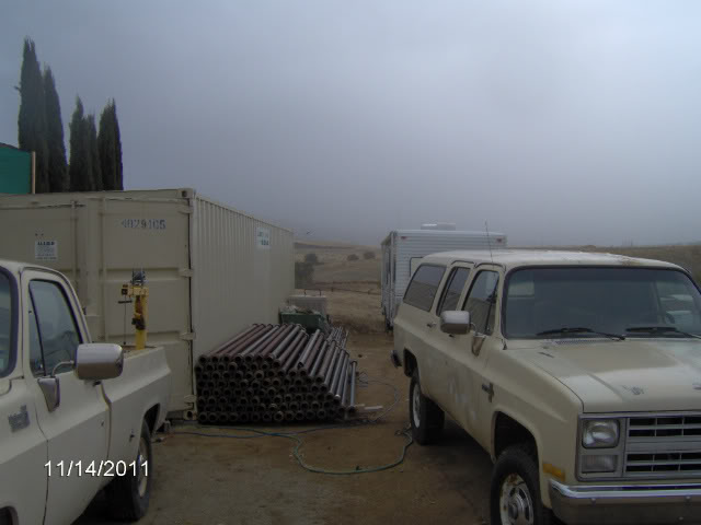
We recently moved here and my shop is still in progress. I need to pour some concrete and put up my metal building attached to the storage container. The container will house all the machine shop equipment, lathe, mill, tig welder, tools and storage, the mig welder, tube bender and two post lift will be in metal building.
We recently moved here and my shop is still in progress. I need to pour some concrete and put up my metal building attached to the storage container. The container will house all the machine shop equipment, lathe, mill, tig welder, tools and storage, the mig welder, tube bender and two post lift will be in metal building.
Last edited by dmarsh4x4; 11-20-2011 at 10:01 AM.
11-20-2011, 12:03 PM
#16
Registered User
I'm anxiously awaiting the moment you drop the motor in. I took some measurements this morning, and boy it's gonna be tight. Everyone else that's done the swap has cut their front support bracket just to fit everything behind the radiator. Was supposed to be 70 here yesterday..... it was 38. Still shooting paint anyways lol. Do you have any idea yet what you'll be doing for alternator/power steering pump/ac compressor?
11-20-2011, 08:15 PM
#18
Registered User
Join Date: Apr 2011
Location: Sedalia, MO
Posts: 317
Likes: 0
Received 0 Likes
on
0 Posts
Dmarsh- You sir are a genius! I tell you what I was nervous as a whore in church about doing that adapter plate but you have calmed my fears to say the least. Best of luck on the shop and the build.
11-21-2011, 06:38 AM
#19
Registered User
Dmarsh,
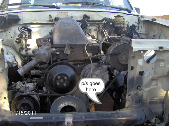
I saw your reply to pyroJoe's thread about swapping the A/c And Alt....can you give a few specifics about the a/c compressor bracket mount adapter for all the kids playing along at home? Also, you mention you are relocating the alternator to the where the p/s was, so is the p/s steering going to live low on the block like the stock MB a/c?
Thanks
11-21-2011, 05:03 PM
#20
Registered User
Thread Starter
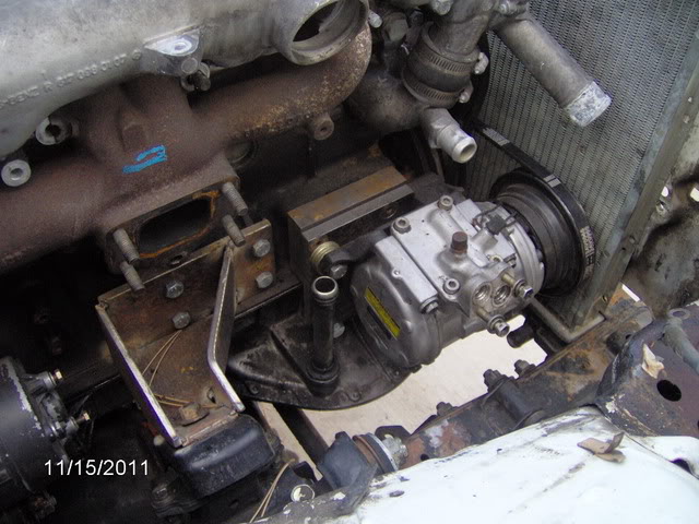
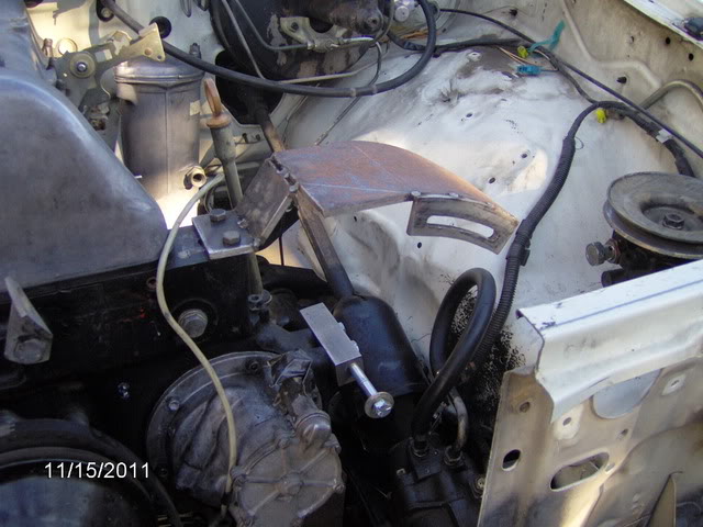
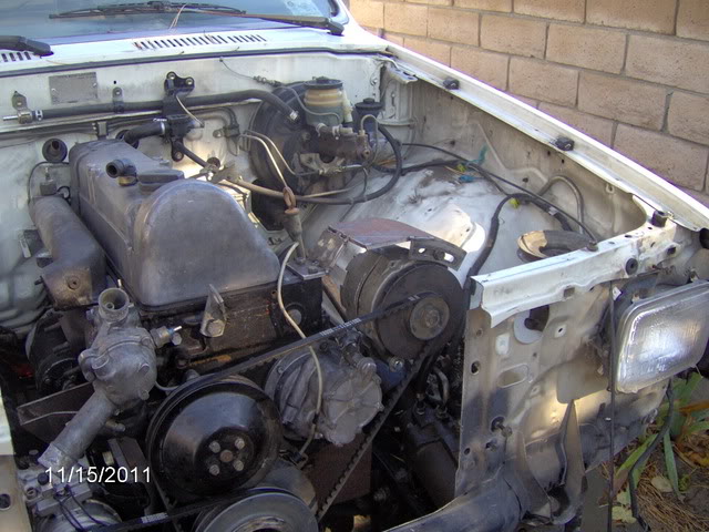
RBX, Here are a couple shots of what I have so far it's still in the design stages, so thing my change a little. As for my P/S pump I will be using a TC style from a late 90's or early 200? GM, have to see what I can find at P&P, this way I will be all set up for ram assist when I do my SAS.
A/C mounting
GM alternator mounting in progress, again only tacked
With alternator and belt
A/C mounting
GM alternator mounting in progress, again only tacked
With alternator and belt


