Oregon's Lone Wolf 3.4 swap
 03-19-2015, 09:16 PM
#121
Registered User
Thread Starter
I'll be waiting to see how it goes on Sat.!!  Good on you, for taking this project on!! Just remember, be patient, take one step at a time, and you'll get there!
A yr ago I bought my oldest son a $350 car-- to get to work and to teacher him how to maintain a car. I've pulled all the parts he's needed out of the pick n' pull, as it's a waste, buying new parts for a $350 car!! All of the work required I've assisted him, but ensured he's done the lions' share of the work, except for the last electrical problem. He's come a long way.
I'm not sure if it's a great idea to sub an Auto ECU as suggested earlier, more re-pinning would be required!

Good on you, for taking this project on!! Just remember, be patient, take one step at a time, and you'll get there!A yr ago I bought my oldest son a $350 car-- to get to work and to teacher him how to maintain a car. I've pulled all the parts he's needed out of the pick n' pull, as it's a waste, buying new parts for a $350 car!! All of the work required I've assisted him, but ensured he's done the lions' share of the work, except for the last electrical problem. He's come a long way.
I'm not sure if it's a great idea to sub an Auto ECU as suggested earlier, more re-pinning would be required!
Yeah, I didn't think going with an auto ECU would have been something I would do. I fought like hell getting all those plugs wired anyway, and to do it over again.......no thanks for me.
I'll know more on Mon. as I'm headed out of town. I have eliminated everything I can think of that is keeping this rig from starting. At least when I turned the key the first time it didn't blow up!!

 03-19-2015, 09:33 PM
#122
Registered User
Thread Starter
Well, I spend a couple hours getting most everything put back together. I tore into the valve covers to check the cam timing at Compression TDC. I did it right the first time.................just like the clutch. Figured I would hold off on the radiator fluid just in case. Yeah, just another engine to most of you...........but to me it is freaking WOW. 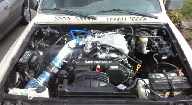
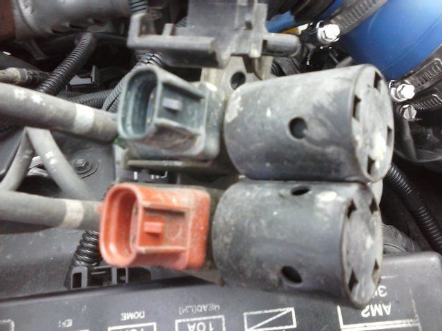
I have a question about the vacuum hoses that hook up to the transfer case in front. The hoses are marked with a light blue and white mark. Here is the part that it went to on the 3.0. Just where do these vacuum lines go? Just to any vacuum line? Can they be jointed together on a t with one line going to vacuum port?
Since I am running manual hubs do I need these as I think they go for an actuator switch of for the 4x4. ??

The other question is I am having a hard time figuring out how the engine harness runs on the drivers side. I see where it clips in, and the other part that screws to the engine mount location, but the curve would be facing front when I would think that it goes back to hook up with the 02 sensors. And, anybody know with a MT which plugs I can cut off that would be going to the auto transmission? This is an Auto Harness.
Thanks guys...........I'll get back to it on Monday.....going out for some fun doing this


 without

I have a question about the vacuum hoses that hook up to the transfer case in front. The hoses are marked with a light blue and white mark. Here is the part that it went to on the 3.0. Just where do these vacuum lines go? Just to any vacuum line? Can they be jointed together on a t with one line going to vacuum port?
Since I am running manual hubs do I need these as I think they go for an actuator switch of for the 4x4. ??

The other question is I am having a hard time figuring out how the engine harness runs on the drivers side. I see where it clips in, and the other part that screws to the engine mount location, but the curve would be facing front when I would think that it goes back to hook up with the 02 sensors. And, anybody know with a MT which plugs I can cut off that would be going to the auto transmission? This is an Auto Harness.
Thanks guys...........I'll get back to it on Monday.....going out for some fun doing this
without
Last edited by Oregon'sLoneWolf; 03-19-2015 at 09:46 PM.
03-20-2015, 09:08 AM
#123
Registered User
I have a question about the vacuum hoses that hook up to the transfer case in front. The hoses are marked with a light blue and white mark. Here is the part that it went to on the 3.0. Just where do these vacuum lines go? Just to any vacuum line? Can they be jointed together on a t with one line going to vacuum port?
Since I am running manual hubs do I need these as I think they go for an actuator switch of for the 4x4. ??
Since I am running manual hubs do I need these as I think they go for an actuator switch of for the 4x4. ??
The other question is I am having a hard time figuring out how the engine harness runs on the drivers side. I see where it clips in, and the other part that screws to the engine mount location, but the curve would be facing front when I would think that it goes back to hook up with the 02 sensors. And, anybody know with a MT which plugs I can cut off that would be going to the auto transmission? This is an Auto Harness.
The rest of the 3.4 A/T wires are unused with a M/T and you can do whatever with them, I disassembled my 3.4 A/T harness to remove them all together (which I DO NOT recommend, total pain) or you can just leave them cutoff and wrap with electrical tape.
03-24-2015, 02:14 PM
#124
Registered User
Thread Starter
Those vacuum hoses normally go to the ADD actuator on the front differential (the transfer case is bolted to the back of the transmission) and are responsible for engaging and disengaging the sleeve to connect the driver side axle to the differential. If you still have the original ADD diff you will need to do something to keep your 4x4 working: swap in a non-ADD diff (or just replace the ADD tube with a non-ADD tube without the actuator attached), do something to "lock" the sleeve in the engaged position in the actuator, or wire up those VSVs to engage when the transfer case is shifted to 4Hi/4Lo and disengage when shifted to 2Hi. I chose to modify the wiring to keep the ADD fully functional (even though I have had manual hubs for close to 10 years and a non-ADD diff in the shed); all the wiring is documented at the end of my swap thread.
All (or just about all) of the plugs that are on the 3.4 A/T harness will need to be cut off, as they won't plug into your 3.0 M/T and transfer case. You'll need identify the wires needed for reverse (so your backup lights turn on when shifted to reverse), as well as any 4x4 wires from the transfer case; basically you're looking for all the wires that plug into your 3.0's M/T and transfer case. Then, go and cut those connectors (with at least 6" of wire) off your 3.0 engine harness and solder them to the appropriate wires on the 3.4 A/T harness you're using, and plug them into your 3.0 M/T and transfer case.
The rest of the 3.4 A/T wires are unused with a M/T and you can do whatever with them, I disassembled my 3.4 A/T harness to remove them all together (which I DO NOT recommend, total pain) or you can just leave them cutoff and wrap with electrical tape.
Last edited by Oregon'sLoneWolf; 03-24-2015 at 04:19 PM.
03-24-2015, 02:19 PM
#125
Registered User
Thread Starter
New computer came and still only get .703 volts at the IGN wire. Both BATT and B+ have 12 volts.......Two computers can't be bad! I am at a complete loss with exception of the possibility that the one IGN wire is just not getting a good enough connection. Must be a wiring problem with that damn E5 plug after all.
I don't want to admit failure just yet. Perhaps the E5 plug just got damaged somehow during the wiring process of that plug. I just don't know. (
(
Edit.............It turned out that was the problem all along. I ignored it an over thought the entire thing............but learned a lot!!)
I don't want to admit failure just yet. Perhaps the E5 plug just got damaged somehow during the wiring process of that plug. I just don't know.
(Edit.............It turned out that was the problem all along. I ignored it an over thought the entire thing............but learned a lot!!)
Last edited by Oregon'sLoneWolf; 04-12-2015 at 02:06 PM.
03-25-2015, 05:47 AM
#126
I was affraid that wouldn't make a difference. What is the "ign" wire?
edit: From previous posts I think you mean IGF wire which is supposed to be 4.5-5.5 volts. You have a wiring problem on your hands. You need to make a cheat sheet of what you've pinned. You're going to have to comb through your wiring anyway. This will be a good way to double/triple/quadruple check your wiring and be able to give us something we can help you with. Are all the parts from the same doner, or have you mismatched?
edit: From previous posts I think you mean IGF wire which is supposed to be 4.5-5.5 volts. You have a wiring problem on your hands. You need to make a cheat sheet of what you've pinned. You're going to have to comb through your wiring anyway. This will be a good way to double/triple/quadruple check your wiring and be able to give us something we can help you with. Are all the parts from the same doner, or have you mismatched?
Last edited by vasinvictor; 03-25-2015 at 05:59 AM.
03-25-2015, 11:53 AM
#127
Registered User
Thread Starter
I was affraid that wouldn't make a difference. What is the "ign" wire?
edit: From previous posts I think you mean IGF wire which is supposed to be 4.5-5.5 volts. You have a wiring problem on your hands. You need to make a cheat sheet of what you've pinned. You're going to have to comb through your wiring anyway. This will be a good way to double/triple/quadruple check your wiring and be able to give us something we can help you with. Are all the parts from the same doner, or have you mismatched?
edit: From previous posts I think you mean IGF wire which is supposed to be 4.5-5.5 volts. You have a wiring problem on your hands. You need to make a cheat sheet of what you've pinned. You're going to have to comb through your wiring anyway. This will be a good way to double/triple/quadruple check your wiring and be able to give us something we can help you with. Are all the parts from the same doner, or have you mismatched?
As far as from the same donor, unfortunately no. But, it is a 97 Auto harness and 97 MT ECU, so therefore yes, mismatched in a way. I had spoken to a few people with the same year and with the auto harness and they suggested I try the cheat sheet on the 3.4 swap 101 that they had success with. I had no wire color confusion. https://www.yotatech.com/forums/f160...-101-a-239002/
I do have a note in my records about a possible loose connection to a ground wire with an E03 function. It appears according to the EWD that this is a ground to the ECU. I pulled that wire and noticed it had a bad connecter pin so i soldered a new one on, still only .703 at pin 17 on both computers.
I'm going to check the FSM as maybe, just maybe it could be something else, maybe in the fuse box with the EFI or something.? Not sure if that would be it as my B+ is getting 12 volts. hmmm
Last edited by Oregon'sLoneWolf; 03-25-2015 at 04:18 PM.
03-25-2015, 03:13 PM
#128
Registered User

Join Date: Dec 2014
Posts: 59
Likes: 0
Received 0 Likes
on
0 Posts
So first off I must admit I didnt read your whole thread because wow thats a lot of posting and I have been working on my swap. However I caught your section on the maf and thought I would give my 2 cents.
The engine will not (from my experience) start without the maf. If you are having continuous cranking or it starts and dies check your maf wiring. Does your harness match your ECM? I see they are the same year but same car as well? The reason I ask is different models used different mafs and blah blah blah.. I found my issue was my harness needed the older style maf. If you compare the mafs on TIS you will see that plugs 4 and 5 are switched. Also make sure you have power in BOTH places indicated on TIS at your maf. I was missing one. Took me 3 days to find it.
As for all your other wiring stuff be patient use a multimeter to verify things. Be sure you are looking at the right EWDs for the harness and ECM RESPECTIVELY... toyota changed wires around on different models /years etc on the 3.4.
Feel free to pm me if you need help (im one step ahead of you on my swap and am happy to help if I can)
Good Luck!
03-25-2015, 07:03 PM
#130
Registered User
Thread Starter
Thanks man, I really appreciate the offer. I'm in your sister city in OR. You wouldn't happen to have a working MT ECU for a Runner sitting around would you? The odds of two being bad are pretty out there and all of my tests point right back to the ECU. Other than that, I have everything......thanks again.
03-25-2015, 07:13 PM
#131
Registered User
Thread Starter
So first off I must admit I didnt read your whole thread because wow thats a lot of posting and I have been working on my swap. However I caught your section on the maf and thought I would give my 2 cents.
The engine will not (from my experience) start without the maf. If you are having continuous cranking or it starts and dies check your maf wiring. Does your harness match your ECM? I see they are the same year but same car as well? The reason I ask is different models used different mafs and blah blah blah.. I found my issue was my harness needed the older style maf. If you compare the mafs on TIS you will see that plugs 4 and 5 are switched. Also make sure you have power in BOTH places indicated on TIS at your maf. I was missing one. Took me 3 days to find it.
As for all your other wiring stuff be patient use a multimeter to verify things. Be sure you are looking at the right EWDs for the harness and ECM RESPECTIVELY... toyota changed wires around on different models /years etc on the 3.4.
Feel free to pm me if you need help (im one step ahead of you on my swap and am happy to help if I can)
Good Luck!
The engine will not (from my experience) start without the maf. If you are having continuous cranking or it starts and dies check your maf wiring. Does your harness match your ECM? I see they are the same year but same car as well? The reason I ask is different models used different mafs and blah blah blah.. I found my issue was my harness needed the older style maf. If you compare the mafs on TIS you will see that plugs 4 and 5 are switched. Also make sure you have power in BOTH places indicated on TIS at your maf. I was missing one. Took me 3 days to find it.
As for all your other wiring stuff be patient use a multimeter to verify things. Be sure you are looking at the right EWDs for the harness and ECM RESPECTIVELY... toyota changed wires around on different models /years etc on the 3.4.
Feel free to pm me if you need help (im one step ahead of you on my swap and am happy to help if I can)
Good Luck!
Good to know it is needed as from what mechanics say, that isn't needed for it to start. Must be just the Toyota.
Last edited by Oregon'sLoneWolf; 03-25-2015 at 07:49 PM.
03-26-2015, 06:05 AM
#132
Man it's not gonna be two bad ECUs. It's unlikely to be even one bad ECU. Toyota ECUs are just damn rock solid.
Do you have 12v at the B+ B-R wire on your Ignitor? Use the BR wire on the ignitor for your ground. You should have 12v when the key is in IG2 (not cranking) Just making sure, but you have you "ground pack" hooked up on the driver side of the intake manifold? It's below the Dignostic pin box. All the ignitor, and ECU grounds there.
Can you send me your 97 EWD so I can give you proper plugs pins and color?
03-26-2015, 11:28 AM
#133
Registered User
Thread Starter
Man it's not gonna be two bad ECUs. It's unlikely to be even one bad ECU. Toyota ECUs are just damn rock solid.
Do you have 12v at the B+ B-R wire on your Ignitor? Use the BR wire on the ignitor for your ground. You should have 12v when the key is in IG2 (not cranking) Just making sure, but you have you "ground pack" hooked up on the driver side of the intake manifold? It's below the Dignostic pin box. All the ignitor, and ECU grounds there.
Can you send me your 97 EWD so I can give you proper plugs pins and color?
Do you have 12v at the B+ B-R wire on your Ignitor? Use the BR wire on the ignitor for your ground. You should have 12v when the key is in IG2 (not cranking) Just making sure, but you have you "ground pack" hooked up on the driver side of the intake manifold? It's below the Dignostic pin box. All the ignitor, and ECU grounds there.
Can you send me your 97 EWD so I can give you proper plugs pins and color?
But wait, the diagnotic pin box has a purple and white wire that was tucked to where I didn't notice Looks like it goes to the pin 7 of the E6 plug just sitting there unattached. Probably not sending back a timing signal if I understand it correctly.
Last edited by Oregon'sLoneWolf; 03-26-2015 at 01:06 PM.
03-26-2015, 01:25 PM
#134
I left my V-W wire going to the diagnostic unhooked, I just use the OBD 2 for diagnostics. But my truck still starts fine. All the wire does is send data to from the ecu to a code reader.
03-26-2015, 05:57 PM
#135
Registered User
Thread Starter
Well cool, now I can test my timing etc I guess. I am wired for ODBII as well though. I didn't think this would keep it from starting.
03-28-2015, 02:42 PM
#136
Registered User
Thread Starter
Finally I found the problem. A ground pin connector had just a slight break in the edge of the pin. Yup, I must have damaged it getting the pins out. Heck, I have been saying all along it was a problem with that damn E5 plug.
Starts stumbles then dies. Checked the coils two aren't getting spark still. The igniter isn't throwing a code. Continuity checked all wire out from ECU to igniter, igniter to coils. Conclusion..........my E5 plug is damaged.
Starts stumbles then dies. Checked the coils two aren't getting spark still. The igniter isn't throwing a code. Continuity checked all wire out from ECU to igniter, igniter to coils. Conclusion..........my E5 plug is damaged.
Last edited by Oregon'sLoneWolf; 04-12-2015 at 02:01 PM.
04-10-2015, 04:15 PM
#137
Registered User
Thread Starter
Engine runs
SHHHHH............can you hear it? IT RUNS!! I finally decided that the E5 plug I had mentioned might have been the problem all along was the cause of the IGT3 to not get the signal........replaced the plug. Gets spark.
Thanks to Cr@ves4wheelin for pointing out the obvious to me as the reason why it was not remaining started was due to a vacuum leak. My vacuum line which would have gone to the EGR, which it doesn't have, was not plugged.
Here is the first start up when it actually ran. [YOUTUBE][/YOUTUBE] https://www.youtube.com/watch?v=2Byj...ature=youtu.be
My thermostat was installed upside down with the hole facing down and my heater hoses were switched. It should be drivers side engine to left heater hose out on the firewall and Pass side engine to heater intake. One previous post was wrong. Only throws one code for the 02 sensors but duh, my exhaust isn't hooked up. Thanks to those that helped me along the way.
Still some minor bugs, but nothing I can't figure out..........I think.

https://www.youtube.com/watch?v=2Byj...ature=youtu.be
Thanks to Cr@ves4wheelin for pointing out the obvious to me as the reason why it was not remaining started was due to a vacuum leak. My vacuum line which would have gone to the EGR, which it doesn't have, was not plugged.
Here is the first start up when it actually ran. [YOUTUBE][/YOUTUBE] https://www.youtube.com/watch?v=2Byj...ature=youtu.be
My thermostat was installed upside down with the hole facing down and my heater hoses were switched. It should be drivers side engine to left heater hose out on the firewall and Pass side engine to heater intake. One previous post was wrong. Only throws one code for the 02 sensors but duh, my exhaust isn't hooked up. Thanks to those that helped me along the way.
Still some minor bugs, but nothing I can't figure out..........I think.
https://www.youtube.com/watch?v=2Byj...ature=youtu.be
Last edited by Oregon'sLoneWolf; 04-12-2015 at 02:00 PM.

 04-12-2015, 04:10 PM
#140
Hey bud, good to hear. Saw your video, sounds great. Don't forget there's a vacuum hook up under the black foam thing on the side of the intake, right next to the throttle body. It's for your PCV valve.


