When you click on links to various merchants on this site and make a purchase, this can result in this site earning a commission. Affiliate programs and affiliations include, but are not limited to, the eBay Partner Network.
YEAH!!!!!!!!!!!!!!!! Finally got this post repaired and the pictures put back...........after a couple years.
Hopefully its still helping people.
12-22-2017
--------------------------------------------------------------------------------------------
It seems a lot of the same questions come up repeatedly so I though that I would make a post that covers many of the issues that seems to stump people. This is in no way meant to be a "how to swap a 3.4" or an instruction manual. This is just my thoughts and ideas on how I did things. I am not an expert and do not have anything to do with cars in my professional life. I teach elementary school. My only knowledge is doing the swap only twice and that hardly qualifies me as an expert and I not pretending to be. There are things that I still do not understand, like the A/C system . Hopefully someone can add a good , detailed writeup on that someday on HOW it works and some good diagrams and pictures.
If I made mistakes, please point them out for everyone's benefit who reads this. I don't want to spread misinformation. If you want to be the smartest kid in class and tell me how stupid my thoughts are, save it.
Also, I noticed that the videos do not show up on my iPad. Sorry.
Mounting the Airbox:
This is surely not the most difficult task of the swap but I thought that I would include it nonetheless. You can do this without the factory snorkel behind the fender or not. Either way, the motor is going to get enough air. I have done both. If you want a look at how to mount it with the snorkel you can take a look at my thread. The link is in my signature, or check out Cadman's thread for a REALLY sweet job. I still believe that Cadman has the best 3.4 swap thread of the billions of pages on the internet, although it doesn't cover any wiring info.
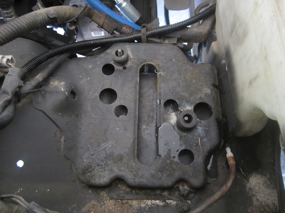
Obviously to mount the box you have to remove the battery and hopefully the tray is not corroded to nothing like mine was from years of acid leaking on it apparently. The one I am working on now is in good shape. To start, I welded a couple of bolts from underneath to serve as studs to accept the airbox and keep it secure. If you do not have a welder, you could leave the bolts in there loose and cinch them up when you tighten the box down. You can see on the one in the bottom of the picture I had to cut a slit in the metal to allow the bolt to slide in and to the hole and then weld it back up.
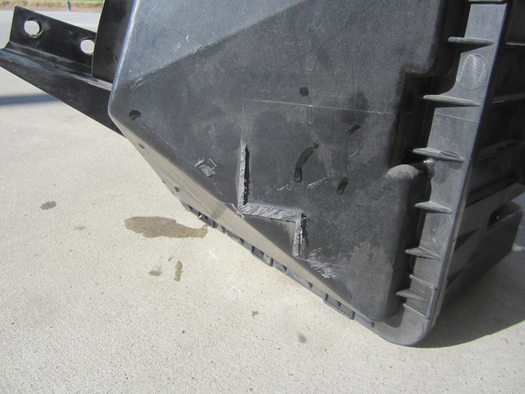
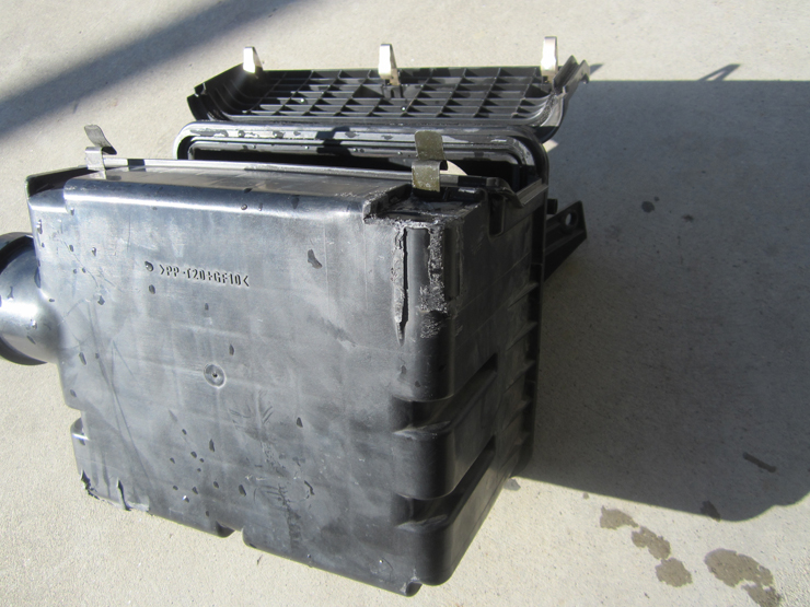
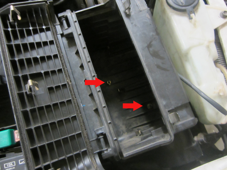
Then the box itself has to be modified a bit. The stock tabs will be cut off. You can use the front, lower tab as a mount if you want (I did on mine) but the other two I have cut off on both swaps that I have done. Be careful not to cut/grind through the box obviously. You can see here that the tabs have been removed by my trusty Harbor Freight body saw. Best $18 ever!! You will notice in the last picture that I also drilled two hole to receive the studs that I welded on earlier.
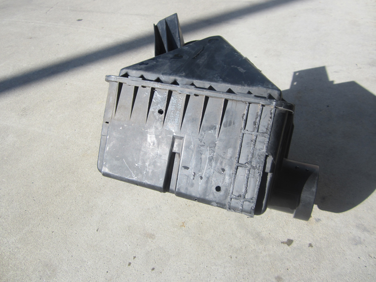
The box should flex a little so I remove the stock rubber grommets from the 3.4 airbox and put them on the studs before dropping the box on to provide for a little cushion and for it to flex a little.
Attach some nuts to the studs and the box will be secure. Tighten them up, but not too tight.
Mounting the EVAP Box:
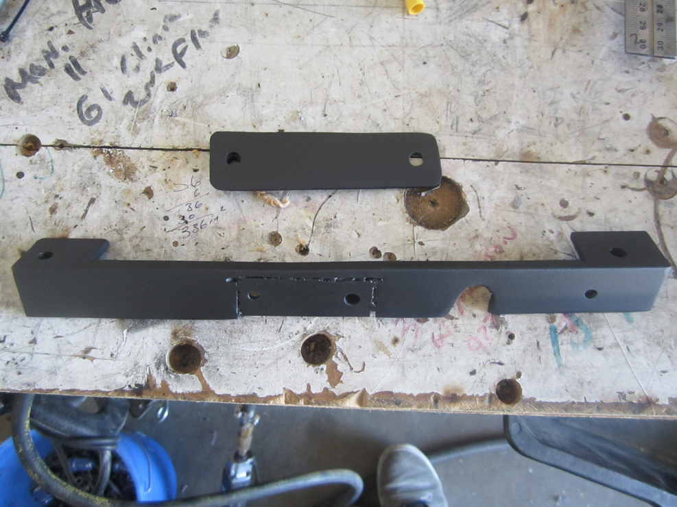
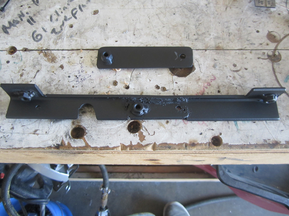
This is nothing really special and I am nothing of a metal fabricator. This was made from a piece of angle iron that I had laying around probably from an old bed frame that someone was tossing and I grabbed one day. You can buy small pieces of angle iron at Lowes or Home Depot for a few bucks. I first cut the piece wrong and had to reweld it back in cause I didn't have anymore and didn't feel like making a run to the store so that's why there is a patch in these pictures. The piece will have to be cut out to fit around the bolts and holds the rubber bumper for the hood. Once you get that relief notched out just mark your piece and drill the holes for the flanges on the box the bolt into. Again, I welded nuts on the back but if you do not have a welder, you could just use nuts and bolts just as well. The only semi-tricky thing is that the ears on the top of the box to mount it at set at different angles to accommodate the Tacoma, or Runner's, inner fender. This means that you will have to bend each tab to match that angle. I just mounted the bracket and slipped a crescent wrench over the tabs and bent them a little until the box mated to it well. The bottom has to be supported or the ears on the box will break eventually. A simple bracket is used to support it. There is already a threaded hole in the inner fender to make it easy.
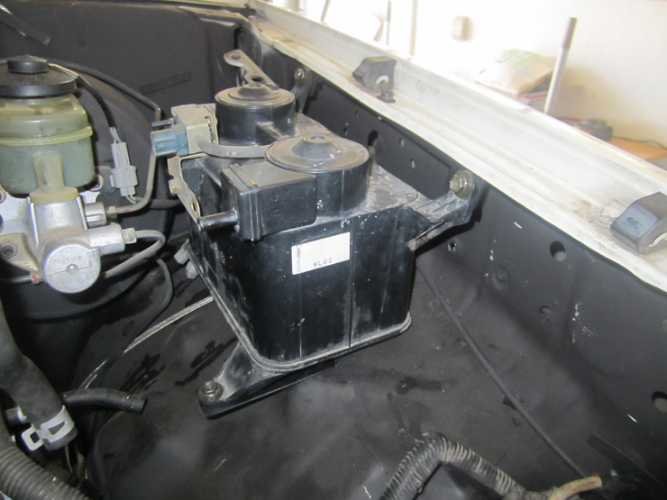
Installed and hooked up.
The Battery Harness:
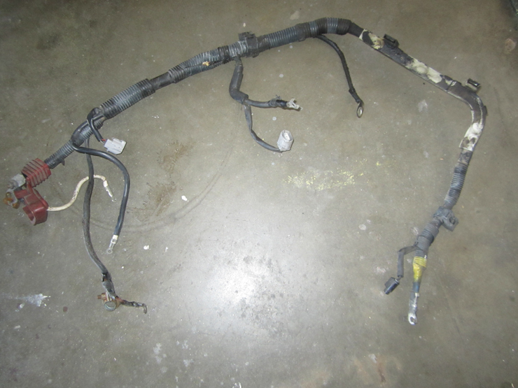
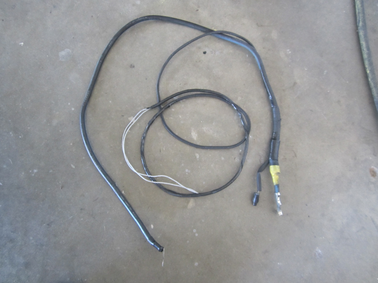
The battery harness runs from the starter around the oil pan and up to the battery. In its stock form, we do not need everything contained in there so disassemble it to simplify it.
This is what it looks like stock.
There isn't much that is going to get your hands more filthy that this harness and the process of taking it apart. There are years of old oil, road grime, and now taking apart wires covered in old black tape. I would suggest just slicing through the split loom with a razor knife and splitting it open like a fish and pulling everything out. Do not throw anything away but, all you really need is the large battery cable to the starter and the smaller starter trigger wire.
The large cable is what feeds the battery the power to crank the motor and the trigger wire engages the solenoid (kind of a large relay which I will get into later). The 3.4 harness has no starter wire in it so one has to be ran for the vehicle to start. It will run with the 3.4 harness into the cab so that it is protected in the same loom and ends in the passenger kick panel where it is needed.
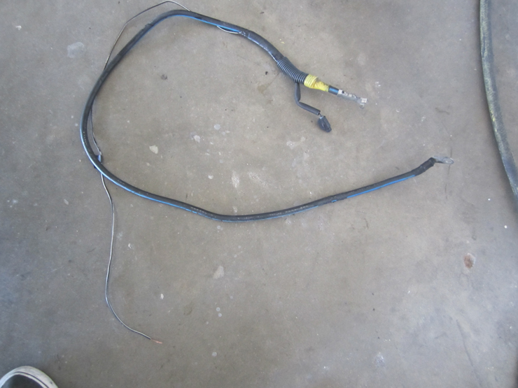
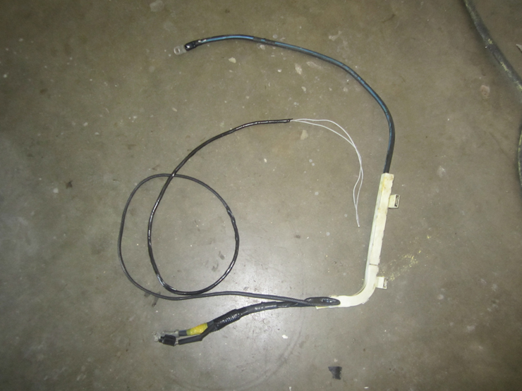
When everything else is stripped out of the battery harness, this is what is needed. Just the cable and the trigger wire.
The ground cable can be reused but an upgrade isn't a bad thing. The alternator plug will also be reused if you are running the 3.4 alternator and spliced onto the 3.0 alternator wiring. To wire the 3.4 alternator to the 3.0 harness in the vehicle, just match the three wire colors together and that is it.
The 3.4 motor harness does not have a provision for the starter wire. So for the starter to operate correctly when the key is turned, one needs to be ran into the cab from the starter. This should be setup now while you are working on the battery harness. To run the wire into the cab, it first needs to be extended about 4-5ft. 14ga. wire is enough, but you could also double up a smaller gauge wire if that is all you have, or if you are scavenging wire for your swap donor. If you are doubling up smaller wire, a trick is to put one end of each length in a vise or secured similarly, put the other ends both in your drill and start the drill to twist the wires together for a cleaner install. Tape everything up after that to protect the wire and keep the factory look.
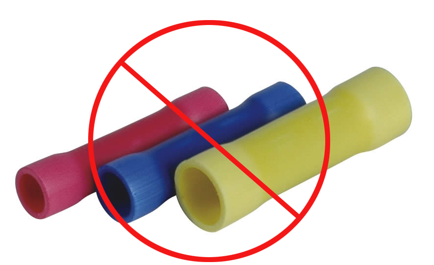
To extend the wire, it should be soldered and in fact, every connection made should be soldered!! Butt connectors are not a friend when it comes to computer controlled systems. You may have them work at first, but their failure rate is MUCH higher from corrosion, bad crimps, etc. Remember that many of the sensors run on resistance and poor connections greatly impact the resistance of a wire. If you are installing a stereo in your car, butt connectors are fine. For computer controlled systems, they are a terrible choice.
I'll go over how to CORRECTLY solder wires together.
First, you are going to need a decent soldering gun or pencil. Anything will work, but I prefer my Weller pencil tip. This will get any of the wires involved in the swap hot enough to solder correctly. Anything smaller and you may have a difficult time achieving sufficient penetration to ensure a solid connection. Another tip is that the tip will get a coating of oxide on it over time. Have a damp sponge handy and rub the tip on it after each use. the will endure a hot surface each time you need to apply heat. Alternatively, I often use a small wire wheel on my cordless drill and give the tip a few second with the wheel when it is not heating the wire effectively due to oxide buildup.
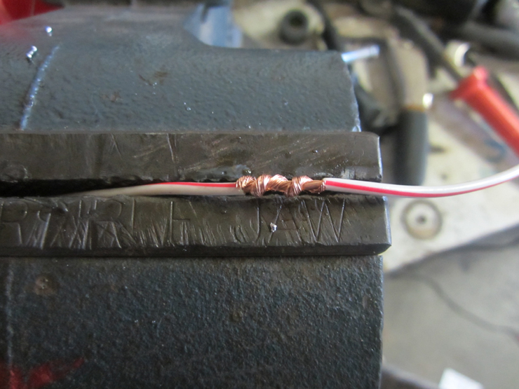
First, you want to strip about 1/4"-1/2" of the insulation back and join the wires together. If you are extending a wire, they should mate parallel to each like this.
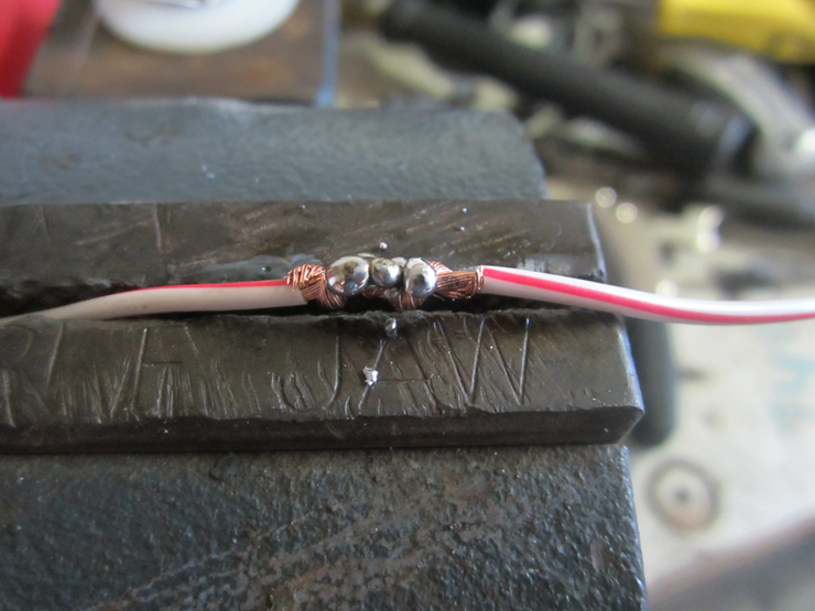
Soldering is much like welding in that you have to have the solder penetrate the wire to make a good joint. This requires heat and a good flow to the wire. It is important to realize that anytime you solder something, you do NOT use the soldering iron to melt the solder; you use the gun to heat the wire to a point where the WIRE can melt the solder. This will allow the solder to flow through the stands of the wire and make a solid connection. Many people will put the tip on the wire and start applying the solder where the tip is meeting the wire. This will usually result in poor connections that will fail in time. This is what poor penetration looks like.
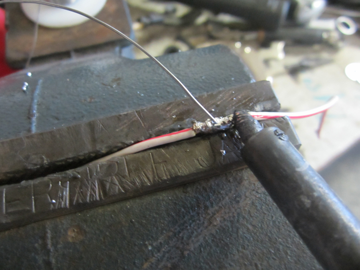
Again, the proper way is to heat the wire and allow that to be hot enough to melt the solder. To do this, the tip should be about 1/4" away from where you are applying the solder to the wire when using a pencil type gun.
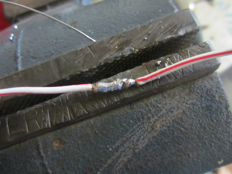
Apply the solder slowly, allowing it to melt and start to flow throughout the strands. A good joint will show good penetration on EVERY side. Not just the side you were working on like the picture that is two above this. Here is a well soldered joint ready to install that will last longer than the truck will. It will look like this on any side as I rotate it. Don't forget to add some heat shrink tubing over the joint.
Going back to the starter harness, the only wires that are needed to make the vehicle start are the large battery cable that will run over to the battery, and the trigger wire that will eventually pass through the firewall with the 3.4 main harness. This is a shot all taped up and ready in go. Much simpler.
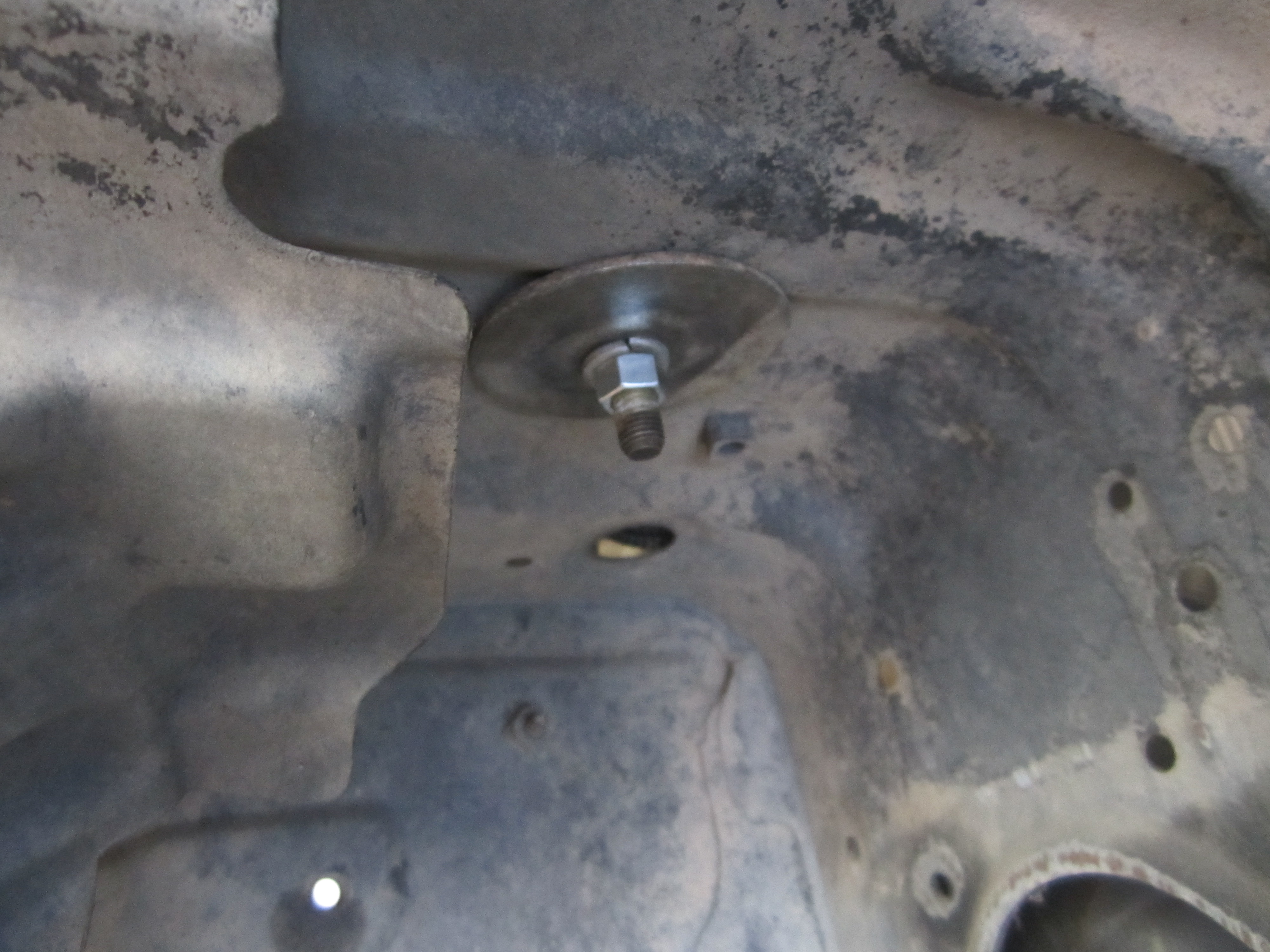
Measure out and add the guide that clips to the bottom of the motor and serves to protect the main battery cable. This is done and ready to install. I'll cover how to wire the starter down further.
Battery Relocation and Wiring:
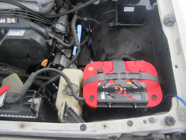
The battery will have to be moved to the driver's side to allow the airbox to be mounted. Again, there a many ways to do this. You could use a battery box that is mounted securely, or use something as simple as a tie strap or bungee cord. I recommend the box and mounting it securely. Do it right.
There are a variety of companies that sell premade boxes and some that are designed for specific batteries such as an Optima. Ballistic Fab and Trail Gear both make one. I have the Ballistic and just installed the Trail Gear one in another swap. the Ballistic is a much better piece. It was heavier, had more mounting options and fit the battery better. Both used Optima 34/78 batteries. Regardless, the principals are the same. Make the battery secure! A battery is a LOT of weight to be anything less.
The inner fender shelf that it will locate too is fairly level as is but does have a slight slope towards the motor. Just enough to make things look "off" without some shimming on the motor side. A simple washer under the middle bolt in the picture was enough to achieve the battery sitting at level. The Optima has recesses in the bottom of it so the bolts have to be placed so the battery is not sitting on the bolts and instead, the bolts are in the recesses on the bottom of the battery. Just takes a few minutes or lining things up and making some marks.
Here is the battery with the bolts ran through the inner fender well.
Putting nuts on the bolts in the fender well would mean over time the metal of the fender would eventually rip or tear with stress. To distribute the weight, and keep this from happening, a large washer, or piece of metal should be used. This will keep everything solid. The other one is under the plastic in this picture but both bolts received large washers.
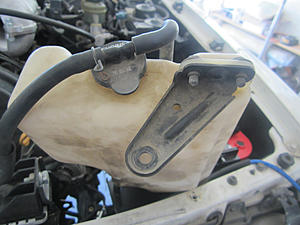
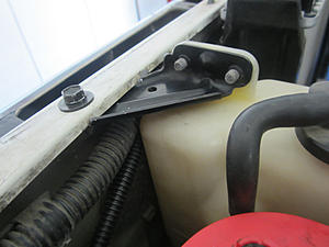
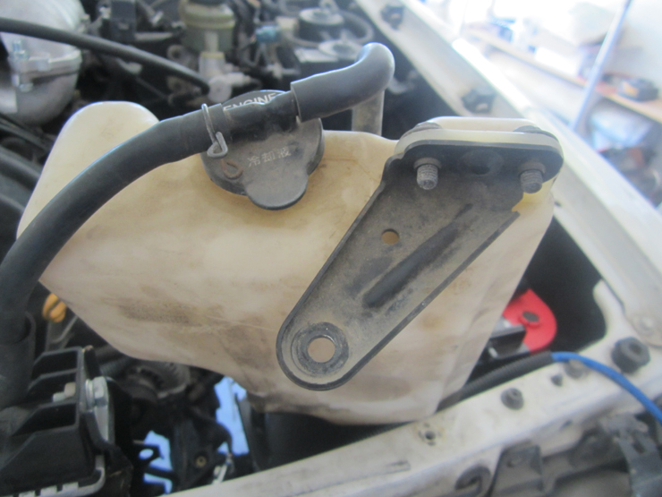
Now that the battery is in and solid, the coolant overflow will not fit. That will also have to be modified and everything will fit like it was designed that way. First, you need to remove the bracket and reinstall it on the other side.
Place the tank and bracket in the opening between the radiator and the battery and mark a spot to drill a hole in the core support. I welded a nut on the bottom of the bracket but again, you could use a bolt by hand. The lip on the edges of the bracket will not allow the bottle to sit flush so use some washers between the top of the bracket and the bottom of the core support as a shim or spacer to make sure you can tighten it enough and the bottom doesn't want to start to tilt.
I also used my body saw to slice a groove in the metal to sit in the lip on the bottom of the core support. This keeps the tank from wanting to swivel from side to side since there is only one bolt holding it in. You can barely see it in the picture.
Completed and ready to move on to the wiring.
Wiring in the fuse panel, or even opening the fuse panel, is something that I know makes people nervous like anything electrical. However, this step is quite simple and nothing that the average person cannot do. If you can change your fuel pump, you can do this.
First though, the reason why we have run a new wire to the fuse panel is that the fuse panel is no longer 12" from the battery like it was. That wire has to be extended to reach the new battery location and soldering an extension on is not a good option for a wire that large. It is always better to have a wire intact and in one piece, especially the wire that feeds the electrical system of most of the vehicle. Size here is up to you, some subscribe to the bigger is better theory and there is merit in that. Supplying a wire that provides more than the current needed is never a BAD thing, but it does make the job harder. When I did my swap I used 4ga. to run across and connect to the fuse panel. It was a real pain the ass to make it fit in the fuse panel and the connectors are so large that the bottom would barely reattach. On the current swap I am working on, I decided to use 8ga. wire from an off-the-shelf amp kit bought at any stereo shop. Buying an amp kit is also a good option because it comes with the terminals you need and some ground wire for upgrading your grounds from the firewall to the motor(which you should most definitely do). Unless you could use a spare, pick one up without the RCA cable to save a few bucks.
8ga. wire over a 6-7' run will supply about 150amps. That is PLENTY of current to supply everything in the fuse panel at the same time so nothing larger is needed.
Let wire it up. First, remove the two bolts that hold the fuse panel to the body and flip it upside down. You will see the access door on the that opens by releasing the two tabs and then pulling it out of the hinges. That will go back on so don't lose it. Next, unlock the main 80A fuse by pressing the release tab with a small screwdriver or pick.
Then gently push it out the bottom and you will have access to the wires that need to be changed. This is an "after the wire had been swapped" picture. I forgot the before. Essentially, the large white wire that went to the battery terminal will be removed and replaced by the wire that you are running from your amp kit or wherever you got your wire.
Route it through the box and out the hole in the front. Nice Toyota left future swappers a place to upgrade the box.
Slide the 80amp fuse back in until it is locked back into position, reinstall the bottom cover and bolt the panel back onto the body and you are done.
The new battery wire will run under the core support and over to the battery. There is already a wiring loom under there so following that with zip ties is a good option. Most of the time a fuse or breaker is not needed at the battery side of the wire but an extra security measure would be to add one in the result of a short of the new wire from a front end collision, or something similar. A 100amp fuse or breaker should be enough to protect the wire and still allow full power to the fuse panel without overloading the wire and popping the fuse.
Routing The Harness Into The Cab:
The newer generation vehicles that these 3.4 motors are from route the harness into the cab much closer to the center of the firewall than the older ones and the ECM is high inside the dashboard rather than in the kick panel. This makes the harness JUST long enough to reach the kick panel but it does reach without many inches to spare. However, the rubber boot that protect the harness in the motor compartment is not long enough to reach across the firewall to the opening where the 3.0 harness went through, so it has to be modified. After working with it, the boot will protect the harness all the way across the motor compartment and into the cab. This not only protects it but makes it appear factory. YOU WILL NEED THE GROMMET FROM THE 3.0 HARNESS so do not toss that harness just yet (you will also need the speed sensor plug from it as well).
To get started, remove the gray tape from the outside of the boot. This will reveal another layer of tape underneath.
The rubber is actually two pieces that are taped together so we want to separate those. Remove the bottom layer of gray tape as well until there is no tape attached to the rubber.
The boots can now be moved independently and stretched as we need to make a clean, factory look and watertight seal. To pass through the 3.0 grommet, the metal flange and the end of the boot will need to be cut off with a razor knife. Cut as close as possible to the edge to leave as much of the boot intact as possible.
Before we start to reassemble the boots and join them, now is time to run the starter wire into the cab. This is the most logical place to do it as it will be protected, look clean and also enter the cab and be located with the plugs in the kick panel where it will be needed to wire into the 3.0 harness.
Simply run the wire towards the firewall side between where the boots are split and through the outside of the harness where the metal flange was cut off.
Now with the starter wire inside the harness, it can be reassembled to keep it watertight. The motor side boot will stretch quite a bit. Pull that over while stretching the other side as well. WD-40 through a straw is your friend here, especially on the firewall side. Secure them together with a zip tie.
The joint should be sealed as the zip ties are not enough. They are simply "clamps". 3M Mastic tape is the best thing to use as its flexible and fuses to itself. This is a MUCH better option than black, electrical tape.
Done, sealed and ready to go through the 3.0 firewall grommet.
The 3.0 grommet may have to be opened a little with a razor knife. A little cut goes a long way here and again WD-40 is a friend keep the opening as small as possible to ensure it's as watertight as can be.
After that, it is simply a matter of pushing everything through the hole in the firewall, attaching the grommet and pulling everything as tight as you can, without pulling too tight, to get as much slack as possible in the kick panel. The factory mount for the harness can be reattached to support it and keep it from wearing by rubbing on things over the years. If you are removing the 3.0 EVAP canister, there will be threaded holes for you to use to mount the harness bracket.
All done. Clean, safe, and protected.
Repinning the Automatic Harness to a Manual Harness:
Most guys that are completing this swap, or 4x4 in general, prefer a manual transmission. However, the manual harnesses are hard to find in comparison to the auto harnesses. I assume because there were many more auto vehicles built as the 4Runner turned into a soccer mom option in the 90's. New ones can be bought for about $250 direct from Toyota. The part number for a 97 Runner manual harness is 82121-3D420. This has no EGR and is 50 states legal. The matching ECM is 89661-3d310 and can usually found at HTTP://car-part.com"] car-part.com by searching "computer box-engine" for anywhere between $50-$100.
However, with the availability of auto harnesses, it is relatively simple to convert the auto the manual. The key to being successful though is patience and homework. Other than the transmission functions, both motors need the same inputs and outputs to work and they both have EXACTLY the same sensors for like years when auto vs. manual is concerned. The problems are the plugs are different on an auto harness vs. the manual (up to 1998) and they do not interchange between the different ECM's. This is why the auto has to depinned and repinned into the manual plugs.
If you are going to use the manual ECM, you will need a set of plugs for the ECM. They are available from Toyota for about $20 for the set. This is the only cost involved is converting the harness so your saving about $230 over the cost of a new harness, and not having to disassemble the top of the motor to install it and the added cost of the new gaskets.
Manual plug part numbers for the above ECM.
A tip for ordering plugs from Toyota is that every plug starts with the part number 90980 and the last five numbers are located on the plug itself, albeit very small sometimes. For example, if you have a plug that you need to replace and the number on it is 12345, then the part number would be 90980-12345.
Again, each motor, manual and auto, have the SAME functions other than the transmission controls. Jeff Mosk's sticky in this forum provides a great resource to find each pin and what function is corresponds to. Then its just a matter of matching things up. If you have a vehicle that Jeff didn't cover, you can use the EWD's. After spending considerable time tracing out wires in the EWD's, I want to again give a thumbs up and thanks to Jeff for the awesome resouce. I can't imagine how long that took to do.
For example as to how the wires are the same function but in different location when comparing auto vs. manual, look at this EWD for a 97 Runner. It shows that the KNK2 function for an auto (a/t) is on the F(E10) plug, at terminal 16. For the manual (m/t), it is located in the B (E6) plug in terminal 3. To accomplish this, you simply take the terminal from the auto location and place it into the manual plug in the corresponding location. One done, and about 70 to go.
Taking some time up front to label the plugs really helps when you actually start to make the transfer of all the wires from the auto plugs over to the manual ones. I use a FINE tip Sharpie. This keeps me from getting confused when moving so many wires because it does become redundant, tedious and a mistake is simple to make. Also, there are TINY numbers, usually above the corner holes, to serve as reference point when labeling everything. With these new plugs, the numbers were almost impossible to see, even with a magnifying glass. I rubbed a little dirt on the plug and that helped. A little oily grime worked best as I could now see the numbers. Also, most of the EWD's have the pinouts listed somewhere on them. Just make sure you are looking at the plug from the correct side. This is where seeing the numbers on the plugs helps.
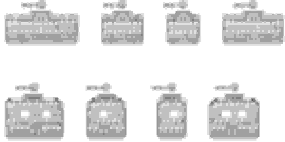
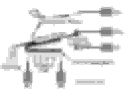
These are the different plugs. The top row is manual plugs and the bottom is auto. Always look at the plug as if it's going to plug into your eyeball. The plugs are labeled as if your eye is the receptacle for reference so again, look at them from the correct side.
A set of new manual plugs labeled and ready to go.
Auto plugs ready to be cannibalized.
Last time I did this in the cab, and there is no slack in the harness to allow for any wiggle room and made the job difficult, but doable. This time I did everything outside so I not cramping myself into the kick panel area, laying on my side, and I have plenty of room to be comfortable because I want to be focused.
Everything is here. Auto plugs labeled, manual plugs, my conversion chart, a small screwdriver to unlock the plugs, and a push pin to release the pins from the plugs.
It is very important that you DO NOT pull all the wires from the auto plugs and then try to match them up to the manual plugs. It must be done one at a time!!! There are more than one instance of the same wire colors and if you pull them all out of the auto plugs, you will not know what function a particular wire color is for and therefore, not know where it needs to go into manual plugs. You could always trace everything down with a meter, but that is a lot of unneeded time. The key is patience.
This is another great example of why taking it ONE wire at a time is important. If you look at the screen capture of the EWD for a 1997 4Runner will notice that there are two pink wires listed. One for the O2 sensor and one for the crankshaft positioning sensor. THIS IS WRONG! The actual wire for the O2 sensor is Pink with a blue stripe (P-L). If I pulled all the wires out I would have two pink wires on my diagram with only one in the harness and a pink/blue wire that I had no idea where it went because it is NOT on the diagram. Slow and steady wins the race!!!!
To get started, first you need to unlock the plugs. Pins will not come out unless the plug is unlocked. The pins will also not go in very well either if they are still locked. So ALL the plugs, donor and receiving, need to be unlocked. To do that, you need a small screwdriver to unlock the plug and something small and sharp to actually unlock the pin.
Here is a plug that is still locked. Notice the small tab is pushed in, and the plug is flat across here.
The tab needs to open so using a small screwdriver, it can be pried open with little effort.
The take a small, sharp object (I use a push pin cause it has a handle on it) and push it in to release the tab inside the plug.
When the tab is released, the wire will slide out with minimal effort. If you are having to pull on it, you are probably missing the release lever. Do not yank hard on it. That is not needed.
Follow your conversion chart and pull the first wire and then relocate it to correct hole in the manual plug that the EWD called for.
Here is a shot of my conversion chart for reference. This is not a conversion chart for every 3.4 swap out there so please don't think that you can take this and do your conversion from it. This is for the specific vehicle and ECM that I was working with. Not the one that you have.
As you can see in the first row, plug E9(E) pin 10 controls the #10 function and the wire is red. For the manual, the ECM has this function on E5(A) pin 12 and the wire is also red (all the wires are the same color when crossing over). So I will pull the red wire from E9 and move it to the E5 plug in pin 12. Easy enough and I have one completed. Double check everything and make sure its in the correct spot and then move to the next one. The is no particular order you need to go in; just as long as everything gets moved that needs to be.
You will notice that the second wire is E-12(H) pin #2 and is a V-R (violet with a red stripe)has nothing on the manual columns. This is because the manual does not need this function because it is related to the auto transmission. This wire will not be used in the manual plugs.
Here is a shot with the transfer completed. The wires coming from the manual plugs that are going to tie into the 3.0 harness for oil pressure, temp sender, tach, etc. The wires that are still in the auto plugs are all functions that are for the auto transmission and will not be used. These do not need to be taken out of the plugs and they have no purpose anymore. However, there is little room in the kick panel for all the plugs and the ECM to fit when you finish everything up and having an extra four plugs to hide away in there may prove very difficult, or maybe even impossible. I recommend removing the wires and capping them off with some heat shrink to save much-needed space later.
As with many things, the key to doing this is the homework. Making a clear, and ACCURATE conversion sheet is where most of the time will be spent doing this. I worked on mine one night UNDISTRACTED and got everything entered into Excel. Then I went over it two more times and double and then triple checked it before every touching anything on the truck. I did find a few fat finger mistakes on my initial chart I had made that would have caused me hours of grief when a CEL (Check engine light) came on. All told, I spent about 3 hours total on the chart and about an hour to move all the pins. Take your time and its a pretty easy task to save a couple hundred dollars and you are going to learn a lot about how the electronics work for the motor for future issues that you may have. Thanks and credit given to Mosk the first time I did this and the idea!!
The C.O.R. and Relays In General:
The COR(circuit opening relay) is really just a fancy name for the fuel pump relay. This seems to be the most mystifying part of the whole swap and there are probably more questions on this than anything else in the whole process. This really is a simple component and something that is easily hooked up. First though, understanding how and relay works and what it is may be helpful for this and a variety of other things that you may want to do later. Understanding relays is important to work on a modern car, or just wire up some of-road lights.
A relay is simple a switch that allows a circuit (in this case the fuel pump) that needs a large amount of current (power) to be controlled by a small current switch, button, or even the ECM. Without a relay, the current from the battery would have to flow through the switch to the device being powered on, and the switch would have to be large enough to handle this current flow, and well as stable enough to deal with the heat. Using a relay allows a small switch to be able to send a signal to a relay and use the relay to control, or send a signal, and send the current to the device. Much the same way as when I ask someone to relay a message for me. I am asking them to be my "remote device".
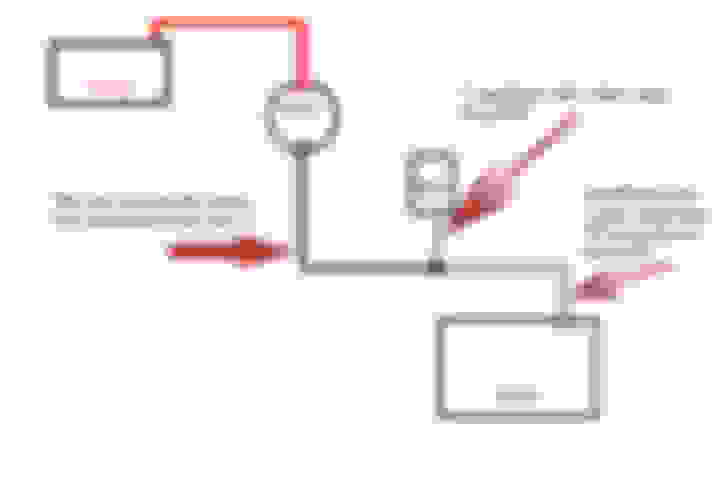
In the above diagram of the components of a relay, it is easy to see what is happening. This is a standard Bosch style SPDT (single pole, double throw) relay that is used by car stereo shops for alarms and such, for controlling lights, pumps, air compressors, etc. When you hear things clicking in your dash; those are relays. The factory relays do not have the same terminals on them, but work the same way. You can see the major components are the magnetic coil, a spring, the plate, and the terminals. There are very few moving parts so relays are incredibly reliable and fail very seldom.
The relay in the diagram is at rest. In other words, there is no current flowing to the coil and thus the plate is allowing contact between terminals 30 and 87a. This is how the relay sits when its unused, sitting in your toolbox, etc. It needs a signal to engage. The magnetic coil is what makes the switch happen to turn something on, but it has to get a signal first. By applying a ground to 85 and power to 86, the magnetic coil becomes active and pulls the plate over to 87 and completed that circuit and therefore whatever is wired to the relay turns on. When either power or ground is removed from the coil, the plate is pulled back to 87a and away from 87 and the device being powered by the relay loses power and shuts off.
For example, lets say that you have a driving light that draws 20amps of power. There are very few switches that can handle that much power because generally the have to be so small, so instead of wiring the light from the battery to a switch, then from the other side of the switch to the light we will use a relay.
In the diagram, a lead from the battery would be hooked to 30. This is going to drive our light and allows us to provide the light with current directly from the battery safely. 87a will not be hooked to anything since we do not want the light on with the relay at rest. For power to one side of the coil we can use ignition power or jump a battery wire that was added to 30 over the 86. Using an ignition source would mean the relay will only operate, and power the light, when the key is on. Jumping from the 30 terminal would mean the relay can be engaged without the key on. 85 would run through a switch that is grounded on one side of the switch with the other side going to 85. When the switch was toggled, this would send a ground to the coil, it has power from jumping 30 or and ignition source, so the coil would pull the lever over to 87. This "closes" to circuit between 30 and 87 and sends power to the light that is hooked up there provided a strong power source directly from the battery.
Here is a video of the inside of a relay. Notice the "lever" moves across and makes contact with the other terminal when I apply power and ground to the coil. This is what allows your power antenna to rise, your doors to lock, or in this case.....the fuel pump to turn on. When I release power, the "lever" moves away and power is interrupted.
Essentially the same thing is happening with the COR. The main pole(the hinge area of the steel plate) and one side of the coil is being applied power by an ignition source. The ECM via the FC (fuel control??) is proving a low current ground to the other side of the coil and the fuel pump power wire is waiting for the relay to engage, pull the plate over, and send it power.
At rest, the pump has no power and thus does not run. When the ECM sends ground to the relay via the FC terminal the coil pulls the lever and power is sent to the pump.
There are three different options to wire to COR relay that I will cover.
#1 - Using the Stock COR Relay:
The stock 3.0 relay is located in the passenger kick panel and where the stock ECM is shown here.
You will need to remove the one bolt holding the bracket and it can be removed.
Everything is effectively wired for you already other than the ground signal from the 3.4 ECM to engage the coil and send power to the fuel pump. Ignition (W-R in 3.0 vehicles, W-L for 3.4 wiring) to both the main pole and the other side of the coil is there.
All that needs to be done is run a wire from the FC terminal of the ECM and connect it to the G-Y wire and the relay will engage to power the fuel pump. The will NOT turn on the fuel pump, unlike the 3.4 stock setup, when the key is on the ON position. Only when the key is in the crank position and then the relay will stay on while the key is in the ON position allowing the pump to run until the key is shut off.
The G-Y wire is also located in the IH1 (C1) plug in the kick panel in the 23 position (for my vehicle- yours may differ) and can be wired there and not at the relay itself.
#2 Using the 3.4 Relay:
The 3.4 setup is simpler as it doesn't require and input from anything else like the 3.0 does although both will work fine. I would expect that a replacement would also be cheaper than the 3.0 relay because of its simplicity as well if that ever came up.
In a Tacoma or 4Runner, the factory COR is located on the bottom of the fuse panel that is on the bottom of the dash on the driver's side. It is significantly smaller that the 3.0 COR as well.
It looks like this.
It is a very simple setup like the relay pictured above in the diagram except even more streamlined as it doesn't have a 5th terminal that is "normally closed" (87a). It is effectively power in, power out. Also, because this relay has no input from the starter and only ignition, the pump will run with the key only turned to the ON position and not have to wait till the crank position is engaged. Toyota obviously changed this for a reason but I of course have no idea why. Possibly the pump engaging at ON rather than waiting until crank allows the pump a small amount of time to build pressure before crank to provide faster starting? I have no idea.
To wire this, you would simply splice this to the wires on the 3.0 COR harness and replace the 3.0 COR
From the 3.0 harness the G-Y would go to the G-Y on the 3.4 relay harness. L goes to L-O of the 3.4 harness and W-R goes to W-L(both of them) of the 3.4 harness that is it. The FC will send a ground to the relay when the key is ON and cranking and the relay will switch the plate inside to send power to the pump.
#3 - Using a Bosch Style Relay:
If you have neither relay available, or you have a failure away from a parts store for Toyota replacement relays, a standard Bosch style relay can also be used. These are available at any stereo shop, auto parts store, etc. for about $5. I usually always carry a couple just in case.
Since all the relays are essentially doing the same thing, (switching power) we can use this easily as well.
First though, the relay is providing power to your fuel pump. Therefore it is obviously VERY important that it works. As with anything, there are quality products and cheap imitations. Quality relays are Bosch and Potter and Brumfield (P&B). Anything else should be avoided unless you are in a bind and that's all that is available.
A genuine Bosch will clearly have a label as will a P&B but I don't have one here to picture.
A cheap imitation will have no label.
Wiring the relay is simple as well for this option of wiring your fuel pump.
Here is the diagram again to follow along.
Again, at the 3.0 COR harness everything you need is there. The W-R ignition wire would go to 30 and 86(one side of the magnetic coil), the L-O wire to feed the fuel pump would go to 87, and the G-Y from the FC terminal of the ECM would go to 86. This will engage to relay when it receives a ground from the ECM telling it to turn on the fuel pump by charging the coil and pulling the lever over to "close" the circuit between 30 and 87. Thus, the fuel pump runs.
Wiring the Starter to Actually Work:
This is probably #2 on the list of most posted issues behind the COR. Really its a fairly simple thing to do but again, first it may be better to understand what going on if you are new to electrical systems.
When you crank the key, a 12+v electrical signal is sent to the starter via the small wire on top. The wire is going to a type of relay that closes the circuit between the large wire that runs directly to the battery and the motor inside the starter. This is a great example on a large scale of why relays are needed. Without a starter relay (called a solenoid and not exactly the same as a relay but close enough for this explanation), the wire and switch would be enormous running from the battery to the ignition switch and then back to the starter. Multiply that amount of extra wire by millions of feet, and you can see that a car company would spend a fortune on the wire. Also, switches would be extremely large in order to handle the current. With a relay, the same thing can be accomplished with a much smaller switch and smaller wire. The same principle applies to using the metal of a car as a ground "wire" rather than running grounds wires to everything.
Anyway, by taking out the 3.0 motor harness, we are eliminating the wire that runs to the starter from the key. That is why a wire was ran into the cab from the starter itself. Now is when it needs to be connected.
Inside the kick panel, in the IH1 plug-in pin #22 (mine-again yours may be different) is a B-W wire that is larger than the other wires. This is the wire from the key that sends a signal to the starter. Again, this is from the key!! With your voltage meter (don't use a test light on computer controlled cars) it should provide 12+v when the key is in the crank position. This wire need to be SOLDERED to the wire that you ran from the starter. Joining these two wires will allow the motor to crank when the key is turned as it should.
However, the ECM also needs to know that the motor is attempting to start. It gets this signal from the STA terminal on the ECM. SO when you are soldering the B-W wire and the wire you ran from the starter, also include a small wire to run the STA terminal of the ECM. This is all that needs to be done to complete the starter circuit for the swap.
Here is a diagram:
Using Adobe Acrobat to Decipher EWD's:
I could type 30 pages about how to use Acrobat to get through EWD's more efficiently but I had to do some screen records for work related stuff so I thought that I would make one for this as well.
I am not really good at this but for some reason, the quality sucks at either YouTube or Vimeo. You may have to right-click it and choose "go to Vimeo to watch in HD" to actually go to Vimeo and then right-click and enter full screen and make sure the scaling is off otherwise the resolution is terrible.
And I know that I referred to the OBD2 as the CEL in the video : oops:but I am not going to do it over.
WOW. Awesome write up man. Working on my wiring right now for my swap and your COR and starter explanations just cleared everything up for me. Thanks for helping us new swappers out.
Thanks for posting this. I'll be there in a short time. I'm waiting for exhaust crossover to comeback from Toyonlyswaps. I've already swap over the engine mount and heater hoses. I'm going to mod the fuel line today or tomorrow.
this should be made a sticky for sure!!! great write up im expecting this will help me a lot!!! thank you for doing this in such great detail. I know you have before said it seems like people are looking for an instruction manual instead of just looking through the posts, it seems like they will find one here great job!!!
Thank you for this write up, I used it to map out my wiring concerns. Also thank you for all the connector pin part numbers, the screenshot of the website helps a lot. I am ordering my pin connectors now.
Great write up, thank you for taking the time to do it.
I have one suggestion though, on your soldering technique, this is not the correct way to solder two wires together. The wires must be tinned first and then soldered together. I am in no way an expert but grew up with an electronics tech and this is how I was taught. Not trying to stir the pot, just don't want peoples solder joints to fail. (that resistance thing)
This may help: http://www.teamnovak.com/tech_info/h...-SPLICING-3800
I get what you are saying and I understand the process of tinning the wires. However, for me, when joining two wires to run parallel it is difficult to tin the wires and then twist them to ensure a tight fit BEFORE making the final melt. I use to do it the way as shown in the link in figure 10 in my car audio/alarm day. After some failures due to stress as the author points out I switch to the method I outlined without a failure that I recall.
Either should work but I like the idea of a physical bond (twisting) and then "cementing" the together with the solder.
I understand your concern on the stress, I usually use heat shrink tubing, I think that helps.
I notice that you are not a fan of crimp connectors, I would like to point out that every single pin connector on those plugs you installed the wires are crimped from the factory. The engineers must know something. I also use crimps with heat shrink built on them.
As I said, I'm no expert but I know what works for me.
Along the lines of protecting the connection (no matter what method you use) I always use dielectric grease on all connections , crimped and soldered. It will keep the oxygen out and prevent corrosion.
An aside, I used some LED clearance lights for tail lights on my Kawasaki Teryx and had to solder in some resistors (they have a solid strand wire) so I could have tail and brake lights. I doubled heat shrinked them and never had an issue and that thing got rode hard.
 07-31-2011, 10:50 AM
 My only knowledge is doing the swap only twice and that hardly qualifies me as an expert and I not pretending to be. There are things that I still do not understand, like the A/C system
  . Hopefully someone can add a good , detailed writeup on that someday on HOW it works and some good diagrams and pictures.
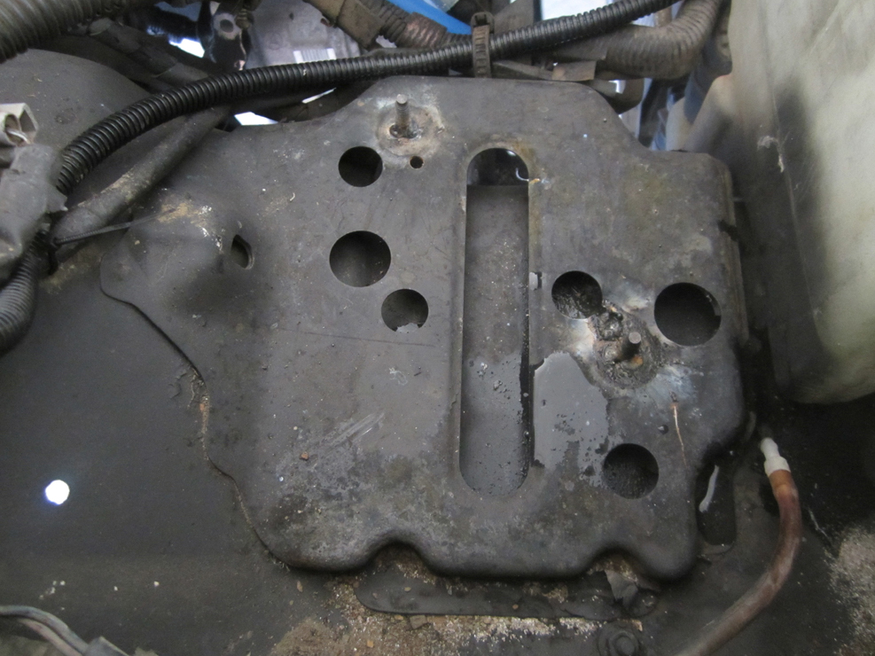
 Do it right.
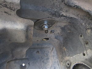


 great job!!!


