When you click on links to various merchants on this site and make a purchase, this can result in this site earning a commission. Affiliate programs and affiliations include, but are not limited to, the eBay Partner Network.
1985 22R-EC Electronically Controlled Transmission (ECT) indicator wiring diagram question: What are the pins and polarity that drive the two ECT dash indicators?
The 1st attached picture is of a Combination Meter (instrument cluster) from a 1985 Toyota pickup, which is similar to mine, that I pulled off google.
My truck's info: VIN: JT4RN66P7F5093420 MODEL: RN65L-PDCEA 557FQ41G282A340H
(the colored lines in the pic represent my "best guess" but I cannot find any documentation whatsoever to back me up). Does anyone have a complete wiring diagram for this ECT indicator circuit?
My goal is to replace the instrument cluster in my 1985 truck with one from a 1986 donor truck in order to get a tachometer while retaining the two ECT indicators (NORM & POWER).
It appears that all (but maybe just some???) of the pin designation are the same
.. however ...
in ALL the wiring diagrams that I can find, there are omissions (eg: no mention of the ECT indicators)
The 2nd attached picture is of a Combination Meter from a 1986 Toyota pickup... this is my pic of the actual instrument cluster that I pulled from a junk yard.
Donor truck's info: VIN: JT4RN63S2G5006713 MODEL: RN61L-MSEA O33KH11G292W56 Does anyone have a complete wiring diagram for a 1986 Combination Meter?
The 3rd attached picture is of a comparison table that I made in excel.
Please keep in mind that I'm a noob when it comes to these trucks
{ but I was an Electronics Technician in the Navy for 6 years... ET2 (SW), specializing in Comm & Crypto }
Any info I've provided is simply my best guess based on hours/days of research but SHOULD NOT be considered the gospel..... not yet anyway....
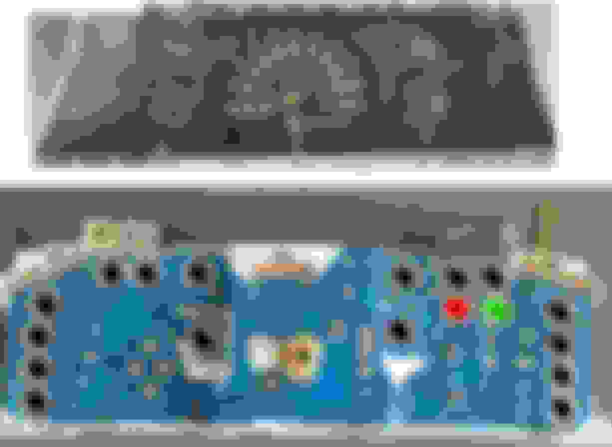
The last pic is the mod I made to the 1986 combination meter in an effort to retain the 2 ECT indicators.
PIC1:
PIC 2:
PIC 3:
Also, in order to keep the ECT dash indicators, I had to modify the 1986 left-most panel (outboard-driver side).
There were 2 unused indicator slots at the top, so I scratched off the black coating on the rear and have ordered some 1/4" vinyl letters to label them.
Here's a pic of the modification:
Thanks for an amazing forum. Any assistance with the 3 questions above is greatly appreciated!!!
I have a 1986 long bed pickup with a 22re and an a340h transmission. I think that my gauge is layed out just like your asking. I can take a picture of the font and back if that will help you??
 08-25-2016, 05:25 PM