TPS adjustment experts I need your help.
 09-10-2010, 01:24 PM
#1
Registered User
Thread Starter
TPS adjustment experts I need your help.
First and foremost I have searched and searched and printed off the directions from 4crawlers site. My truck has all of the symptoms of a bad or incorrectly adjusted TPS. I have the throttle body out of the truck and on my work bench, but I am having a really hard time figuring this out, nothing seems to be making any sense to me.
Okay I do not have any feeler gauges but I have a credit card for the .50mm reading. Here is what makes no sense to me at all.
As of right now I have not moved or loosened any bolts that hold the TPS in the TB or any set screws for the TB I simply have taken the TB with TPS still installed and placed it on my work bench.
When I hook up the multimeter to VTA and E2 the multimeter just shows 1 as in the amount of amps it is set to.
When I move the throttle while the multimeter is hooked up at VTA & E2 nothing happens it stays at the 1 amp setting showing.
Okay then I move the multimeter to IDL and E2 with no shim in place and I get this reading on the multimeter. 5.95
With the multimeter still at IDL and E2 I move the throttle to wide open throttle and I get this readout. 1.64
I am so freaking confused and I am about to go insane! According to 4Crawler the resistance number is supposed to go up when the throttle is moved to WOT why does my go down?
So here is the breakdown of my readings that I am getting.
VTA and E2 = Nothing just the 1 amp showing no matter what the throttle position is.
IDL and E2 = 5.95
IDl and E2 @ WOT = 1.64
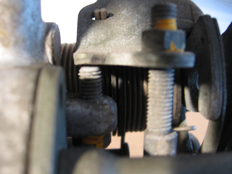
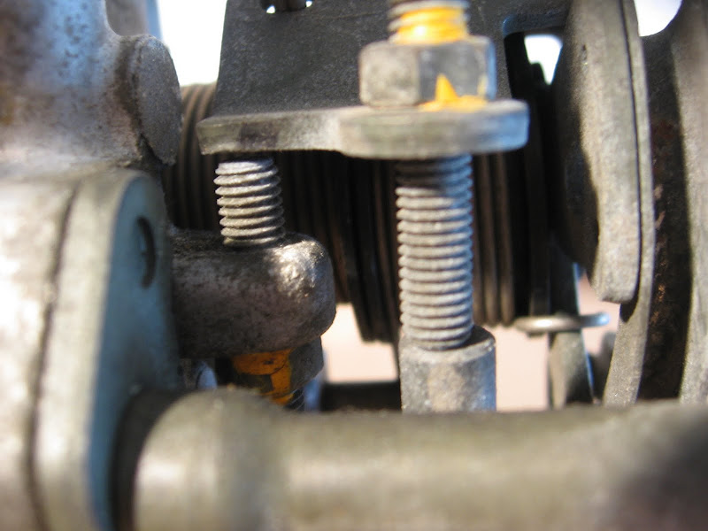
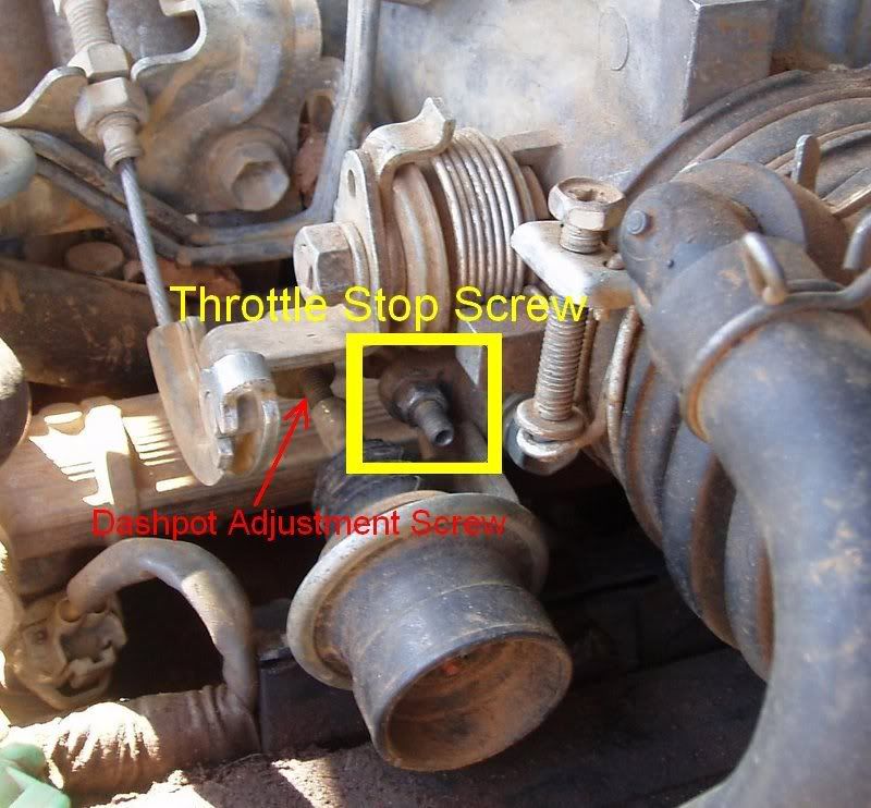
Also here are some pictures of how the set screws are setup. I have not adjust any of these.
The truck is taken apart and I am stuck until I can get this figured out.
On a side note I have noticed that this vacc line is plugged on the top of the TB does anyone know where it goes?
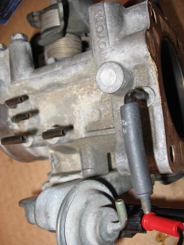
(it is plugged with a bolt and is right at the bright red connector in the picture.)
I also noticed that my 5th injector was unplugged? I plugged it back it back in, but why would it have been unplugged.
So sorry for all the questions I am just at a loss and hope to get this figured out before the parts store closes.
Chris
Okay I do not have any feeler gauges but I have a credit card for the .50mm reading. Here is what makes no sense to me at all.
As of right now I have not moved or loosened any bolts that hold the TPS in the TB or any set screws for the TB I simply have taken the TB with TPS still installed and placed it on my work bench.
When I hook up the multimeter to VTA and E2 the multimeter just shows 1 as in the amount of amps it is set to.
When I move the throttle while the multimeter is hooked up at VTA & E2 nothing happens it stays at the 1 amp setting showing.
Okay then I move the multimeter to IDL and E2 with no shim in place and I get this reading on the multimeter. 5.95
With the multimeter still at IDL and E2 I move the throttle to wide open throttle and I get this readout. 1.64
I am so freaking confused and I am about to go insane! According to 4Crawler the resistance number is supposed to go up when the throttle is moved to WOT why does my go down?
So here is the breakdown of my readings that I am getting.
VTA and E2 = Nothing just the 1 amp showing no matter what the throttle position is.
IDL and E2 = 5.95
IDl and E2 @ WOT = 1.64
Also here are some pictures of how the set screws are setup. I have not adjust any of these.
The truck is taken apart and I am stuck until I can get this figured out.
On a side note I have noticed that this vacc line is plugged on the top of the TB does anyone know where it goes?
(it is plugged with a bolt and is right at the bright red connector in the picture.)
I also noticed that my 5th injector was unplugged? I plugged it back it back in, but why would it have been unplugged.
So sorry for all the questions I am just at a loss and hope to get this figured out before the parts store closes.
Chris
Last edited by LifterCatcher; 09-10-2010 at 03:30 PM.
 09-10-2010, 01:39 PM
#2
Registered User
The plugged line goes to the EGR or the fuel pressure regulator. Offhand, not sure. I'd have to go and check my wife's 3.0 to be sure. But, if you see either of those components without a vac line or one that's plugged, that's where it goes.
Seems to me you're testing the TPS on the wrong terminals. Rather, you have them mixed up.
Seems to me you're testing the TPS on the wrong terminals. Rather, you have them mixed up.
09-10-2010, 01:52 PM
#3
Registered User
Thread Starter
With the TB sitting on the bench right side up or just like it would be installed in the truck E2 should be the lowest prong inside the plug IDL would be the next prong up or 2nd from bottom, and VTA would be the third prong up from the bottom?
I am going off of these pictures
Chris
I am going off of these pictures
Chris
09-10-2010, 01:57 PM
#4
O.k., this is what I would do. First, make sure it's set correctly by following the instructions on page EG2-242 of the FSM. You really have to have a .6mm/.024" feeler gauge to do that though. Or you can't set it correctly.
http://personal.utulsa.edu/~nathan-b...93throttle.pdf
Second, once you know for sure it's set correctly, recheck the resistance values given on page EG2-241, like it says to.
I can't tell you what that vacuum line that's plugged is for either off-hand. I'll look into that, but thook will probably beat me to it.
On the 5th injector matter, called the cold start injector, it's of no real benefit to leave it unplugged. I've heard some people think they can save gas by unplugging it. That's pretty silly though, and won't save but an ounce or two at best when starting the engine under cold conditions. And also makes starting much more difficult during very cold conditions.
Last edited by MudHippy; 09-10-2010 at 02:16 PM.
09-10-2010, 02:04 PM
#5
Registered User
Thread Starter
O.k., this is what I would do. First, make sure it's set correctly by following the instructions on page EG2-242 of the FSM. You really have to have a .8mm/.031" feeler gauge to do that though. Or you can't set it correctly.
http://personal.utulsa.edu/~nathan-b...93throttle.pdf
Second, once you know for sure it's set correctly, recheck the resistance values given on page EG2-241, like it says to.
http://personal.utulsa.edu/~nathan-b...93throttle.pdf
Second, once you know for sure it's set correctly, recheck the resistance values given on page EG2-241, like it says to.
09-10-2010, 02:08 PM
#6
Registered User
Shouldn't the black connector on your multimeter be plugged into the COM port? The red one is then moved between the upper two for resistance or voltage measurements, depending on which one you are doing.
I think you have the probes plugged into the multimeter incorrectly.
Mike
I think you have the probes plugged into the multimeter incorrectly.
Mike
09-10-2010, 02:15 PM
#7

Last edited by MudHippy; 09-10-2010 at 02:18 PM.
Trending Topics
09-10-2010, 02:25 PM
#8
Registered User
Thread Starter
Shouldn't the black connector on your multimeter be plugged into the COM port? The red one is then moved between the upper two for resistance or voltage measurements, depending on which one you are doing.
I think you have the probes plugged into the multimeter incorrectly.
Mike
I think you have the probes plugged into the multimeter incorrectly.
Mike
Thanks for everyones help on this I am off to the parts store real fast to pick up some feeler gauges just to make sure. Be back in 10.
Last edited by LifterCatcher; 09-10-2010 at 02:27 PM.
09-10-2010, 03:18 PM
#9
Registered User
Thread Starter
ok back from the parts store with some feeler gauges.
looking at the FSM I wanted to start from the beginning on page EG2-241 Step number 2 it says
2. CHECK THROTTLE VALVE
(a) Apply vacuum to the throttle opener.
(6) Check that there is no clearance between the throttle
stop screw and throttle lever when the throttle valve
is fully closed.
However I am finding that there is a gap between the throttle stop screw and the plate that it is supposed to touch.
(you can see the gap here, do I need to adjust the throttle stop screw so there is ZERO gap.
So does this mean the base setting for the TPS is off? Could this be throwing all of the other readings off?
On page EG2-242 is says to
4. IF NECESSARY, ADJUST THROTTLE POSITION
SENSOR
(a) Loosen the two screws of the sensor.
(b) Apply vacuum to the throttle opener.
(c) Insert a thickness gauge (0.60 mm or 0.024 in.) be�
tween the throttle stop screw and lever, and connect
the ohmmeter to terminals IDL and E2.
(d)Gradually turn the sensor clockwise until the ohm�
meter deflects, and secure the sensor with the two
screws.
what do they mean by deflects? does that mean ZERO?
Last edited by LifterCatcher; 09-10-2010 at 03:29 PM.
09-10-2010, 04:13 PM
#10
Registered User
The gap will definitely throw readings off. What it looks like to me is the throttle opener is still engaging the linkage.......meaning, if you have vacuum applied to the opener, it does not look likes it's responding to vacuum and therefore the stop screw is not being allowed to rest on the stop. Manually move the opener piston away from the linkage. Then, see if the stop screw comes to rest.
What it means by deflect is that the meter simply changes reading from what was previously reading. Sometimes it's necessary to adjust or find a different point at which the TPS idle contact will register due to variances in manufacturing or just plain wear on the unit. So, a slightly thicker guage is used in this case. The same end can be achieved, however, by simply starting the engine, and with the sensor loose enough to pivot, simply turn it until the IDL contact will register noted by a drop in RPM. This is the point at which the ECU is reading the throttle plate's idle position.
I still haven't look at my wife's vehicle. But, I will shortly and get back later. I'm cleaning freezers, eh.
Um, btw......didn't there used to be a pic of the multimeter up here? I any case, since all your testing for is continuity, with the probes reversed, you'll still get a reading. The contacts are not polarized until a charge is placed on them. IOW's, with the harness connected, you will have voltage from the Vcc terminal and a ground supplied by the E2. However, with your meter, the charge from the meter's battery can be supplied from either end of the IDL circuit. Likewise with the ground. It's like testing a strand of wire. Either end can be voltage and either end can be ground. Make sense?
Last edited by thook; 09-11-2010 at 12:10 AM.
09-10-2010, 05:11 PM
#12
I am glad somebody that has experience with the vacuum actuated throttle opener and what to do with the TPS as far as adjusting it with one is ready to take the wheel(so to speak). Mine has no such contraption. Old pics from a thread of a different color.
Soooo much simpler...
So I'm going to have to take a back seat for the duration. I haven't had a chance to fiddle with that type of throttle body setup. And quite frankly am bewildered as to what comes next. Fascinating though...I must say.

I can't help but brag that it was alot easier to check for continuity when setting the IDL contact position on mine. How's that? I used my Fluke multimeter. It has an audible "beep" when set to check continuity, which pretty much means a blind man could do it with a Fluke(too bad you don't have one too).

Last edited by MudHippy; 09-10-2010 at 05:16 PM.
09-10-2010, 05:14 PM
#13
Registered User
I think it has something to do with the air conditioning. I know whenever my A/C compressor engages; vacuum is released on the opener causing idle to raise. That's the only time I notice the opener being 'used' so to say.
Any auto parts store will have a cheap vacuum pump available, either as part of a brake bleed set or separate - some stores might even loan them out.
Last edited by dieselloco427; 09-10-2010 at 05:16 PM.
09-10-2010, 05:33 PM
#14
Nada. No A/C. Sometimes a little AC/DC though.
Or another way that I can think of would be to put the key in the ignition and turn it to the "ON" posistion. Then jump the check connectors(TE1 & E1) and have someone tell you, or check for yourself to see(a well placed mirror may save you a good deal of time there), when the check engine light goes from code 51 to the steady-flashing phase. At that point the IDL contact points will be set correctly/closed.
Enough out of me. I hush-up now.
Enough out of me. I hush-up now.
09-10-2010, 06:04 PM
#15
Registered User
Thread Starter
09-10-2010, 06:14 PM
#16
Registered User
Thread Starter
Here is what I am not understanding.
When the throttle is closed all the way resting against the throttle stop plate the multimeter should read 0.00 correct because the switch is closed no resistance no signal. Then when you put the feeler gauge between the stop screw and the plate the multimeter should read a number because the TPS is sensing that the throttle is opening correct? However when I place the multimeter on IDL and E2 with no feeler gauge installed I am getting a reading of 5.90 ( with simulated vacuum applied)
So does this mean that the TPS is out of adjustment? And it needs to read 0.00 when the throttle is all the way closed and then show a reading when the feeler gauge is installed?
Also I am not understanding my when I connect VTA and E2 I am getting NO reading at all? The multimeter does not show any numbers.
Also this is tested with two different multimeters, I went out to the store and got a new one to make sure the one I had was not bad and both multimeters are showing the same readings. I am so damn confused,
09-10-2010, 06:15 PM
#17
Registered User
Nada. No A/C. Sometimes a little AC/DC though.
Or another way that I can think of would be to put the key in the ignition and turn it to the "ON" posistion. Then jump the check connectors(TE1 & E1) and have someone tell you, or check for yourself to see(a well placed mirror may save you a good deal of time there), when the check engine light goes from code 51 to the steady-flashing phase. At that point the IDL contact points will be set correctly/closed.
Enough out of me. I hush-up now.
I'm inclined to believe the thing was only an improvement made by Toyota to fine tune start up and curb idle. I used to believe it was only for vehicles equipped with automatic trannies until I started seeing 5spd's (later than yours, Mudhippy) had them also. It's not for the A/C as that already has it's own device (a switching valve on the pass. wheel well) to compensate for idle drag. If you, dieselloco, are seeing vacuum release on the opener when the A/C compressor is running, it can only be an effect of the drag on the engine. IOW's, the throttle opener is in no way connected to the A/C system. It's actuated and controlled entirely by the engine running and creating vacuum as it does so. And, of course, the amount of vacuum pull on the opener is depends on manifold pressure. Once the throttle is engaged by the cable, though, the opener becomes moot.
BTW, my mistake....that block off port for your TB is supposed to be blocked off. It is on my wife's vehicle/3.0. Not sure why it's even there except for some kind of gadgetry not available to ordinary folk........like a flux capacitor or something.
Last edited by thook; 09-10-2010 at 06:25 PM.
09-10-2010, 06:25 PM
#18
Registered User
Thread Starter
Hahaha....no need for that hush up business. The TB's with throttle openers are no different for adjustments than one without. The throttle opener is the only difference. You just have to get the piston out of the way for the throttle plate to fully close. I usually suck on it until the piston draws in and then clamp the hose with some small vice grips. Holds it back quite well.
I'm inclined to believe the thing was only an improvement made by Toyota to fine tune start up and curb idle. I used to believe it was only for vehicles equipped with automatic trannies until I started seeing 5spd's (later than yours, Mudhippy) had them also. It's not for the A/C as that already has it's own device (a switching valve on the pass. wheel well) to compensate for idle drag. If you, dieselloco, are seeing vacuum release on the opener when the A/C compressor is running, it can only be an effect of the drag on the engine. IOW's, the throttle opener is in no way connected to the A/C system. It's actuated and controlled entirely by the engine running and creating vacuum as it does so. And, of course, the amount of vacuum pull on the opener is depends on manifold pressure. Once the throttle is engaged by the cable, though, the opener becomes moot.
BTW, my mistake....that block off port for your TB is supposed to be blocked off. It is on my wife's vehicle/3.0. Not sure why it's even there except for some kind of gadgetry not available to ordinary folk........like a flux capacitor or something.
 Thook Also I am not understanding when I connect VTA and E2 I am getting NO reading at all? The multimeter does not show any numbers. Any idea why this is?
09-10-2010, 06:29 PM
Thook Also I am not understanding when I connect VTA and E2 I am getting NO reading at all? The multimeter does not show any numbers. Any idea why this is?
09-10-2010, 06:29 PM
#19
Registered User
With the TB sitting on the bench right side up or just like it would be installed in the truck E2 should be the lowest prong inside the plug IDL would be the next prong up or 2nd from bottom, and VTA would be the third prong up from the bottom?
I am going off of these pictures
Chris
I am going off of these pictures
Chris
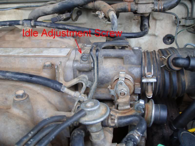
Which direction is your throttle sensor facing? Are the terminals pointing toward the manifold end of the throttle body or toward the intake end? In the illustration from 4crawler's page, the sensor is pointing toward the intake end of the throttle body. On yours, considering the year, I'm betting it's towards the manifold end, no?
09-10-2010, 06:36 PM
#20
Registered User
Thread Starter
Let me ask you this.......
Which direction is your throttle sensor facing? Are the terminals pointing toward the manifold end of the throttle body or toward the intake end? In the illustration from 4crawler's page, the sensor is pointing toward the intake end of the throttle body. On yours, considering the year, I'm betting it's towards the manifold end, no?
Which direction is your throttle sensor facing? Are the terminals pointing toward the manifold end of the throttle body or toward the intake end? In the illustration from 4crawler's page, the sensor is pointing toward the intake end of the throttle body. On yours, considering the year, I'm betting it's towards the manifold end, no?
Do not even tell me it is installed BACKWARDS! OR this would mean that the terminals are actually upside down compared to 4crawlers page, and my E2 would actually be the very top terminal and not the bottom? This would also explain why I am not getting a reading when I thought I was connecting VTa to E2.
Last edited by LifterCatcher; 09-10-2010 at 06:41 PM.


