
please help with indicator light wiring
 02-25-2009, 02:57 PM
#1
Registered User
Thread Starter
Join Date: Feb 2008
Location: Western, MA
Posts: 212
Likes: 0
Received 0 Likes
on
0 Posts
please help with indicator light wiring
I hooked up a set of strobes that i got for free for my truck. I correctly wired them and they worked. Then later i decided to add an indicator light. I thought i knew how to wire it correctly but i was wrong.
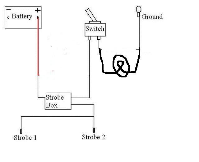
The first picture is of the strobes correctly wired by themselves.

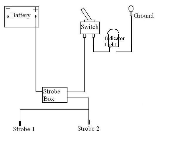
The second pic is how i thought the indicator light was supposed to be wired but was incorrect. When i did it this way the light was on when in the off position and off when in the on position, this is the opposite of how it's supposed to be. Please help.

The first picture is of the strobes correctly wired by themselves.
The second pic is how i thought the indicator light was supposed to be wired but was incorrect. When i did it this way the light was on when in the off position and off when in the on position, this is the opposite of how it's supposed to be. Please help.


 03-05-2009, 05:40 PM
#4
Registered User
Thread Starter
Join Date: Feb 2008
Location: Western, MA
Posts: 212
Likes: 0
Received 0 Likes
on
0 Posts
i did it this way and the wire that ran from the battery and does a 90 degree turn and goes to the indicator light melted. Now the 4runner won't start. nothing works, i checked all the fuses and there fine. It won't jump start. my friend said the battery could have shorted and died beyond fix. Should i get a new battery please help. i messed up.
03-05-2009, 06:10 PM
#5
Registered User
Join Date: Mar 2008
Location: Temecula Valley, CA
Posts: 12,723
Likes: 0
Received 4 Likes
on
4 Posts
all I did was move the switch from the ground side of the strobe to the hot side.
then put the indicator in parallel across the strobe controller.
I'm going to check over what I posted and see if I can figure out what may have happened.
then put the indicator in parallel across the strobe controller.
I'm going to check over what I posted and see if I can figure out what may have happened.
03-05-2009, 06:16 PM
#6
Registered User
Join Date: Mar 2008
Location: Temecula Valley, CA
Posts: 12,723
Likes: 0
Received 4 Likes
on
4 Posts
I find it hard to believe that an indicator lamp wired to a switch in order to be grounded has rendered your truck immobile.
I'm still contemplating though....
I'm still contemplating though....

Trending Topics
03-06-2009, 10:33 AM
#8
Registered User
Thread Starter
Join Date: Feb 2008
Location: Western, MA
Posts: 212
Likes: 0
Received 0 Likes
on
0 Posts
i wired it the way you said as the second option you gave second option, and one of my friends said it was a correct way to do it. But the insulation on the wire marked in red like fryed and melted and crumbled off.

I replaced the battery and it started again so thats all fixed. But what did i do wrong? was the wire not thick enough
I replaced the battery and it started again so thats all fixed. But what did i do wrong? was the wire not thick enough
03-06-2009, 12:26 PM
#9
Registered User

Join Date: Sep 2007
Location: San Francisco East Bay
Posts: 8,254
Likes: 0
Received 822 Likes
on
649 Posts
The wire melted because it had "way too much" current, which was because it was shorted to ground. If, when you installed the indicator, you somehow shorted the indicator, that would do it. (AbeCedarian's diagrams are fine.)
Take your ohmmeter (no ohmmeter? They're what, $3 at Harbor Freight? Of course you have one, you wouldn't be doing wiring without it.) and measure the resistance from the old battery connection (where the indicator and strobe box come together on the battery side) and measure the resistance to ground. You should get about 3-10 ohms. If it is "infinite" something else got fried (probably the switch). But if it's 0-1 ohms, something is shorted. Don't connect it to a battery until you find out what is shorted, or if you do, call 911 first.
Personally, I think you should have left it the way you had it the first time; indicator illuminated means strobes are off. (It also means strobes are correctly wired.) But you should get what you want.
03-07-2009, 09:44 AM
#11
Registered User
Thread Starter
Join Date: Feb 2008
Location: Western, MA
Posts: 212
Likes: 0
Received 0 Likes
on
0 Posts
would it be safe to just rewire the strobes again without the indicator? My friend who is going to school to become a mechanic wired the strobes and i thought i could handle wiring the indactor light, but i guess not. if i were to wire the indicator light again. what should i do differently.
03-07-2009, 09:52 AM
#12
Registered User
Join Date: Feb 2006
Location: Barrie, Ontario CANADA
Posts: 1,730
Likes: 0
Received 0 Likes
on
0 Posts
You melted because you have the light in parallel with the strobe box. This cuts your resistance through the circuit causing the melting because of the high current draw. Your indicator light should be in between the switch and ground or between battery and strobe box. Resistance in series adds together (lowers current) in parallel it increases current.
Last edited by Flash319; 03-07-2009 at 09:56 AM.
03-07-2009, 10:00 AM
#13
Registered User
Thread Starter
Join Date: Feb 2008
Location: Western, MA
Posts: 212
Likes: 0
Received 0 Likes
on
0 Posts
You melted because you have the light in parallel with the strobe box. This cuts your resistance through the circuit causing the melting because of the high current draw. Your indicator light should be in between the switch and ground or between battery and strobe box. Resistance in series adds together (lowers current) in parallel it increases current.
03-07-2009, 10:09 AM
#14
Registered User
Join Date: Feb 2006
Location: Barrie, Ontario CANADA
Posts: 1,730
Likes: 0
Received 0 Likes
on
0 Posts
Just cut the wire that is going from the switch to ground and stick the light in between. So the wire goes from the switch to one side of the indictor light then from the other side of the indicator light to ground.
 03-07-2009, 10:26 AM
#16
Registered User
Join Date: Feb 2006
Location: Barrie, Ontario CANADA
Posts: 1,730
Likes: 0
Received 0 Likes
on
0 Posts
Put a fuse between the battery and the strobe box.
Some simple DC electrics:
Current flows through things to make them work. So + electrons are trying to get to the - electrons. In doing this they do "work". So you put stuff between the path to make the "thing" work. The more stuff you have in between the more resistance the electrons have to fight through to get to the their lovers. This lowers the current going through the circuit.
If you want to switch the path on and off you put a switch in between. Then only when the switch is on you have current flowing. Anything between will not come on until the switch is closed allowing current to flow. If you want to limit the current you put a "fuse" in and thus if the current gets to high it blows open.
03-07-2009, 03:14 PM
#17
Registered User
Join Date: Sep 2007
Location: San Francisco East Bay
Posts: 8,254
Likes: 0
Received 822 Likes
on
649 Posts
The strobe probably pulls about 6amps or thereabouts, so it is about 2 ohms. (Because of the way it's power supply works it might not measure that way with an ohmmeter, but the current draw is the issue.) An indicator lamp, even a really bright one, pulls about 0.03 to 0.100 amps. So it's effectively 120 to 400 ohms. If you wire them in series as suggested, you will have about 122 to 402 ohms, so the total current you could get would be 0.03 to 0.100 amps. The indicator lamp would come on, but the strobes would never work. (Note that he originally had them wired in series WHEN THE SWITCH WAS OFF. As predicted, the indicator came on when the strobes were not working.)
The reason the wire melted is that his indicator lamp was not 120 to 400 ohms, it was somewhere very close to zero ohms. Either the fixture was shorted, or more likely, during the wiring the two leads to the indicator were touched together. That's all it takes.
Perhaps what Flash319 was thinking of was hooking two really big current draws in parallel on the same wire. If you hooked a 6amp strobe in parallel with a set of off road lights pulling 15amps, now you're up to 21 amps. That takes a pretty big wire, and if your wire is too small it will smoke. But an indicator is never SUPPOSED to pull that kind of current.
03-07-2009, 03:55 PM
#18
Registered User
Join Date: Mar 2008
Location: Temecula Valley, CA
Posts: 12,723
Likes: 0
Received 4 Likes
on
4 Posts
This will not work.
What is posted amounts to rounding the strobe controller through the indicator lamp which, won't work due to the voltage on the system and the internal resistance of both the indicator lamp and the strobe controller. Okay, well it might work if the strobe controller and lamp were both rated for 6v systems... but since we're talking about modern things and not an old VW Type I... I'm fairly sure I'm correct here.
If you want an indicator to light with the strobe, they must be wired in parallel so each gets the voltage they require and each ground independently of each other... which they do in spite of the common connection with the switch: if the indicator failed, the strobe would still work and if the strobe failed the indicator would still work.
Last edited by abecedarian; 03-07-2009 at 03:56 PM.
03-07-2009, 05:29 PM
#19
Registered User
Thread Starter
Join Date: Feb 2008
Location: Western, MA
Posts: 212
Likes: 0
Received 0 Likes
on
0 Posts
well what happened was the indicator light would randomly work sometimes, but not other times. when you say "during the wiring the two leads to the indicator were touched together." what does that mean?
03-08-2009, 12:43 PM
#20
Registered User
Join Date: Sep 2007
Location: San Francisco East Bay
Posts: 8,254
Likes: 0
Received 822 Likes
on
649 Posts
If the two leads of the indicator are touched together, the 12v will not go through the indicator, it will go through that short circuit (0 ohms) to ground.12v / 0 ohms = infinite current (or at least enough to melt wire).
If you connect the two prongs of a wall outlet together with a piece of good conducting metal (I recommend a hair pin), what happens? A heck of a pop, and as the current is heading North to infinite the circuit breaker pops at 20amps saving you, your house, etc. (20 amps, if you could limit it to that, will easily turn a hairpin white hot!) That's why you needed (and still need) a fuse in your circuit.


