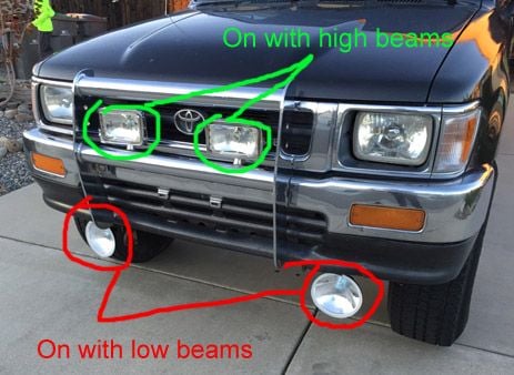
How to Make Fog Lamps Come on w/Low Beams?
#21
No dice. But my wires are the same colors as in the schematic you provided. I hooked up the relay and everything like your image indicated. Here's what happens; The fog lights come on with my headlights and turn off with my headlights, but they stay on during low beam and high beam.
I think I noticed something; Once I turn on my head lamps the low beams seem to stay on even while the high beams are switched on. And one of the wires always seems to be energized. I'm guessing that's the red/black.
Perhaps if I just connected 86 to red/green and 85 to red/black? Would that yield the results I want? I don't know. I'm just playing with wires here.
Can't think of a workaround now...
The red-back will always have 12V when headlights are on. The stalk / dimmer switch selects which filament gets the ground, the LB or HB.
#22
Well, even though I haven't been able to get this working as I'd like, I appreciate your time and efforts helping me think this through. At least the fog lights come on with the headlights. Shoot me if they don't go off when the high beams come on. I don't think any officers will ticket me for that and I don't think it's a big deal. I'll live with this setup as is. :-)
Here's what I've been withholding: I have a second set of lights installed (driving lights), but not wired up. I was hoping to have these ones automatically come on when the high beams come on. Obviously that will not be possible. My second most preferable option is to have them wired...
Now I echo these sentiments also. I'll be leaving the fog lights as they are now. But the driving lights I'll put on a switch.
Thanks for your help, guys!
Here's what I've been withholding: I have a second set of lights installed (driving lights), but not wired up. I was hoping to have these ones automatically come on when the high beams come on. Obviously that will not be possible. My second most preferable option is to have them wired...
Thanks for your help, guys!
#23
Come to think of it, stock headlight wiring is flawed. Clean, Robust, plug-and-play and inexpensive fix would be an H4 conversion harness (search "H4 harness conversion").
Once you do the conversion, You can do exactly what you want:
Fogs on with Low-Beams ONLY
Driving lights on with High-beam ONLY.
There would be no more bleeding "ground" through bulb filament.
You wire lights to back of bulb connector same way a I drew.
Once you do the conversion, You can do exactly what you want:
Fogs on with Low-Beams ONLY
Driving lights on with High-beam ONLY.
There would be no more bleeding "ground" through bulb filament.
You wire lights to back of bulb connector same way a I drew.
#24
Come to think of it, stock headlight wiring is flawed. Clean, Robust, plug-and-play and inexpensive fix would be an H4 conversion harness (search "H4 harness conversion").
Once you do the conversion, You can do exactly what you want:
Fogs on with Low-Beams ONLY
Driving lights on with High-beam ONLY.
There would be no more bleeding "ground" through bulb filament.
You wire lights to back of bulb connector same way a I drew.
Once you do the conversion, You can do exactly what you want:
Fogs on with Low-Beams ONLY
Driving lights on with High-beam ONLY.
There would be no more bleeding "ground" through bulb filament.
You wire lights to back of bulb connector same way a I drew.
#25
#27
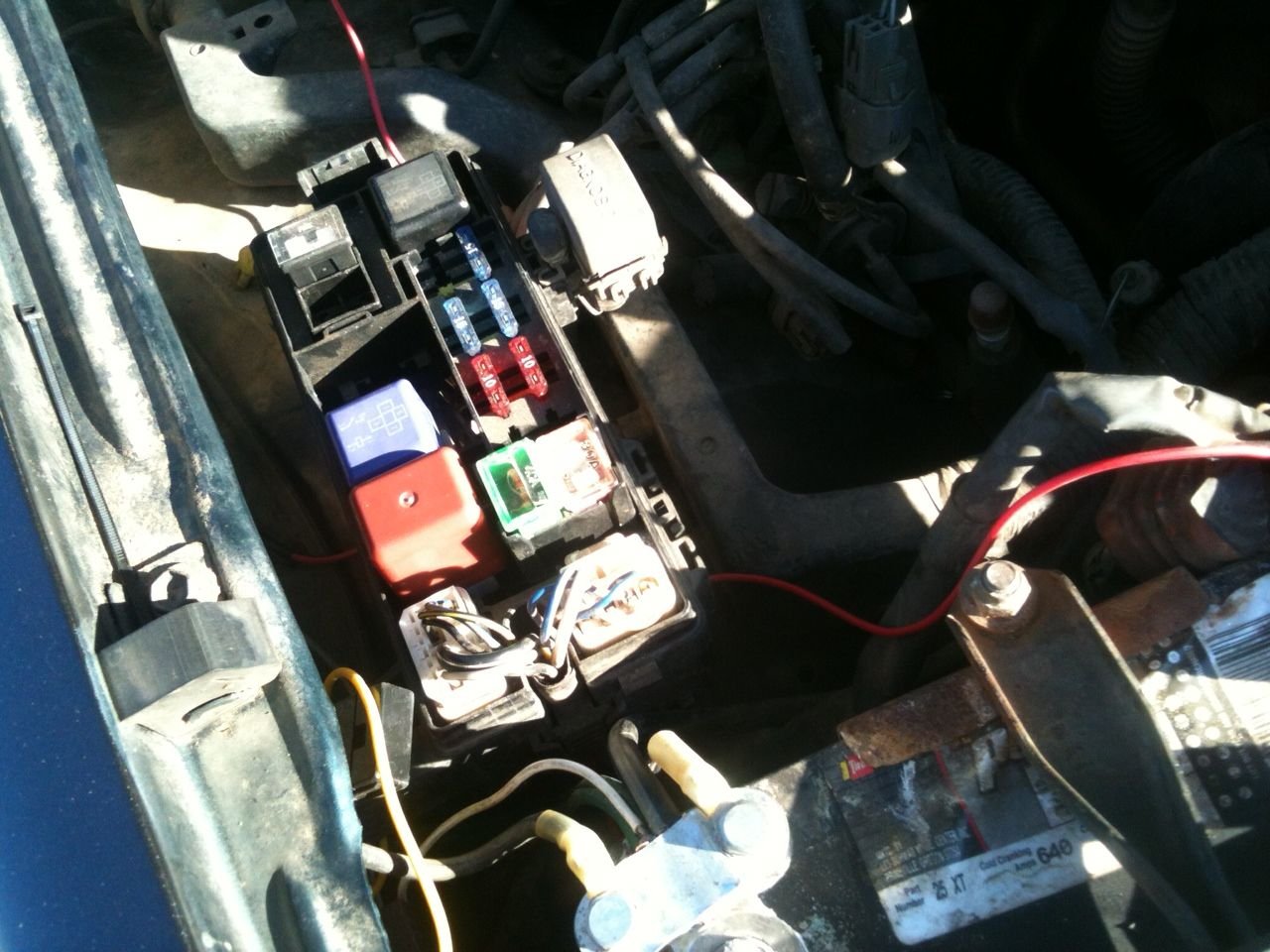
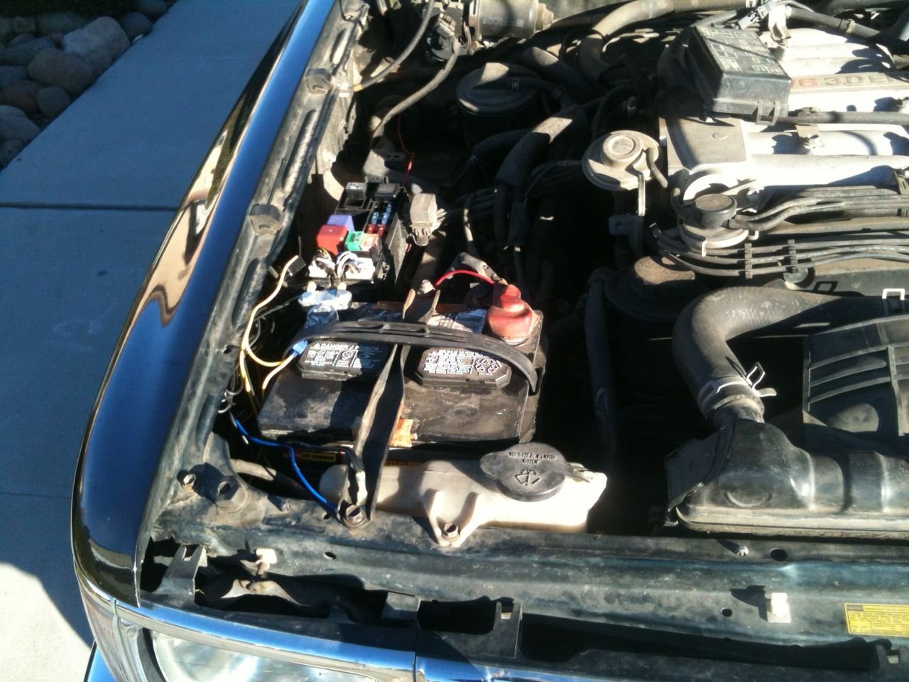
Upon having a second look at the schematic, saw that my theory of grounding through bulb filament is incorrect. Wanna double-check your wiring? Did you wire pins 85 and 86 directly to wires behind the bulb connector? Post a pic?
Last edited by RAD4Runner; 11-23-2015 at 10:59 AM.
#28
#29
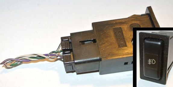
I just picked up this switch, but I don't know how to wire it in. I see 4 wires. One for the ground. One to slot 86 on the relay. And one to a 12v supply. Right? But where does the 4th one go? This is per Hella's instructions for THEIR aftermarket switch. But since I'm using a factory Toyota switch how do I know which wires on the pigtail to connect to? :-) All expertise is appreciated.
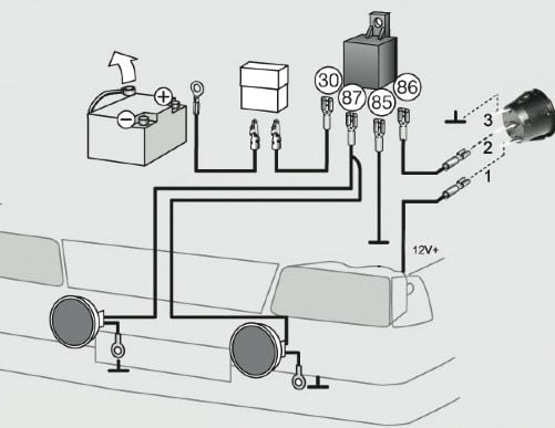
Here's what I'm shooting for: This switch will be used with the driving lights (green circles in the image I already posted). The 12v supply I will tap will probably be the headlights. I've given up on the low beam:high beam thing.
Last edited by Brock Lee; 11-23-2015 at 04:25 PM.
#30
Registered User
Join Date: Sep 2007
Location: San Francisco East Bay
Posts: 8,252
Likes: 0
Received 820 Likes
on
648 Posts
That's what a multimeter is for (even if you HAVE the instructions, you'll still check it).
Are you sure (or do you know at all if) this is a lighted switch? Your diagram calls for a SPST (single-pole, single throw) switch. I'm guessing you have a SPDT switch with an incandescent (not polarized) lamp that shares one of the switch conductors. You can tell which pair is the lamp; it should be "around" 20-40 ohms, and not change with switch position. Then just work out which pairs open and close with the switch actuation.
Are you sure (or do you know at all if) this is a lighted switch? Your diagram calls for a SPST (single-pole, single throw) switch. I'm guessing you have a SPDT switch with an incandescent (not polarized) lamp that shares one of the switch conductors. You can tell which pair is the lamp; it should be "around" 20-40 ohms, and not change with switch position. Then just work out which pairs open and close with the switch actuation.
#31
Registered User

I just picked up this switch, but I don't know how to wire it in. I see 4 wires. One for the ground. One to slot 86 on the relay. And one to a 12v supply. Right? But where does the 4th one go? This is per Hella's instructions for THEIR aftermarket switch. But since I'm using a factory Toyota switch how do I know which wires on the pigtail to connect to? :-) All expertise is appreciated.
Ground those 2 wires, and apply 12V to each of the wires and see what happens when you activate or de-activate the switch, a multi-meter will help.
#32
Ideally, this is the information I need:
1. White w/black stripe wire goes to...
2. Green wire connects to...
3. Purple wire connects to...
4. Orange/Peach wire connects to...
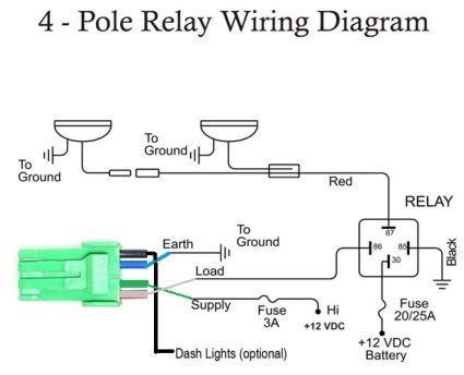
I have no clue here. I only know that I need a wire connected to the relay, ground, 12v power, and maybe dash lights or something else. I can understand that. Looks like I'll have to connect stuff up and see what happens... sans multimeter.
I appreciate the advice, fellas! If anyone else has expertise I'd be happy to listen to it!
Looks like this diagram could be helpful to me, even if the colors are different.
Last edited by Brock Lee; 11-24-2015 at 08:50 AM.
#33
Registered User
Join Date: Sep 2007
Location: San Francisco East Bay
Posts: 8,252
Likes: 0
Received 820 Likes
on
648 Posts
No excuse for that. http://www.harborfreight.com/7-funct...ter-90899.html Not to be unnecessarily harsh, but no one has any business messing with electrical items without some sort of multimeter. You can get hurt, start a fire, fry your whole electrical system ...
But not to worry, all you need is a ... (yup!) ... multimeter. Or maybe a friend with a multimeter.
When you get your multimeter, this may help you get started: http://www.cygnusx1.net/Media/Supra/...otaTech/h4.pdf
Last edited by scope103; 11-24-2015 at 10:37 AM.
#34
Haha! And I want a red one made by Ferrari. But up to now they're not manufacturing them. I'd settle for solid gold.
I hear ya. I am hoping for the opposite. We're in the internet age and I'm hoping somebody out there knows this information or has had this same issue and knows the answer. That's why I've posted as much information and pics as I can.
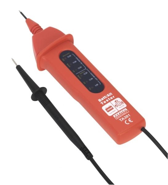
No multimeter, but I own something that looks like this thing:
#35
Registered User
Join Date: Sep 2007
Location: San Francisco East Bay
Posts: 8,252
Likes: 0
Received 820 Likes
on
648 Posts
So spring for the 6 bucks. You'll be (very) glad you did.
Thread
Thread Starter
Forum
Replies
Last Post
zz_denis
95.5-2004 Tacomas & 96-2002 4Runners
2
09-06-2015 03:43 PM


