
Complete brake system refresh and now mushy pedal?
 04-01-2013, 07:04 PM
#41
Registered User
i'm just saying....i almost want to call bull˟˟˟˟ on you guys, cause nothing i've seen shows the spring are on backwards from the pics he gave. even after you've explained it i still dont see the springs wraps you're talking about in a single pic.
dont get mad that i am questioning. mostly i'm just trying to get proved wrong for learning purposes.....i'm sure i'm missing something.
dont get mad that i am questioning. mostly i'm just trying to get proved wrong for learning purposes.....i'm sure i'm missing something.
Take a long gander at the pic's again and then look at the diagram pic and if your (sure your still missing something), then your challenge of bull**** is just a moot point.


 and only 3 springs.
04-01-2013, 07:47 PM
and only 3 springs.
04-01-2013, 07:47 PM
#43
Registered User
Then the springs are in correctly?
04-01-2013, 09:43 PM
#44
Registered User
Join Date: Feb 2011
Location: Hammond, LA
Posts: 384
Likes: 0
Received 0 Likes
on
0 Posts
my point is i dont see a single spring wrap in any of those pics. which pic do you see a spring wrap in?
edit....ok after looking at the diagram again...i can see where reversing the springs would move the rear axle backwards like the diagram shows.
so basically the OP needs to make sure the spring wrap is in the rear and not the front......if.....his rear axle is on top of the springs and not sitting on the bottom. making sense now. sorry just trying to make sense of this so everyone else can too.
Last edited by maachine; 04-01-2013 at 09:50 PM.
04-01-2013, 09:54 PM
#45
Contributing Member
Join Date: Mar 2003
Location: COTKU,Ontario,Canada
Posts: 11,334
Likes: 0
Received 0 Likes
on
0 Posts
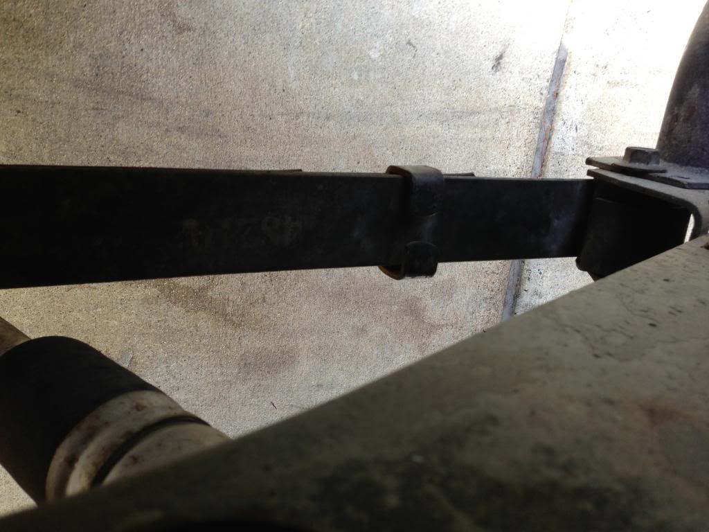
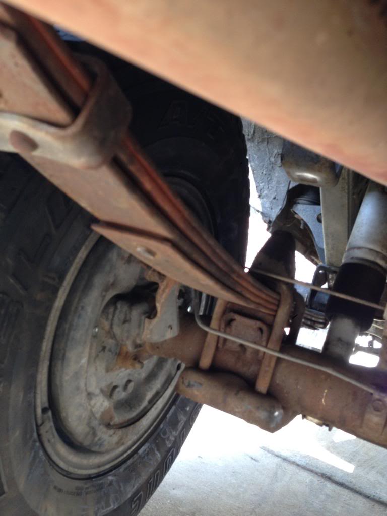
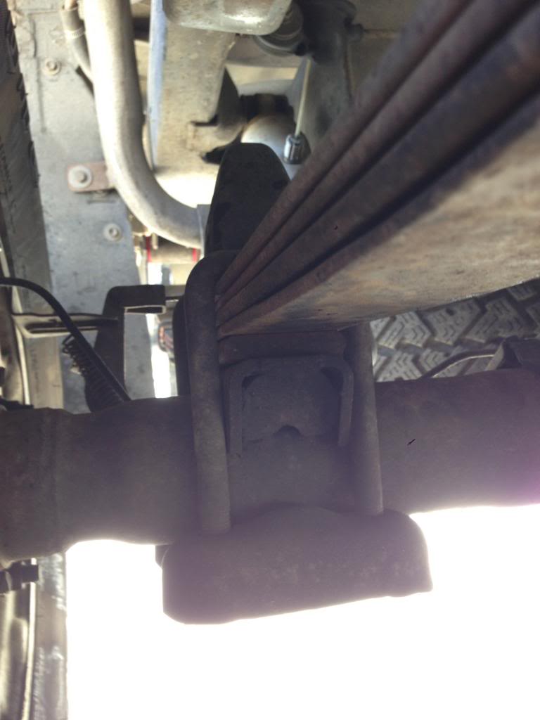
On closer comparison with the diagrams and my own truck, and those pics it looks to me like they may have used 2wd springs installed backwards... a lot of the extra clamps and stops seem to be missing from the ones in the picture... they might not even be toyota springs at all. If there was a picture showing more of the side/top of the spring it would be easier to tell... ie wheel off or shooting the left spring from the right side of the truck so we can see the full profile.
04-01-2013, 10:05 PM
#46
Registered User
Join Date: Feb 2011
Location: Hammond, LA
Posts: 384
Likes: 0
Received 0 Likes
on
0 Posts
well with your diagram, it shows that if you were to reverse the springs, it would offset the axle towards the rear. which makes a whole lot sense. since the rear axle is sitting farther back than it should be. if the springs were spun around 180*...the axle should sit more forward on the springs. thus making it more centered in the wheel well.
the axle is sitting farther back.....which is also creating more drive shaft extension as well. yep you dudes are right. glad its figured out cause it was driving me nuts that i couldnt figure out why you were saying the springs were backwards
the axle is sitting farther back.....which is also creating more drive shaft extension as well. yep you dudes are right. glad its figured out cause it was driving me nuts that i couldnt figure out why you were saying the springs were backwards
04-01-2013, 11:26 PM
#47
Glad you found it. Just to clarify we've been talking about the end of spring #2, not the "clip" parts in the diagram. The clips are multi function, the one on the overload keeps them aligned(not that the U-bolts don't..) and the others make the springs function as a unit during extension. The front end bend keep them from twisting, and reinforce the eyelet. The rear bend transmits the load onto the shackle pin instead of into the top spring(Eg. my "light duty" springs are flat and shorter than the top spring similar to the rear of the #2 spring in the diagram).
It should be mentioned above I think. But..
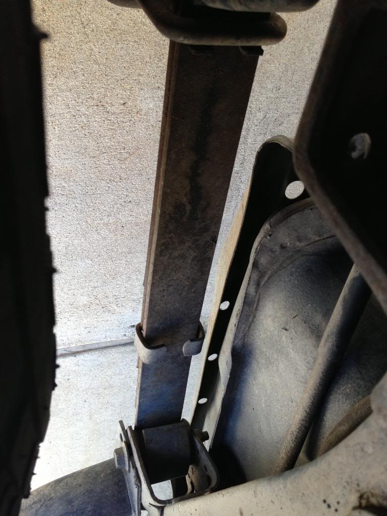
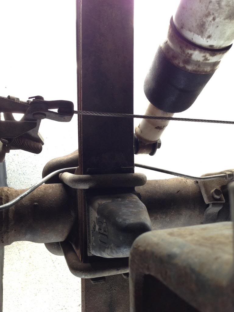
The locator "stuff" is more forward than the center line of the springs. This reduces the available amount of movement fore/aft of the axle assembly when used with the fixed forward mount.
My current thinking on the springs is they were sent out to be rearched, notice the bright shiney new rivet or whatever that is, and maybe they sent the wrong ones back to the install mechanic.
The 93 FSM has these dimensions between spring hangers, G-I
1250 (49.21) 2wd swb, 2wd 0.5 ton lwb, 2wd Xtra cab, 4wd swb, 4wd lwb, 4wd Xtra cab,
1151 (45.31) 2wd 1 ton lwb, 2wd Reg cab slwb
The 88 FSM. All 1151 (45.31)
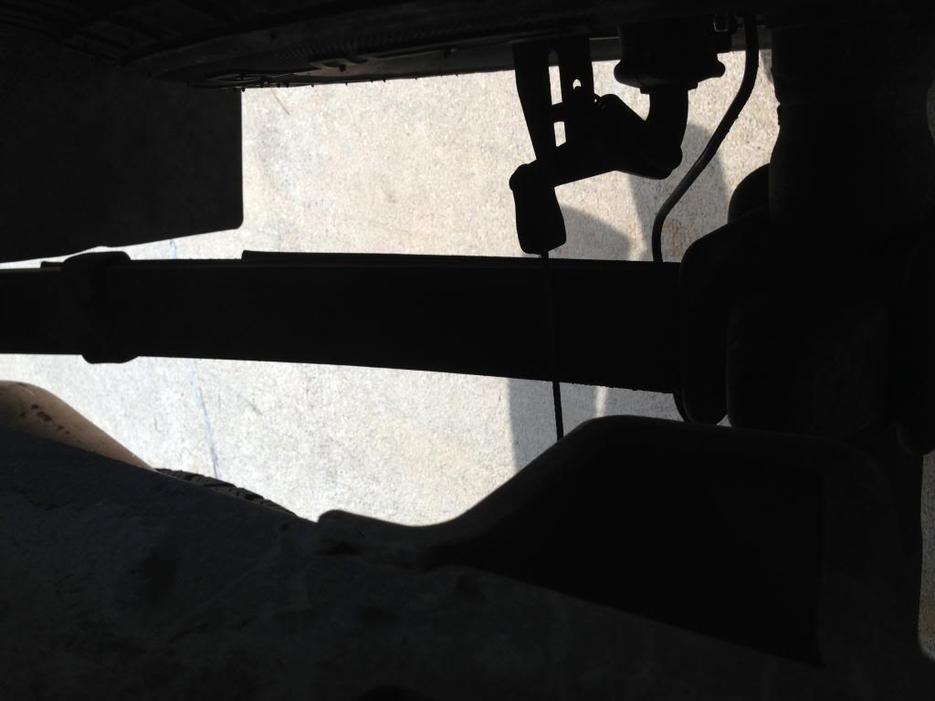
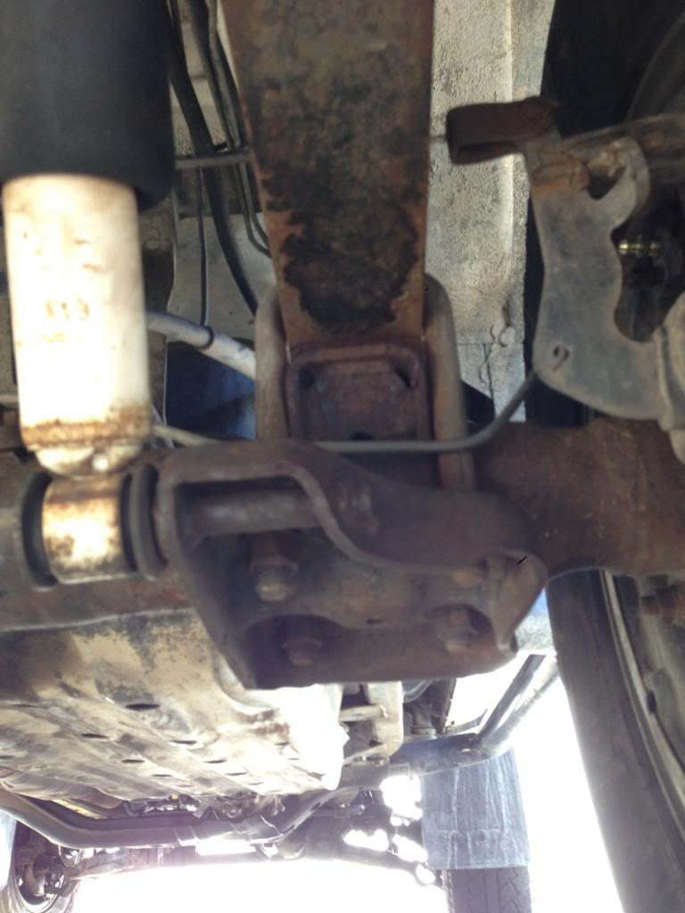
More brain twisters.. How are the axles looking so far off but then there are the bump stops that look like this.
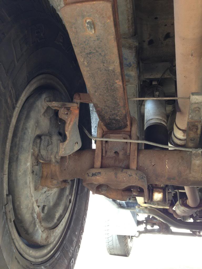
And why did no one mention the gas tank fill tube hiding in the rear of the wheel well

It should be mentioned above I think. But..
The locator "stuff" is more forward than the center line of the springs. This reduces the available amount of movement fore/aft of the axle assembly when used with the fixed forward mount.
My current thinking on the springs is they were sent out to be rearched, notice the bright shiney new rivet or whatever that is, and maybe they sent the wrong ones back to the install mechanic.
The 93 FSM has these dimensions between spring hangers, G-I
1250 (49.21) 2wd swb, 2wd 0.5 ton lwb, 2wd Xtra cab, 4wd swb, 4wd lwb, 4wd Xtra cab,
1151 (45.31) 2wd 1 ton lwb, 2wd Reg cab slwb
The 88 FSM. All 1151 (45.31)
More brain twisters.. How are the axles looking so far off but then there are the bump stops that look like this.
And why did no one mention the gas tank fill tube hiding in the rear of the wheel well
04-02-2013, 06:43 AM
#48
Registered User
Good eye CO_94,
My eyes are not as good as they used to be, but I could also swear that the fill tube doesn't even look connected.
It probably is it just doesn't look like it.
Seems like this rig has a lot of booby traps.
My eyes are not as good as they used to be, but I could also swear that the fill tube doesn't even look connected.
It probably is it just doesn't look like it.
Seems like this rig has a lot of booby traps.
04-02-2013, 09:31 AM
#50
Registered User
Thread Starter
Join Date: Feb 2010
Posts: 103
Likes: 0
Received 0 Likes
on
0 Posts
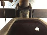
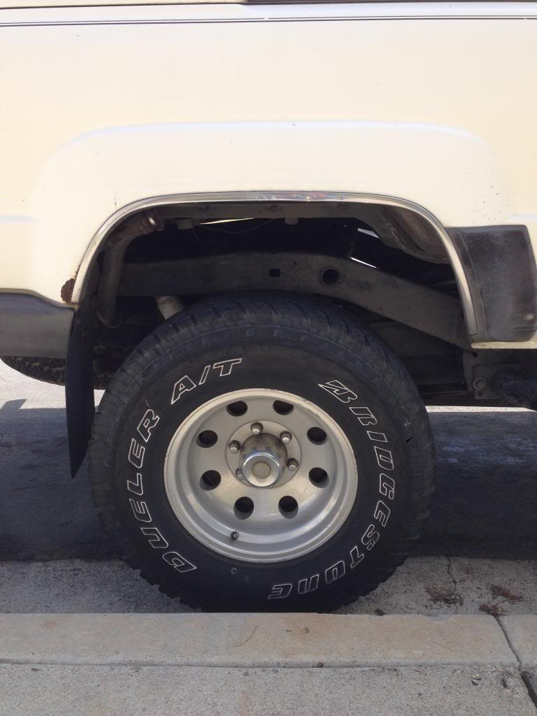
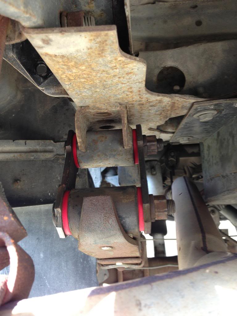
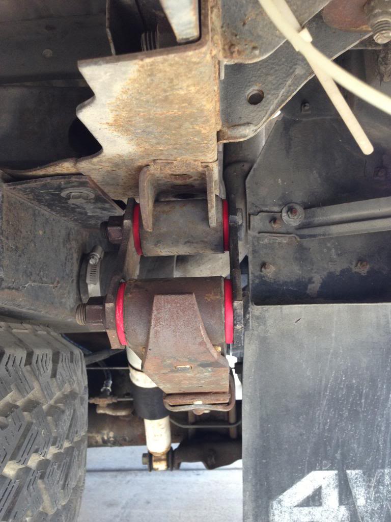
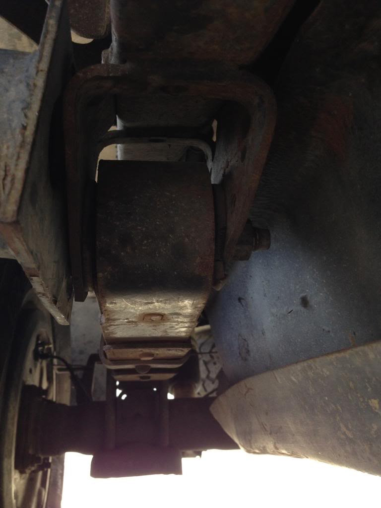
Fill tube? You mean for the extra gas tank? It is connected to the tank, but the connecter is old and needs replacing, that's not from the shop. I did a closer inspection today and more pics. The rear appears correct, I have 4 springs like 4wd should have and the wrap around part is in front. I don't even think they removed the springs completely. I found that they didn't replace the front bushings even though I supplied them. I also measured distance from front spring bolt to middle of axle and it is supposed to be 20.67 and I got just a hair over 21. Also the u bolts for the axle mounts are slightly different thread lengths, and they are all supposed to be equal length. So the rear appears slightly out of alignment, but not horribly so. I also did video of the front, and you can see pitman arm hit inner body bumper. I don't know if that's cuz the aftermarket arms I got were different shape or steering box is off a thread. I'm still looking around for a quality alignment shop. Part of the problem with shops in the area where I live is reliability. I'm in North san diego, and there are quality shops that I could drive to but they are some distance away, and they charge more, and sometimes they don't let you supply your own parts. I actually know a few shop owners and they work good for certain things but all around high quality shops are few and far between locally. It's hard to weed out the monkeys from the mechanics sometimes.

04-02-2013, 10:23 AM
#51
Registered User
San Diego!, I thought you were possibly from another country, hence the dingo in the avatar lol.
Before you take it somewhere else I would at least return to the crime scene and show them the erector set they assembled and demand! (not ask) for some of your hard earned money back.
I'd call this repair a FUBAR in the making.
Maybe if you get some money back, buy some shocks for the rear, IMHO unless your hauling loads all the time those air shocks serve no purpose.
Good luck, hope you get this resolved.
Keep posting updates.
Last edited by ksti; 04-02-2013 at 10:24 AM.
04-02-2013, 03:13 PM
#52
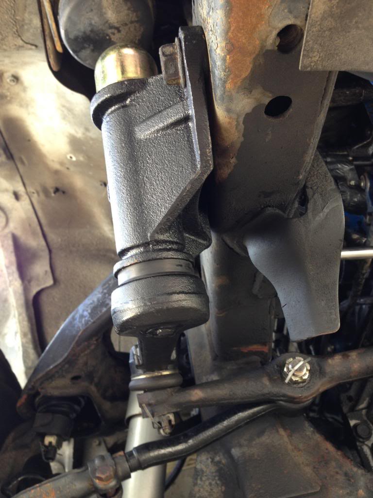
Aren't there three holes in the axel spring mount, perhaps they got shifted to the forward one.
I don't have photo shop installed to do some rough measuring. I'd say it's about 1-2" off center which sounds about right for those mount holes to of been shifted. That would also account for the Bump stop shifted to the front and the U-bolt length difference. Both of those attribute to it kicking the axel rearward.
The next issue (I'll tackle) the steering offset. The steering/alignment shop should be able to sort this but you can DIY.
Going to just by pass all the measuring and math, 'cause I don't wanna explain trig'.
Basicly what I think is going on is the drag bar is shifted to the passenger side.
Mark location of the split in the coupler on each side. Jack up the front end and adjust them. For every one turn lengthening on the right side you need one turn to shorten the left side. Try to get these as close to centered on the marks you made, it'll effect the toe setting if your off. Keep close track of how many turns! If you have to get an assistent cool, if not scratch thru mud and make tick marks on the frame or take a pad and pen with you.
Once you have the threads evened out it should turn an equal sized circle in either direction. My "Old man memory" says the right hand turns are supposed to be slightly tighter than left hand, just cause that is how the roads are designed, but centered is much better than "Holy crap I can't make a left handed U-turn on a 6 lane street!".
And the last problem is the mushy brakes.
Assuming the lines aren't damaged, all the air is out of the lines, the brakes are adjusted. You'll need to tweak the LSPV, don't muck with that untill you get the axle recentered unless you feel it's unsafe to drive or you'll just have to put it back after.
Also make sure the rear brakes are adjusted. I assume these are drum style. Pull the parking brake to full extension, put the vehicle in reverse and proceed to back up 30-50ft and step hard and fast on the brake pedal. Release the parking brake pull forward and repeat untill the vehicle won't go backwards with just the parking brake. If this has no effect after a few times they are way out of adjustment and you're going to have to crawl under and spin the adjustment with a couple screw drivers, but hopefully they got them atleast close and just didn't do the "proceedure".
04-02-2013, 06:27 PM
#53
Registered User
Thread Starter
Join Date: Feb 2010
Posts: 103
Likes: 0
Received 0 Likes
on
0 Posts
So I have an update. Found a quality alignment shop that I plan to take it to soon and I will let them deal with getting the steering and alignment issue sorted. I also took it to the original shop and they are working with me to try to fix the brake issue, we spent two hours on it today. So while the brakes were being bled and pedal was being pushed down it popped. After that it popped again a couple times and seemed to lock up until pedal was released then would be fine. The rod by the pedal was adjusted to see if that made a difference but didn't Brakes were bled at corners and bmc so like 7 points total, and rear brakes were tightened. So now parking brake works, but brake pedal is still mushy. Brakes seems to grab fine they just don't engage until pedal is over halfway and then pedal goes down far and doesn't feel real firm. Absolutely everything has been replaced except booster, and there are no leaks. So by ruling everything out it seems like the booster must be the issue. Possibly a small leak so that it pushes the air out when pedal is pushed. When you push on brake pedal a bunch at once while truck is running it also makes it want to stall out, so that seems indicative of a vacuum leak too possibly. Any other suggestions?
04-02-2013, 06:59 PM
#54
04-02-2013, 09:38 PM
#55
Registered User
Join Date: Sep 2011
Location: Citrus Heights CA
Posts: 200
Likes: 0
Received 0 Likes
on
0 Posts
I am sorry for not looking up the hours, I keep forgetting (a terrible excuse)...
But the pushrod clearance might be wrong if they replaced the master cylinder. If there is too little clearance the brake pedal will have to travel farther to engage the brakes, which might cause your problem. If the booster is leaky your brakes won't have power assist, so you won't get a mushy pedal.
my 2 cents
04-03-2013, 02:12 PM
#56
Registered User
Thread Starter
Join Date: Feb 2010
Posts: 103
Likes: 0
Received 0 Likes
on
0 Posts
After that initial pop the pedal pushrod was adjusted a few times, but to no effect. I know that a bad booster should make pedal hard but what else could it be? By process of elimination it seems to be the only variable left right? I know for a fact that the bmc was leaking into the booster for years. I can get one for $200 and the shop will install it. I don't like just throwing parts at vehicles but it's the only part that can be thrown. I'll double check the pedal specs provided by Co, but I don't know what else to do.
04-03-2013, 02:18 PM
#57
Registered User
Thread Starter
Join Date: Feb 2010
Posts: 103
Likes: 0
Received 0 Likes
on
0 Posts
These are the vids of the turning radius issue in front. You can see the driver side pitman arm hot the inner body bumper, makes me think it's off a tooth. They are aftermarket arms.
http://s208.photobucket.com/user/Cge...64146.mp4.html
http://s208.photobucket.com/user/Cge...a5d82.mp4.html
http://s208.photobucket.com/user/Cge...64146.mp4.html
http://s208.photobucket.com/user/Cge...a5d82.mp4.html
04-03-2013, 04:23 PM
#58
Registered User

Join Date: Feb 2011
Location: New Hampshire
Posts: 124
Likes: 0
Received 0 Likes
on
0 Posts
Did they replace the rotors? Either way, one or both rotors could be worped causing the pistons to be pushed back and you having to make up the distance, giving you the mushy feel, but fine after you pump it or reach half way...
I just redid my 4 corners, drums, rotors, pads, shoes, and calipers. One of my drums was out of round. Can happen to rotors to. Have them check the runout on the rotors.
Good luck!
I just redid my 4 corners, drums, rotors, pads, shoes, and calipers. One of my drums was out of round. Can happen to rotors to. Have them check the runout on the rotors.
Good luck!
04-03-2013, 04:57 PM
#59
After that initial pop the pedal pushrod was adjusted a few times, but to no effect. I know that a bad booster should make pedal hard but what else could it be? By process of elimination it seems to be the only variable left right? I know for a fact that the bmc was leaking into the booster for years. I can get one for $200 and the shop will install it. I don't like just throwing parts at vehicles but it's the only part that can be thrown. I'll double check the pedal specs provided by Co, but I don't know what else to do.
Here are the inspection directions from that manual link.
1. OPERATING CHECK
(a) Depress the brake pedal several times with the engine off, and check that there is no change in the pedal reserve distance.
(b) Depress the brake pedal and start engine. If the pedal goes down slightly, operation is normal.
2. AIR TIGHTNESS CHECK
(a) Start the engine and stop it after one or two minutes. Depress the brake pedal several times slowly. If the pedal goes down deepest the first time, but gradually rises after the second or third time, the booster is air tight.
(b) Depress the brake pedal while the engine is running, and stop it with the pedal depressed . If there is no change in pedal reserve travel after holding� the pedal for thirty seconds, the booster is air tight.
You'll still get a mushy pedal w/o the booster, IMO. Just due to the mechanical advantage it should be enough to compress air. If it wasn't enough to compress air/fluid I'd be undrivable w/o the power assist.
Originally Posted by http://personal.utulsa.edu/~nathan-buchanan/93fsm/steering/16steer0.pdf
5. CONNECT TIE ROD
(a) Screw the tie rod ends into the tie rod.
HINT: The tie rod length should be approximately 328.5mm (12.933 in.), and the remaining length of threads on both tie rod ends should be equal
(a) Screw the tie rod ends into the tie rod.
HINT: The tie rod length should be approximately 328.5mm (12.933 in.), and the remaining length of threads on both tie rod ends should be equal
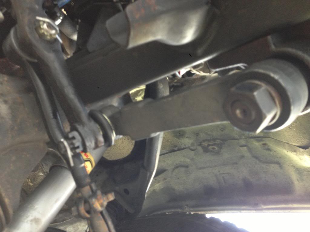
It should be contacting the bump stops on the wheel not the steering stops on the frame. Have them correct/adjust the tie rods like I mentioned before.
Might not be a bad idea to get the rubber on the bump stops, can't tell for sure in the videos if it's there and intact. They have a minor effect onthe travel distance.
You can see the locations of the fwd stops in your video but Here is a thread that shows a good clear picture. Once the tie rods are corrected and the relay rod centered you should have proper factory turn radius.
04-11-2013, 09:07 AM
#60
Registered User
Thread Starter
Join Date: Feb 2010
Posts: 103
Likes: 0
Received 0 Likes
on
0 Posts
Latest Update: Got a rebuilt cardone booster and got that installed. Now the whole brake system has been replaced, the only thing original is the hard lines. Pedal feel is much improved and brakes work good and I can lock them up if needed but the only thing is the pedal engages a bit low imo, should engage within first inch. Parking brake works too. I'm gonna use the fsm to check on adjustments and such. It looks like the booster actuator rod that goes to bmc can not be adjusted and the backside rod that goes to the pedal is adjusted in as far as possible.
On a side note, as soon as I got it home I noticed a trail of fluid up the driveway. Turns out my steering box was leaking from the top middle nut it was way loose. Tightened it up and leak went away. I think this was from the retard alignment shop that initially did the truck they probably didn't tighten it good and it worked loose. Is there a specific torque to that one? I found a real good alignment shop that should be able to take care of the suspension issue, so gonna get it there in next day or two. Meanwhile, the day after the truck sprung a leak my car decided to have a coolant hose go, and they were conveniently located under the intake manifold. So that's my chore for the day, o the joys of owning older cars.
On a side note, as soon as I got it home I noticed a trail of fluid up the driveway. Turns out my steering box was leaking from the top middle nut it was way loose. Tightened it up and leak went away. I think this was from the retard alignment shop that initially did the truck they probably didn't tighten it good and it worked loose. Is there a specific torque to that one? I found a real good alignment shop that should be able to take care of the suspension issue, so gonna get it there in next day or two. Meanwhile, the day after the truck sprung a leak my car decided to have a coolant hose go, and they were conveniently located under the intake manifold. So that's my chore for the day, o the joys of owning older cars.


