Alternator Wiring
 06-11-2008, 04:06 PM
#1
Registered User
Thread Starter

Join Date: Aug 2006
Location: Foothill Ranch, CA
Posts: 10
Likes: 0
Received 0 Likes
on
0 Posts
Alternator Wiring
I want to rewire my stock 22re alternator in my 1993 2wd pickup and have a couple of questions. Can I wire the stock alternator up with one wire? I want to wire it directly to the starter. My truck is offroad only and I do not use any of the stock accessories.


 06-12-2008, 08:48 AM
#2
I am thinking you do not want to wire directly to the starter...but i may be incorrect?
Many of the Demo Derby guys run one wire GM alternators. As long as there is a lead going from the post to the battery, you are good.
BTW, that truck is sick!
Many of the Demo Derby guys run one wire GM alternators. As long as there is a lead going from the post to the battery, you are good.
BTW, that truck is sick!
06-12-2008, 09:44 AM
#3
Registered User
Join Date: Jun 2008
Location: Small town, CO.
Posts: 180
Likes: 0
Received 0 Likes
on
0 Posts
Nice ride
You could run the larger wire to the starter how ever the other ones must also be used. The alternator is externoly (sp) regulated and with out the other wires there would be nothing telling the alternator to charge or stop charging. I don't remember what wire goes to what but I changed to a gm one wire and had to modify the harness so the battery would charge.
hope that helps.
06-12-2008, 10:24 AM
#5
Contributing Member
Nice truck! This link helped me understand alternator wiring better:
http://www.autoshop101.com/trainmodu...or/alt101.html
It looks like to me the only wire you wouldn't need would be the one for the charge light.
http://www.autoshop101.com/trainmodu...or/alt101.html
It looks like to me the only wire you wouldn't need would be the one for the charge light.
Last edited by mt_goat; 06-12-2008 at 10:30 AM.
06-12-2008, 01:41 PM
#7
Registered User
Thread Starter
Join Date: Aug 2006
Location: Foothill Ranch, CA
Posts: 10
Likes: 0
Received 0 Likes
on
0 Posts
Well what I wanted to do really was just run one wire from the alternator directly to the battery. I guess the stock toyota alternator is not set up to be wired like that. My alternator is not running right now and im sure it has something to do with the stock wiring. I think I will just ditch the stock alternator and go with a beefier GM one wire alternator.
The specs on the truck are:
1993 Toyota 22re 2wd
Custom a-arm's with King 2.5 " Coilover Shocks 13" Travel
62" Long travel deaver leaf springs with King 2.5" shocks 18" Travel
Fully caged front to back with 1.5 DOM
JD Fabrication Upgraded steering with new pitman arm, idle arm and center link
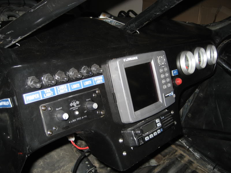
Fiberglass dash, race radio, intercom, parker pumper fresh air system, Lowrance Baja GPS
Autometer Gauges and Tachometer
Beard Ultra Pro seats with Crow 5 point Harnes
33 gallon Bronco fuel tank
33x10.5x15 BFG Baja TA's
Toyota 8" with 5.29's and spool
4 X Hella 500's on the lightbar uptop
2 X Vision X HID Lights on the bumper
Custom aluminum rear led light mount
Craftsman aluminum race jack with custom mount
Optima Yellow Top Battery
Im sure I missed some other stuff but I think that is most of it.
The specs on the truck are:
1993 Toyota 22re 2wd
Custom a-arm's with King 2.5 " Coilover Shocks 13" Travel
62" Long travel deaver leaf springs with King 2.5" shocks 18" Travel
Fully caged front to back with 1.5 DOM
JD Fabrication Upgraded steering with new pitman arm, idle arm and center link
Fiberglass dash, race radio, intercom, parker pumper fresh air system, Lowrance Baja GPS
Autometer Gauges and Tachometer
Beard Ultra Pro seats with Crow 5 point Harnes
33 gallon Bronco fuel tank
33x10.5x15 BFG Baja TA's
Toyota 8" with 5.29's and spool
4 X Hella 500's on the lightbar uptop
2 X Vision X HID Lights on the bumper
Custom aluminum rear led light mount
Craftsman aluminum race jack with custom mount
Optima Yellow Top Battery
Im sure I missed some other stuff but I think that is most of it.
Last edited by bajaguy; 06-12-2008 at 01:47 PM.
Trending Topics
06-12-2008, 02:09 PM
#8
Contributing Member
Doesn't that suck power from the engine by running the alternator in full charging mode all the time? Plus it will be over-charging that yellow top, something a deep cycle battery doesn't like.
06-12-2008, 03:55 PM
#9
Registered User
Thread Starter
Join Date: Aug 2006
Location: Foothill Ranch, CA
Posts: 10
Likes: 0
Received 0 Likes
on
0 Posts
Isnt the internal voltage regulator in the Alternator what keeps the alternator from over charging the battery? Either ways I just ordered a GM one wire alternator from Summit and a mounting bracket so it bolts right on the stock toyota alternator mounts.
06-12-2008, 05:09 PM
#10
Contributing Member
Did you read that link I posted above? The regulator won't work without the wires connected to it.
06-12-2008, 05:52 PM
#11
Registered User
Join Date: Mar 2008
Location: Temecula Valley, CA
Posts: 12,723
Likes: 0
Received 4 Likes
on
4 Posts
you can't easily do a 1 wire installation.
you can make a fairly direct setup to allow the alternator to work. there are 4 connections to the alternator, and the alternator grounds through the housing. there should be 3 connections in one 'plug' and 1 connection through a stud on the alternator.
three connector plug:
-- 1 connection for charging system failure light uses 'differential voltage' to illuminate the light- when the alternator output falls too low or fails, the voltage supplied to the light flows forward through the diode to the alternator and causes the light to illuminate. The diode prevents voltage from the alternator from flowing backwards through the light and lighting it when alternator output is good.
-- 1 connection switched voltage from the ignition switch- energizes the regulator circuit so that when the engine is running the regulator can operate.
-- 1 connection fused from the battery (fused 40A, from constant on voltage)
the stud:
-- alternator output to the battery. (fused 100A or 80A based on alt output, also supplies fused connection above- it has its fuse inline)
All 4 of the connections must be made for the alternator to work.
I recommend going to the battery for the alternator output and not the starter due to resistance losses from the extra length of cable. if your setup has a disconnect on the hot lead to the battery (i've heard of things like this for roll-over or crash protection), then wiring to the starter is acceptable but expect a tenth or so voltage loss and use the largest gauge wire you can, at least 2AWG.
the drawing here shows the basic alternator wiring:
http://www.ncttora.com/fsm/1990-1995...i/charging.pdf
print it out. it has plug diagrams and fuse ratings listed. keep in mind it is a generic drawing that shows the wires for both the 4 and 6 cyl engines on one drawing. ignore the 6 cyl wiring.
06-13-2008, 08:20 AM
#12
Registered User
Thread Starter
Join Date: Aug 2006
Location: Foothill Ranch, CA
Posts: 10
Likes: 0
Received 0 Likes
on
0 Posts
you can't easily do a 1 wire installation.
you can make a fairly direct setup to allow the alternator to work. there are 4 connections to the alternator, and the alternator grounds through the housing. there should be 3 connections in one 'plug' and 1 connection through a stud on the alternator.
three connector plug:
-- 1 connection for charging system failure light uses 'differential voltage' to illuminate the light- when the alternator output falls too low or fails, the voltage supplied to the light flows forward through the diode to the alternator and causes the light to illuminate. The diode prevents voltage from the alternator from flowing backwards through the light and lighting it when alternator output is good.
-- 1 connection switched voltage from the ignition switch- energizes the regulator circuit so that when the engine is running the regulator can operate.
-- 1 connection fused from the battery (fused 40A, from constant on voltage)
the stud:
-- alternator output to the battery. (fused 100A or 80A based on alt output, also supplies fused connection above- it has its fuse inline)
All 4 of the connections must be made for the alternator to work.
I recommend going to the battery for the alternator output and not the starter due to resistance losses from the extra length of cable. if your setup has a disconnect on the hot lead to the battery (i've heard of things like this for roll-over or crash protection), then wiring to the starter is acceptable but expect a tenth or so voltage loss and use the largest gauge wire you can, at least 2AWG.
the drawing here shows the basic alternator wiring:
http://www.ncttora.com/fsm/1990-1995...i/charging.pdf
print it out. it has plug diagrams and fuse ratings listed. keep in mind it is a generic drawing that shows the wires for both the 4 and 6 cyl engines on one drawing. ignore the 6 cyl wiring.
you can make a fairly direct setup to allow the alternator to work. there are 4 connections to the alternator, and the alternator grounds through the housing. there should be 3 connections in one 'plug' and 1 connection through a stud on the alternator.
three connector plug:
-- 1 connection for charging system failure light uses 'differential voltage' to illuminate the light- when the alternator output falls too low or fails, the voltage supplied to the light flows forward through the diode to the alternator and causes the light to illuminate. The diode prevents voltage from the alternator from flowing backwards through the light and lighting it when alternator output is good.
-- 1 connection switched voltage from the ignition switch- energizes the regulator circuit so that when the engine is running the regulator can operate.
-- 1 connection fused from the battery (fused 40A, from constant on voltage)
the stud:
-- alternator output to the battery. (fused 100A or 80A based on alt output, also supplies fused connection above- it has its fuse inline)
All 4 of the connections must be made for the alternator to work.
I recommend going to the battery for the alternator output and not the starter due to resistance losses from the extra length of cable. if your setup has a disconnect on the hot lead to the battery (i've heard of things like this for roll-over or crash protection), then wiring to the starter is acceptable but expect a tenth or so voltage loss and use the largest gauge wire you can, at least 2AWG.
the drawing here shows the basic alternator wiring:
http://www.ncttora.com/fsm/1990-1995...i/charging.pdf
print it out. it has plug diagrams and fuse ratings listed. keep in mind it is a generic drawing that shows the wires for both the 4 and 6 cyl engines on one drawing. ignore the 6 cyl wiring.
08-25-2012, 07:36 PM
#17
Registered User

Join Date: Jan 2012
Location: Yuma, Arizona
Posts: 14
Likes: 0
Received 0 Likes
on
0 Posts
Anyone know why my alternator isnt. Harging my battery? Every single fuse is good but I check the connections where the fuse goes with a test light but its not receiving power on the bridge. This happened overnight, I woke up and found this out when I checked the volt meter. By the way its a brand new alternator
05-15-2017, 05:10 PM
#18
Registered User

Join Date: May 2017
Posts: 11
Likes: 0
Received 0 Likes
on
0 Posts
Link to summit website please
05-15-2017, 05:33 PM
#19

Thread
Thread Starter
Forum
Replies
Last Post


