3vze diagnostic port terminal diagram?
 05-30-2012, 01:24 PM
#1
Registered User
Thread Starter
Join Date: Aug 2007
Location: Atco nj
Posts: 14
Likes: 0
Received 0 Likes
on
0 Posts
3vze diagnostic port terminal diagram?
I've been searching the forum and was trying to find a diagram of that each terminal is for on the diagnostic port in the engine bay?
I know the fuel pump ecu code but would like to know what the rest do.
Like can Check the o2 with a air fuel guage at that port?
If anyone knows please share.
I know the fuel pump ecu code but would like to know what the rest do.
Like can Check the o2 with a air fuel guage at that port?
If anyone knows please share.
 05-30-2012, 03:41 PM
#2
Registered User
Join Date: Apr 2011
Location: West Palm Beach, FL
Posts: 487
Likes: 0
Received 0 Likes
on
0 Posts
Check the FSM under electrical, and then under MFI. I can not link the page for you because you did not mention which one of the trucks you were working on.
FSM link in my signature.
Sorry, did not see the 3vze in title.
FSM link in my signature.
Sorry, did not see the 3vze in title.
Last edited by 93toyrunner2; 05-30-2012 at 03:47 PM. Reason: sorry
05-30-2012, 03:43 PM
#3
Anywho...from my 88 3VZ-E...
FP = Fuel Pump
E1 = Engine ground
Ox = Oxygen Sensor
Cco = Catalytic convertor
T = ECU diagnostic Test mode request terminal
E2 = Sensor ground
+B = Battery positive(12V)
VF = Voltage Feedback(see pages 2,13,14 of this pdf)
TEM = A/T oil TEMperature warning computer???
ECT = Electronically Controlled Transmission computer
IG- = Ignitor negative(tachometer signal)
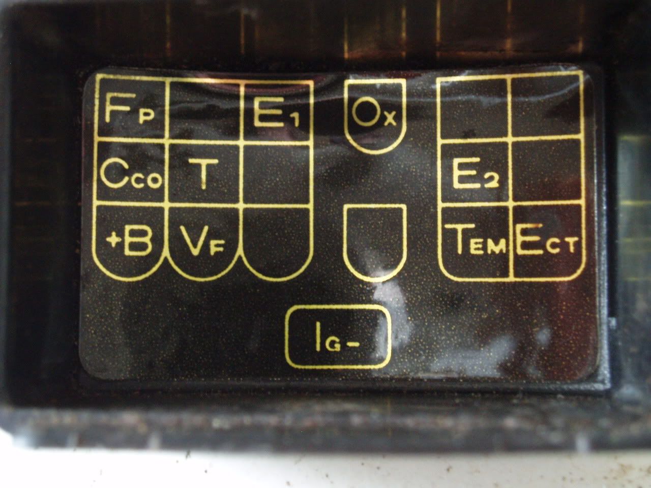
And...no..you can't. But if you want to know what they're supposed to be used for...read the 88 FSM.
FP = Fuel Pump
E1 = Engine ground
Ox = Oxygen Sensor
Cco = Catalytic convertor
T = ECU diagnostic Test mode request terminal
E2 = Sensor ground
+B = Battery positive(12V)
VF = Voltage Feedback(see pages 2,13,14 of this pdf)
TEM = A/T oil TEMperature warning computer???
ECT = Electronically Controlled Transmission computer
IG- = Ignitor negative(tachometer signal)
And...no..you can't. But if you want to know what they're supposed to be used for...read the 88 FSM.
Last edited by MudHippy; 05-31-2012 at 01:15 PM.
05-31-2012, 07:49 AM
#5
Registered User

Join Date: Sep 2007
Location: San Francisco East Bay
Posts: 8,252
Likes: 0
Received 820 Likes
on
648 Posts
O2 gauge? The only one I've ever heard of is a pressure gauge, and I'm sure you're talking about something else.
You can put a voltmeter on the Ox pin to measure the output of the sensor. It should flop between about 0.4 and 0.9 volts, and flop back and forth about 8 times in 10 seconds. This is easy to see on an old-fashioned needle meter, but you need one that will read about 1.5v full scale. With a digital meter the scale is easy, but the update rate may not be fast enough to see the change. So you need a digital meter with an "analog" bar graph.
You can put a voltmeter on the Ox pin to measure the output of the sensor. It should flop between about 0.4 and 0.9 volts, and flop back and forth about 8 times in 10 seconds. This is easy to see on an old-fashioned needle meter, but you need one that will read about 1.5v full scale. With a digital meter the scale is easy, but the update rate may not be fast enough to see the change. So you need a digital meter with an "analog" bar graph.
05-31-2012, 08:51 AM
#6
You're supposed to use the VF/VF1 terminal to check the output voltage of the O2 sensor. According to the FSM.
I can't find any references in the FSM(or anywhere else) as to exactly what the Ox/Ox1 terminal is supposed to be used for. Though I won't argue that it can't be used to check the output voltage of the O2 sensor too. Because it can.
So...what's the difference between checking the voltage through the Ox/Ox1 or VF/VF1 terminals?
If you check the voltage via the Ox/Ox1 terminal, that's the voltage signal coming directly from the O2 sensor(before it's received by the ECU).
If you check the voltage via the VF/VF1 terminal, w/ the T/TE1 terminal also ON, that gives you an emulated O2 sensor voltage signal after it's been processed by the ECU. Or, when checking the voltage w/ the T/TE1 terminal OFF, the VF/VF1 voltage then represents the learned value correction.
Specified voltage at Ox/Ox1 only confirms if the sensor is functioning.
Specified voltage at VF/VF1 also confirms that, and that the ECU is functioning too.
Last edited by MudHippy; 06-02-2012 at 10:07 AM.
05-31-2012, 10:22 AM
#7
Registered User
Join Date: Aug 2010
Location: Oregon, USA
Posts: 2,027
Likes: 0
Received 0 Likes
on
0 Posts
I've always thought about using an Arduino to set up something similar to the old Toyota diagnostic tools / dataloggers. I just wish I had the time to program it.
Trending Topics
06-01-2012, 02:28 PM
#8
Registered User

Join Date: May 2012
Location: 91765
Posts: 591
Likes: 0
Received 0 Likes
on
0 Posts
Ive had O2 (air/fuel) gauges hooked up to the Ox/Ox1 for years, But as I mentioned above dont use a ohm meter on that port.
I do not remember the spacifics of the Vf ports.
I do not remember the spacifics of the Vf ports.

Thread
Thread Starter
Forum
Replies
Last Post
runnermedic
95.5-2004 Tacomas & 96-2002 4Runners
13
09-21-2015 05:20 PM
EatChipsNow
86-95 Trucks & 4Runners
8
09-09-2015 01:25 AM
kelly1450
95.5-2004 Tacomas & 96-2002 4Runners
1
09-02-2015 12:29 PM


