
22R Rebuild
 10-05-2009, 05:13 PM
#21
Registered User
Thread Starter

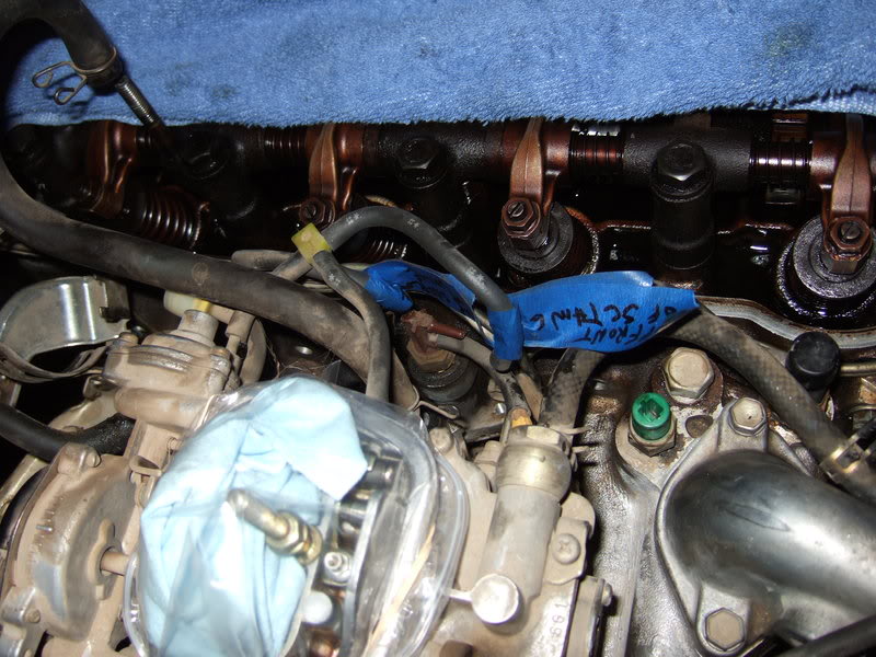
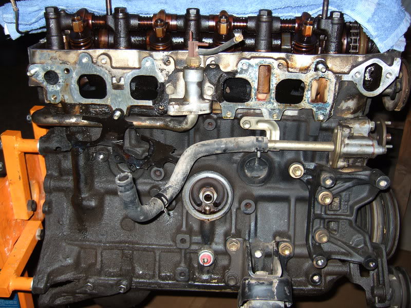
Here are a few pics, starting with an angled shot from the rear of the intake.
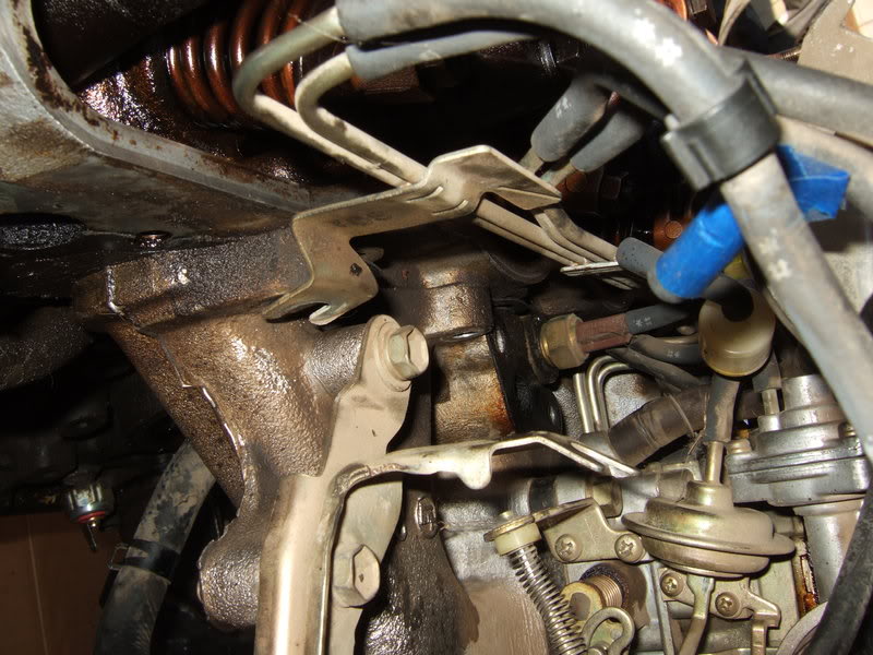
Moving along the top. For perspective, you can see where the EGR tube connects in both pics. That vacuum tubing assembly will stay on the intake. It's free from the head.
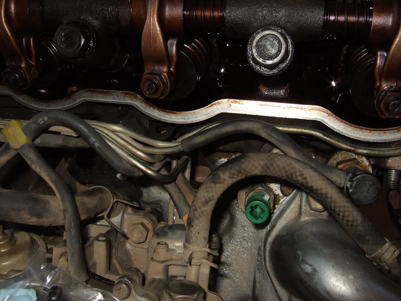
Up front.
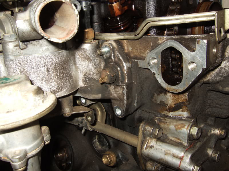
Underneath.
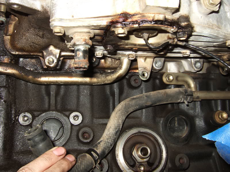
Can you see anything I'm missing? The coolant pipe that runs to the bottom of the side cover is also stuck tight. It doesn't need to come off to pull the intake, but may indicate how baked on some things are.
I doubt it will help, but I sprayed PB Blaster all around the intake gasket.
Moving along the top. For perspective, you can see where the EGR tube connects in both pics. That vacuum tubing assembly will stay on the intake. It's free from the head.
Up front.
Underneath.
Can you see anything I'm missing? The coolant pipe that runs to the bottom of the side cover is also stuck tight. It doesn't need to come off to pull the intake, but may indicate how baked on some things are.
I doubt it will help, but I sprayed PB Blaster all around the intake gasket.
 10-05-2009, 07:09 PM
#22
Registered User
Thread Starter
I got the intake off.
After some contemplation (and a few beers), I went after it with a 2x4, a 1x2, and a hammer. After smacking pretty hard around the edges it eventually came free.
I had to disconnect the 2 hoses going to the valve in the side cover:
The intake as I removed it.
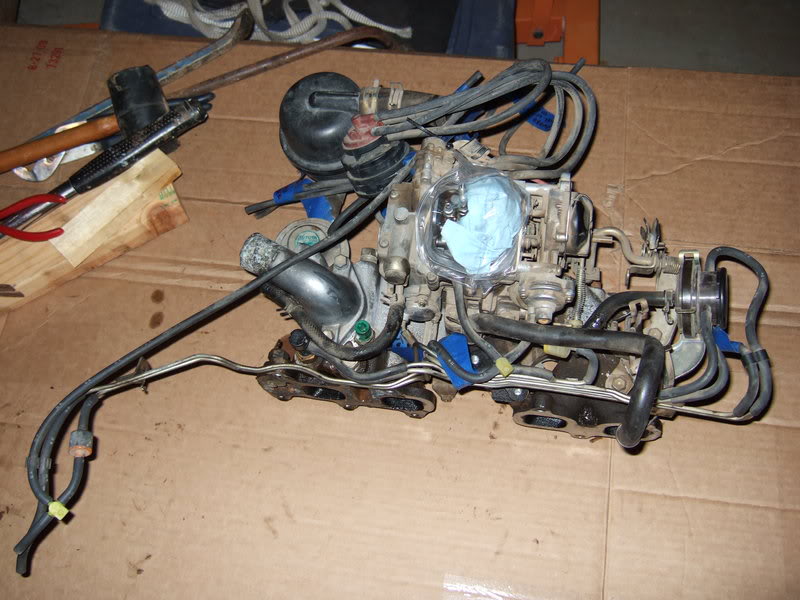
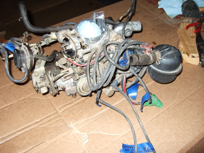
Note the pencil end stuck in the vacuum line that goes to the AAP. Mine ruptured years ago, and the engine wouldn't idle when cold. I cut the line and plugged both ends. Problem solved.
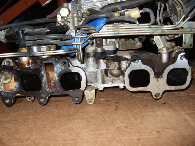
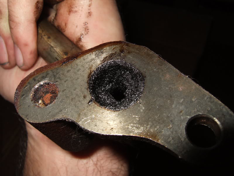
EGR tube.
After some contemplation (and a few beers), I went after it with a 2x4, a 1x2, and a hammer. After smacking pretty hard around the edges it eventually came free.
I had to disconnect the 2 hoses going to the valve in the side cover:
The intake as I removed it.
Note the pencil end stuck in the vacuum line that goes to the AAP. Mine ruptured years ago, and the engine wouldn't idle when cold. I cut the line and plugged both ends. Problem solved.
EGR tube.
Last edited by flyingbrass; 10-05-2009 at 08:46 PM.
10-05-2009, 10:50 PM
#23
Registered User
Thread Starter
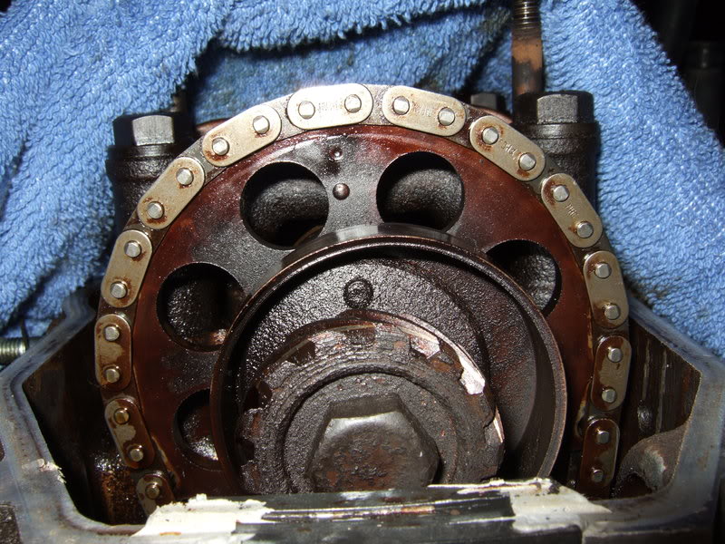
I turned the engine to TDC before removing the distributor. Replacement chains have an identifiable link to put on the dot. All the links on my factory chain are the same color. Ignore the effect from the camera's flash. Two at the top say Japan -- the one over the dot and the one to the right of it. I don't know if that is significant because I didn't pay attention to the rest of the chain. There may be other adjoining links that say Japan. Doesn't really matter except for forensics because I'll be installing a new timing set.
While at TDC I shook the loose rocker arms to estimate the valve clearances. #3 exhaust caused a holy $&@! moment, so I checked them all.
1 intake: .006
1 exhaust: .008
2 intake: .001-.002
2 exhaust: .008
3 intake: .007
3 exhaust: WAY off. To estimate how much, I worked in the the .035 and .032 feelers stacked together, but barely, so I figure maybe .065-.066 actual. Ouch.
4 intake: .007
4 exhaust: .010
All clearances were fine last I checked. Can't remember if they were .007 and .011 or .008 and .012, but all were about right. Something got screwed, but what, why and how?
I plan to use new rocker adjusting screws and maybe also new nuts. I've read that these are not items to skimp on, so I'll probably buy them from Toyota.
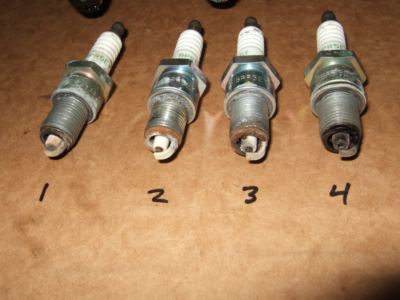
I pulled the plugs. I had to use a cheater pipe to wrench out #2 and #3. I knew these were messed up before, and I plan to use a new head, but fighting plugs out still made me queasy.
While at TDC I shook the loose rocker arms to estimate the valve clearances. #3 exhaust caused a holy $&@! moment, so I checked them all.
1 intake: .006
1 exhaust: .008
2 intake: .001-.002
2 exhaust: .008
3 intake: .007
3 exhaust: WAY off. To estimate how much, I worked in the the .035 and .032 feelers stacked together, but barely, so I figure maybe .065-.066 actual. Ouch.
4 intake: .007
4 exhaust: .010
All clearances were fine last I checked. Can't remember if they were .007 and .011 or .008 and .012, but all were about right. Something got screwed, but what, why and how?
I plan to use new rocker adjusting screws and maybe also new nuts. I've read that these are not items to skimp on, so I'll probably buy them from Toyota.
I pulled the plugs. I had to use a cheater pipe to wrench out #2 and #3. I knew these were messed up before, and I plan to use a new head, but fighting plugs out still made me queasy.
Last edited by flyingbrass; 10-06-2009 at 01:26 AM.
10-06-2009, 06:13 PM
#24
Registered User
Thread Starter
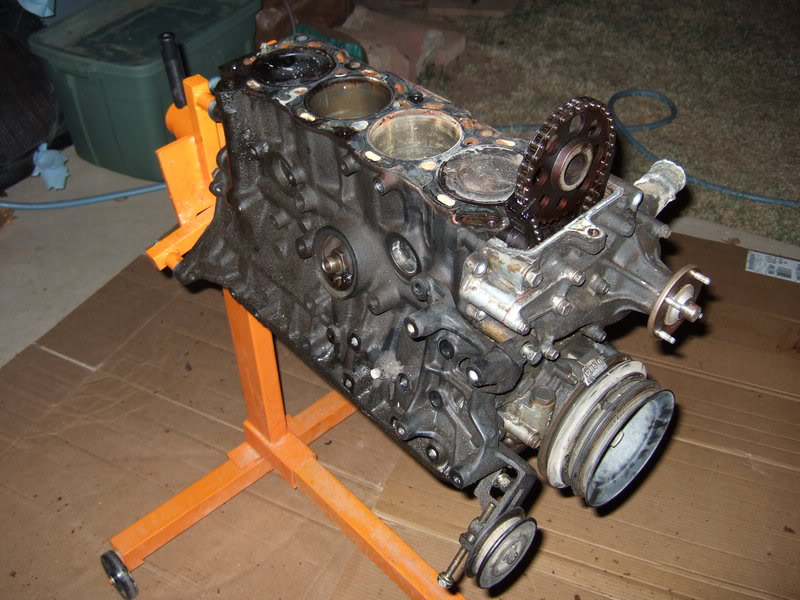
Today's progress.
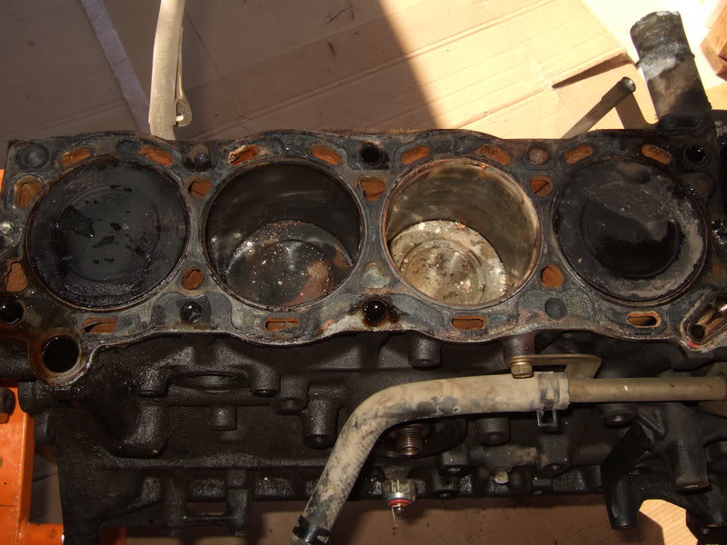
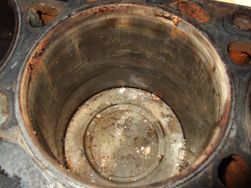
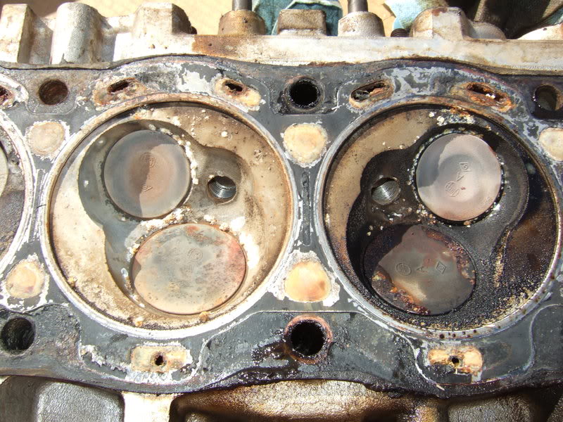
Number 2.
Number 3.
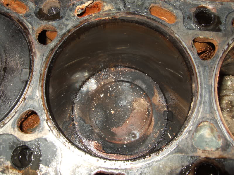
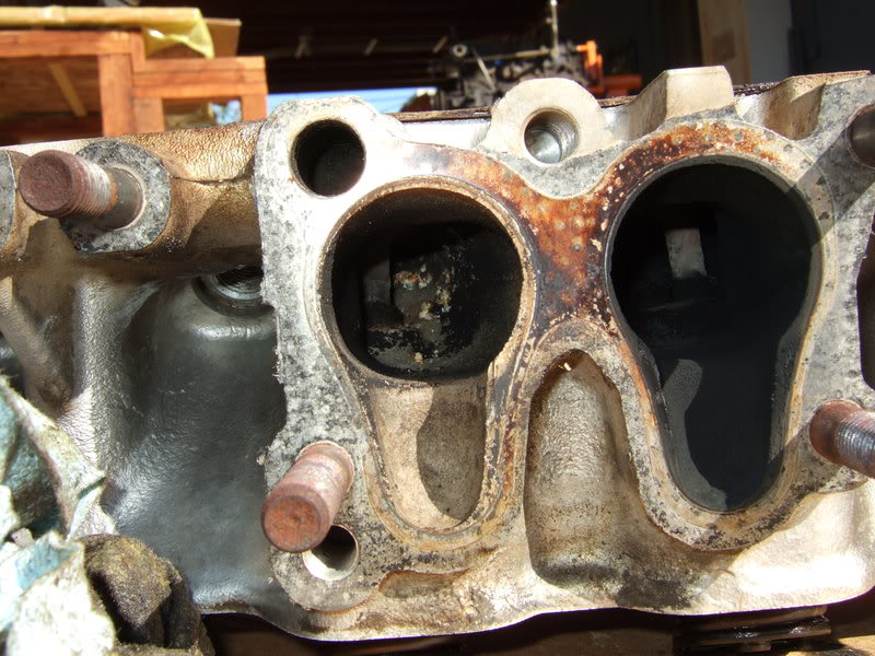
Gotta like this one. #3 exhaust valve is stuck. You can see daylight around it. That had to have happened very recently.
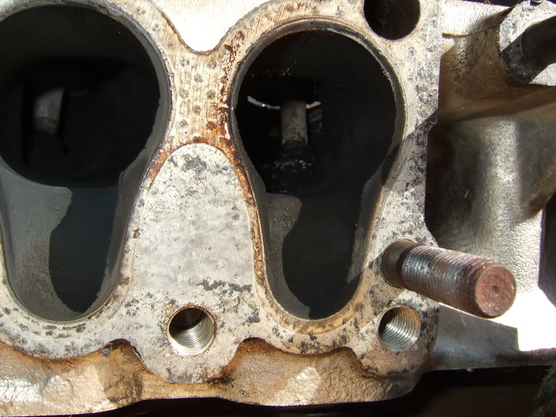
#2 and #3.
Number 2.
Number 3.
Gotta like this one. #3 exhaust valve is stuck. You can see daylight around it. That had to have happened very recently.
#2 and #3.
10-06-2009, 09:15 PM
#27
Registered User
Thread Starter
I hope it ends up being a love story. Right now it's a more of a suspense. I look at the growing accumulation of parts and wonder if I'll be able to put this thing back together correctly. I hope I don't make an expensive stupid mistake along the way.
Last edited by flyingbrass; 10-06-2009 at 09:16 PM.
10-06-2009, 10:00 PM
#28
Registered User
Thread Starter
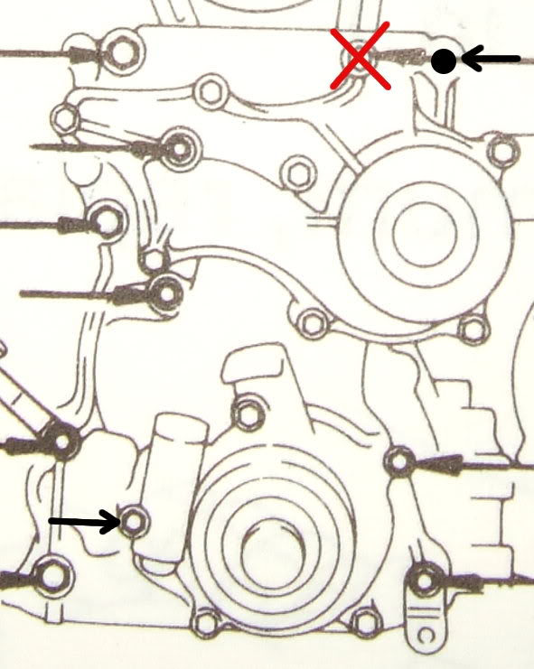
I took a picture of the diagram in my FSM showing the timing cover bolts, blew it up a bit, printed it out, and taped it to some cardboard. I'll poke the bolts through in the proper places as I take them out. A bolt also comes in from the rear.
If anyone wants it, here you go. Right click and "save as."
Edit: the diagram showed an incorrect bolt and didn't have an arrow pointing at another. Here's the fixed version.
If anyone wants it, here you go. Right click and "save as."
Edit: the diagram showed an incorrect bolt and didn't have an arrow pointing at another. Here's the fixed version.
Last edited by flyingbrass; 10-08-2009 at 01:48 PM.
10-07-2009, 04:27 PM
#29
Registered User
Join Date: Oct 2009
Location: Virginia Beach
Posts: 95
Likes: 0
Received 0 Likes
on
0 Posts
fantastic write-up so far on your engine teardown and rebuild!
I've done a couple myself. I'm impressed with your patience for proper documentation. I always start off with the best intentions, and then usually get too engrossed in the work to take the breaks to shoot photos
A few things I've learned that make the job go smoothly:
I get water and sandwiches ready ahead of time, 'cause I hate taking breaks right in the middle.
box of nitrile gloves from Harbor Freight
as far as your gasket surfaces clean up goes, get yourself a pack of green scrubby pads from Home Depot or Lowe's, and a few cans of brake cleaner. I've found that gentle scraping to remove the main material and the scrubby pad/brake cleaner combo works best for cleaning these surfaces.
do you have access to air? excellent cleaning tool.
wire brush/wire wheel for cleaning the Loctite off the flywheel bolts.
for your gasket sealing needs, buy Permatex The Right Stuff. there is no alternative anymore, IMHO. skip the RTV sealants and go straight for this. sets up quick, more resistant than anything else I've EVER used. AND, stays pliable. it also seems "thicker" too. "feels" like it fills in better. you can actually use it instead of gaskets in many places -- LIKE THE OIL PAN. seriously, skip the cork and use this. trust me oil pan gasket leaks are the worst, and without a lift, next to impossible to fix with the engine in place.
as for your cross member, how about a big prybar or cheap slide hammer set from Harbor Freight? drive it up on some ramps or onto a curb or something and have at it from below. you can probably rig something up on the slide hammer, maybe some straight bar, or some kinda rod to finagle into the hole to use to pull those dents down a bit.
Installation.
when you go to drop the engine in, it can be a bear to get the transmission shaft lined up to slip into the crank. I used to try it with the engine mounts fully installed on the frame and the brackets on the engine. never worked out. didn't take me long to figure out that it was so much easier to install the brackets on the motor first. then install the mounts to the bracket, not to the frame. this will give you more room wiggle around to get things aligned. then, you can get things in place over the frame. much easier than trying to wrestle with lining up the mount studs with the brackets.
keep up the good work -- your marking of all your vac hoses was probably the single most important step for finishing this job successfully with the least amount of frustration
I've done a couple myself. I'm impressed with your patience for proper documentation. I always start off with the best intentions, and then usually get too engrossed in the work to take the breaks to shoot photos
A few things I've learned that make the job go smoothly:
I get water and sandwiches ready ahead of time, 'cause I hate taking breaks right in the middle.
box of nitrile gloves from Harbor Freight
as far as your gasket surfaces clean up goes, get yourself a pack of green scrubby pads from Home Depot or Lowe's, and a few cans of brake cleaner. I've found that gentle scraping to remove the main material and the scrubby pad/brake cleaner combo works best for cleaning these surfaces.
do you have access to air? excellent cleaning tool.
wire brush/wire wheel for cleaning the Loctite off the flywheel bolts.
for your gasket sealing needs, buy Permatex The Right Stuff. there is no alternative anymore, IMHO. skip the RTV sealants and go straight for this. sets up quick, more resistant than anything else I've EVER used. AND, stays pliable. it also seems "thicker" too. "feels" like it fills in better. you can actually use it instead of gaskets in many places -- LIKE THE OIL PAN. seriously, skip the cork and use this. trust me
oil pan gasket leaks are the worst, and without a lift, next to impossible to fix with the engine in place.as for your cross member, how about a big prybar or cheap slide hammer set from Harbor Freight? drive it up on some ramps or onto a curb or something and have at it from below. you can probably rig something up on the slide hammer, maybe some straight bar, or some kinda rod to finagle into the hole to use to pull those dents down a bit.
Installation.
when you go to drop the engine in, it can be a bear to get the transmission shaft lined up to slip into the crank. I used to try it with the engine mounts fully installed on the frame and the brackets on the engine. never worked out. didn't take me long to figure out that it was so much easier to install the brackets on the motor first. then install the mounts to the bracket, not to the frame. this will give you more room wiggle around to get things aligned. then, you can get things in place over the frame. much easier than trying to wrestle with lining up the mount studs with the brackets.
keep up the good work -- your marking of all your vac hoses was probably the single most important step for finishing this job successfully with the least amount of frustration
10-07-2009, 07:04 PM
#30
Registered User
Thread Starter
Thanks, yodta. I've been debating what to use on gaskets. Seems to be a lot of controversy: dry, Hi-Tack or similar, a skim coat of RTV, etc. as well as where all to use it. I notice the factory water pump shows some orange FIPG around the edges.
I'll definitely use something good on the oil pan, either Toyota's FIPG or The Right Stuff (the kind labeled for imports, I presume?).
I bought a pack of nitrile gloves before starting this. I'm tired of my hands being soaked in brake cleaner or worse every time I clean parts. Can't be healthy.
I don't know yet what I'll do with the intake. The ports going to the head don't look too bad, but the plate under the carb (water bypass plate) and the heater bolted in the middle of it have gunk all around the edges. I hate to think what the inside looks like. I'll replace vacuum hoses one at a time, but I don't want to take off the whole tangle of tubes and hoses. The EFI guys have it easier.
The carb could use a rebuild, but I'll wait until later. Doing it now would add another layer of complication, plus I know it was working.
I forgot to mention removing head bolts required an assistant to help hold the stand while I cranked hard using a cheater pipe over a breaker bar. #5 in the removal sequence was the worst because it was rusted.
The cam bolt was tight. I stuck a screwdriver through one of the timing gear holes, the tip end resting on the rocker tower and the rear on a piece of 1" x 2" on the edge of the head. I couldn't pull hard enough on the breaker bar while holding that in place, so I broke out my electric impact gun. 8-10 rattles, and it came free. Man, those impacts are nice at times.
Removing the rocker assembly was a challenge. Took a lot of tapping and prying. I hope nothing got bent.
My exhaust manifold is covered with surface rust. I'll have the shop tank or blast it. I should paint or protect it somehow. What primer and paint should I use? Similar question for the block: should I use straight hi-temp engine paint, or prime first? What primer?
I didn't get anything done today. Tomorrow I'll go at it again. I suspect removing the oil pan will be fun. Also, I may have to take the block off the stand to get the rear oil retainer out. There isn't much clearance between it and the bolts/bars on the stand.
Last edited by flyingbrass; 10-08-2009 at 07:46 PM.
10-07-2009, 07:22 PM
#31
Registered User
Join Date: Oct 2009
Location: NW Phoenix
Posts: 134
Likes: 0
Received 0 Likes
on
0 Posts
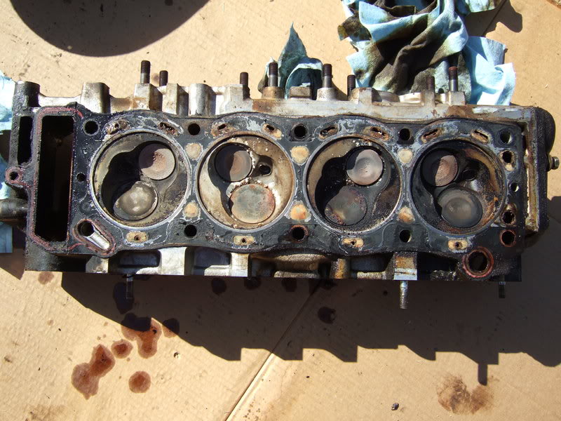
Lots of good info, and coming along nicely. You definately got coolant into cylinder 2. Looks like the passages around the cylinder are a little blocked, corroded. 3 certainly is a burnt exhaust valve. Bummer on that. What you doing with the head? replace or clean-up/valve job? I used straight hi-temp engine paint when I did block, no primer. It'll be superclean when you get the block back from the shop. As for your exhaust manifold, I did mine with hi-temp silver/fake aluminum color. What some guys do on 4x4wire, believe it or not, is to brush on old bacon grease, throw the manifold in the oven for 30 mins or so to really work in. Manifold will come out a beautiful black, and stay that way for a long time. I'm doing it the next time I ever have it off. Have you removed the bearing caps and removed the crank yet? Be sure to post pics of the bearing surfaces as they come out. Give me a hollar if you need help with re-assembly. I'm no expert, only rebuilt 1 22RE, but, no issues with 30,000 miles AND its a daily driver. Take care, Staceman.
10-07-2009, 07:50 PM
#32
Registered User
Thread Starter
Hi Stace,
I'm going to buy a new head from Engnbldr, most likely his Street/RV head. And probably add in his 268 cam. Even if mine were to pressure test ok and be fixable, I'd still wonder what hidden damage/thinning/weakening would be lurking from 23 years of electrolysis.
I'll read about that grease idea. It seems similar to seasoning cast iron cookware.
I'll get the crank out in the next day or two and will post pics of all the bearings. If anyone wants more pictures of anything in particular, or ones I've posted that aren't scaled down to 800x600, let me know.
I'm hoping to get parts to the shop Saturday, or failing that, as early next week as I can arrange transportation.
Thanks for your offer to help. Feels good knowing I have some backup if I get stuck.
10-08-2009, 06:19 AM
#33
Registered User
Join Date: Oct 2009
Location: NW Phoenix
Posts: 134
Likes: 0
Received 0 Likes
on
0 Posts
I wonder what my wife would think by finding the manifold in the oven? It would probably go over as well as the time I cleaned my timing cover in the dishwasher
10-08-2009, 12:33 PM
#34
Registered User
Thread Starter
Buy her a new unseasoned cast iron skillet or dutch oven. When you season her present, sneak your manifold in on the bottom rack. That should at least prevent a black eye.
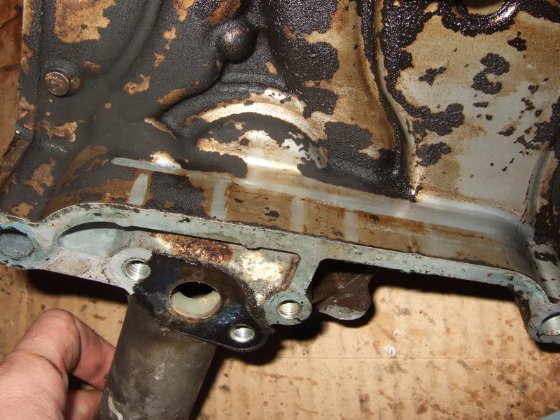
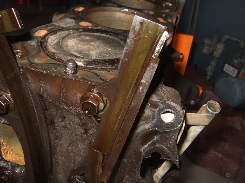
My timing cover isn't wanting to come off even after a decent beating. It moves a tiny bit, with great effort, in the area where the water pipe sticks out. I took out 10 bolts plus the two from the oil pan.
My timing cover isn't wanting to come off even after a decent beating. It moves a tiny bit, with great effort, in the area where the water pipe sticks out. I took out 10 bolts plus the two from the oil pan.
10-08-2009, 01:23 PM
#35
Registered User
Join Date: Oct 2009
Location: Virginia Beach
Posts: 95
Likes: 0
Received 0 Likes
on
0 Posts
stuff the ports full of cinnamon roll dough at least and pretend you were cooking and tell her it was all you could find that was clean.
10-08-2009, 02:01 PM
#36
Registered User
Thread Starter
As I suspected, I was missing a bolt -- the one by the oil pressure relief. I clarified the diagram posted above. Plus, in the upper right they point at a water pump nut instead of the proper bolt that also holds the alternator bracket.
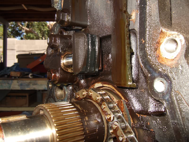
It's hard to tell from this pic, but there isn't much wear from the chain.
But, the driver's side guide is a mess. The top half fell off when I removed the cover. The passenger side is loose on its top bolt.
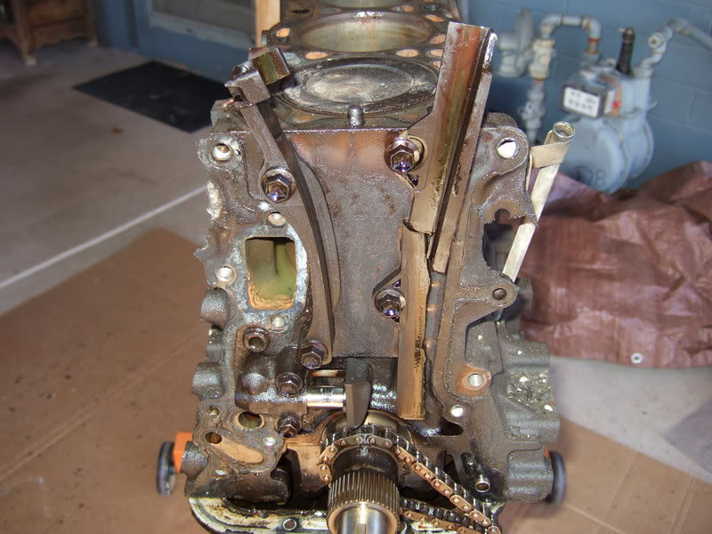
It's hard to tell from this pic, but there isn't much wear from the chain.
But, the driver's side guide is a mess. The top half fell off when I removed the cover. The passenger side is loose on its top bolt.
10-08-2009, 02:07 PM
#37
Registered User
Join Date: Jun 2009
Location: Iowa City, IA
Posts: 66
Likes: 0
Received 0 Likes
on
0 Posts
Anyone heard of Calyx? I never tried it, but I considered using it on my exhaust manifold. You can apply without having to remove the manifold, so no oven required.
Calyx Manifold Dressing
I love bacon, but I'm leery about cooking it on my exhaust manifold!
Calyx Manifold Dressing
I love bacon, but I'm leery about cooking it on my exhaust manifold!
10-08-2009, 03:37 PM
#39
Registered User
Thread Starter
She didn't have much, if any, care the first part of her life. It's a 1986 I bought in 1993. Even back then the inside of the valve cover had that crud built up.
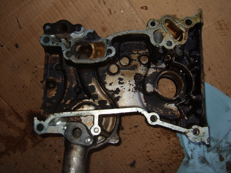
I heard timing chain guide parts fall as I flipped the engine over. The oil pan came off easily. I slightly sharpened the edge and rounded the corners of an old putty knife. I tapped it in gently about half the thickness of the pan lip all around. The pan popped right off after the second pass.
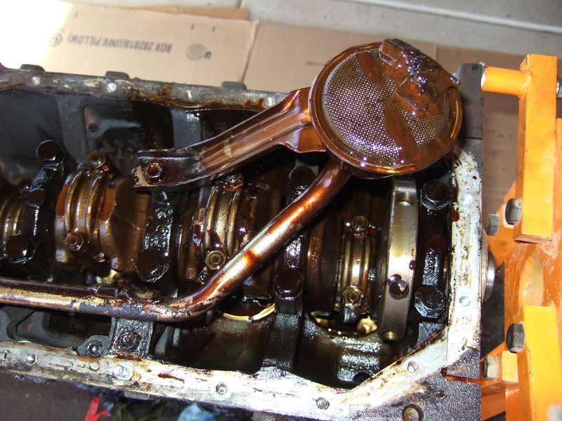
Notice the sealant is gray. I thought Toyota's FIPG for pans is black.
Earlier I noticed piston #4 in particular sticks up relatively high above the block. Factory specs for quench are 0 to +.006". Since there is some crud on the block and pistons, I couldn't get an accurate measurement, but a .016" feeler slid in under a square with room to spare. #4 had unusually high compression, and I'll bet this is why. #1's quench seemed to be about .007". I didn't check #2 or #3. I'll have to mention this difference to the shop and find out how they intend to address it.
How should I number the rod ends and caps before removing? Hammer and screwdriver?
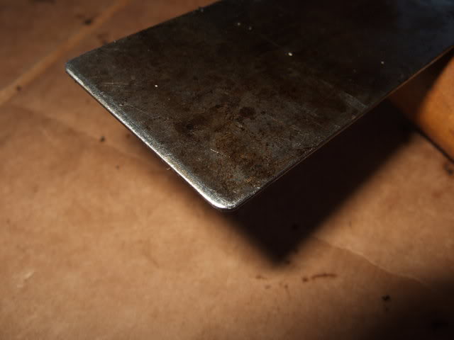
I heard timing chain guide parts fall as I flipped the engine over. The oil pan came off easily. I slightly sharpened the edge and rounded the corners of an old putty knife. I tapped it in gently about half the thickness of the pan lip all around. The pan popped right off after the second pass.
Notice the sealant is gray. I thought Toyota's FIPG for pans is black.
Earlier I noticed piston #4 in particular sticks up relatively high above the block. Factory specs for quench are 0 to +.006". Since there is some crud on the block and pistons, I couldn't get an accurate measurement, but a .016" feeler slid in under a square with room to spare. #4 had unusually high compression, and I'll bet this is why. #1's quench seemed to be about .007". I didn't check #2 or #3. I'll have to mention this difference to the shop and find out how they intend to address it.
How should I number the rod ends and caps before removing? Hammer and screwdriver?
Last edited by flyingbrass; 10-08-2009 at 06:21 PM.
10-08-2009, 06:17 PM
#40
Registered User
Thread Starter
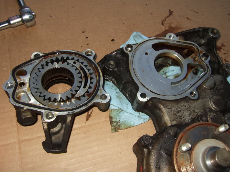
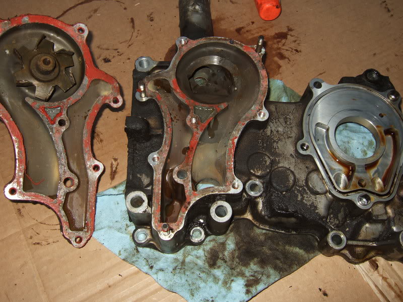
My oil pump measures ok according to the FSM (LU section).
Gear to body: .005" (max is .008)
Inner to crescent: .007" (max .012")
Outer to crescent: .009" (max .012")
Side clearance: .003" (max .006")
I'll check the new one when I get it and compare.
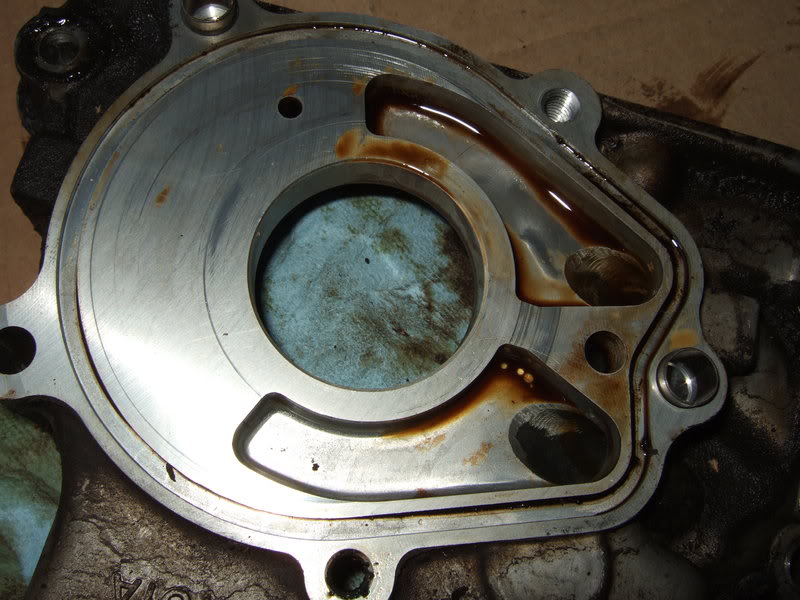
I'm surprised how good my water pump looks. The bearings feel snug and smooth, no wobbles or slop.
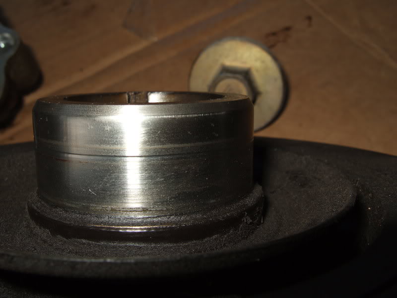
This so far is the best picture I've managed of my crank pulley. Is the groove deep enough that I should sleeve it?
Gear to body: .005" (max is .008)
Inner to crescent: .007" (max .012")
Outer to crescent: .009" (max .012")
Side clearance: .003" (max .006")
I'll check the new one when I get it and compare.
I'm surprised how good my water pump looks. The bearings feel snug and smooth, no wobbles or slop.
This so far is the best picture I've managed of my crank pulley. Is the groove deep enough that I should sleeve it?


