When you click on links to various merchants on this site and make a purchase, this can result in this site earning a commission. Affiliate programs and affiliations include, but are not limited to, the eBay Partner Network.
I will start off by saying, I'm slightly terrified of electrical work, mostly because I don't feel confident doing it and the fear of seeing my truck in flames by my own doing would be hard to manage.
I have been doing a lot of reading and was hoping someone would double check my plan to upgrade my alternator and wiring. It seems rather straight forward but like I said, I'm not super confident either. I know this is rather simple, so please go easy.
I am running 2 AWG ground wires, and a new 2 AWG positive wire from the alternator to the battery directly, with an inline 150 Amp fuse.
From my understanding this should remove the extra load going through my fuse box and fusible link/wire that currently is charging my battery and running my amp. The battery should now be able to charged directly from the alternator and run the amplifier with out pulling through the fuse box, leaving the original fuse box to handle all of the stock things it was intended for.
Am I on the right track here? I attached a diagram of my plan:
O.P.,
Glad you asked. You're on the right track, except... Like Wyoming says, remove the 8AWG wire. It bypasses your fusible link. It is unsafe.
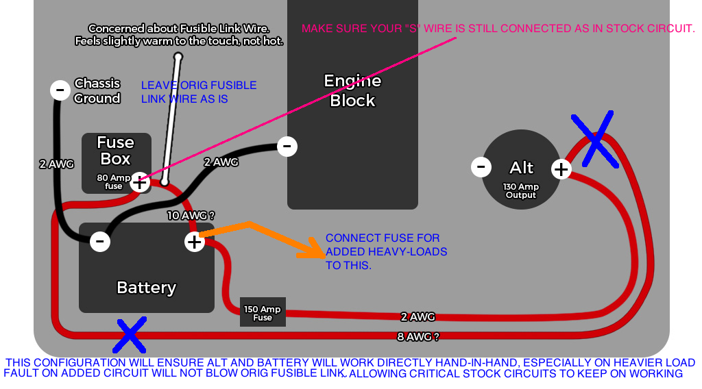
Wiring below is how Redeth, Chefyota and I wired ours - exactly like your plan, less the 8AWG wire:
Battery and alt will always directly work together. Shorts in aded circuits like winch, lights, compressors, etc will not blow fusible link so they will not affect critical stock circuit functions (ignition, fuel, ECU).
In other words, it will do what you're trying to do.
... remove the extra load going through my fuse box and fusible link/wire that currently is charging my battery and running my amp. The battery should now be able to charged directly from the alternator and run the amplifier with out pulling through the fuse box, leaving the original fuse box to handle all of the stock things it was intended for.
Double-check that "S" and IG" wires are still connected as in stock.
Since you're upgrading "B" wire, I assume you would be totally removing the stock, and tired, "B" wire.
Originally Posted by dropzone
what alternator did you use?
i need to upgrade the wimpy stock POS on my 94 V6 4runner
Robb,
Pls also check out Chef's thread. I believe he used 130-Amp. Wired like Redeth's and mine.
Last edited by RAD4Runner; 10-10-2015 at 12:33 PM.
Dropzone, Thanks for moving my thread I ordered up the 130 Amp alternator from LCE Engineering. Its on the expensive side, but I wanted a direct fit with a warranty. My current alternator is going out and this seemed like a decent option and good timing to upgrade, hope it turns out to be a good choice..
wyoming and RAD4Runner, thanks for the help! So I get what your saying, but I'm not fully clear on the benefit of removing that B wire instead of the fusible link wire. It would be unsafe to keep the B wire powering stock stuff, while the new positive 2 AWG charges, starts and powers accessories? Am I wrong in thinking that the fusible link wire is kind of thin to be the only thing supplying power to the fuse box? Currently the B wire I assumed handled most of the current to fuse box when the engine is running.
I tried to follow your post RAD about your new setup, so thanks for documenting all of that
If I do remove the B wire, would it be smart to replace the fusible link wire with new stuff? It seems a little tired looking. The B wire actually looks pretty good.
Most happy to help.
Stock "B" wire is wired same as the 8AWG in your original plan. You need to decide whether to connect New "B" wire (the 2AWG) like stock or as in our plan above.
With upgraded alternator, and especially with higher capacity batteries later, I do not recommend stock wiring for new "B" wire (2AWG). Why:
1) Higher battery capacity (or dual-battery setup) would also mean high charging current - higher than what the stock FL is designed for,
2) Heavy load like your amp from battery post would also draw more current through the stock FL - explains why FL gets warmer than usual.
3) If you look at my "worst-case scenarios" post, you would see why keeping "B" wire in stock position would not be safe with a 130-Amp alt combined with heavy non-stock circuits.
Also, if you research GM alternator circuit, I believe they are similar to our plan above- Alt should charge batt through the 150-amp fuse, not through the stock FL.
No need to replace stock FL because with your plan above it will only handle what it was originally designed for and minus charging current.
Just make sure FL wiring is clean and in good condition. If you need replacement FL, try Summit Racing. That's where I got mine from. Replace with exactly same rating to protect stock wiring.
Last edited by RAD4Runner; 10-10-2015 at 03:04 PM.
I finally got all my parts in order to finish this job, and started rewiring today. I discovered that the stock charge wire from the alternator to the 80 amp fuse, actually has a split before the fuse going into two other locations of the fuse block. Now my plan to just remove the stock B wire is not as simple. Did you run into this, if so how did you solve it? My thinking now is to remove the B wire up to the split, and retain the stock split, letting the current flow back through the 80 amp, into the other fuses through the splits. Hard to explain so here is a picture!
Would really appreciate your thoughts on this, thanks again!
RAD, thanks for the clarification.
actually has a split before the fuse going into two other locations of the fuse block.
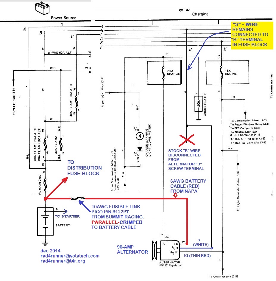
That split is where the "S" wire taps into the "B" circuit (the "B" line on the schematic). It's the red "X" in schematic below. The thin white wire at that crimp should be the "S" wire. I suggest you verify by physically tracing it. It should go to the "S" pin on alternator connector.
If so, yes, just cut stock "B" alt to batt wire at that split/crimp, and remove other end from the alternator "B" screw post. Replace with new , thicker wire connected to your 150-amp fuse. The "S" wire will remain connected to the fuse block though the short span of stock "B" wire. It will not carry high current. It merely allows regulator to Sense actual battery voltage.
Final circuit should look like below. The split/crimp would be the red "X".
(Mine uses 90-amp alt so pls ignore my wire gauge and FL rating)
I had an issue with those 2 splices that come off the main alt wire, when the alternator overcharged and fired the main wire by the fuse box. Make sure you get both of those splices back in the mix. https://www.yotatech.com/forums/f131/lights-out-266855/
I had an issue with those 2 splices that come off the main alt wire, when the alternator overcharged and fired the main wire by the fuse box. Make sure you get both of those splices back in the mix. https://www.yotatech.com/forums/f131/lights-out-266855/
I read your post, Yes. Quite possible that that the wire you missed was the "S" wire. IF "S" terminal of alternator/regulator is not connected to battery positive regulator will think that battery voltage is zero and would send more charging voltage out, causing overcharging of battery and possible overheating of wires.
I want to apologize in advance for my lack of understanding here, as I feel like I am probably missing some basic key element and wanted to run a few more diagrams past you to help be better understand if you have a free moment.
I spent a lot of time yesterday tracing wires like you suggested, and comparing them to the wiring diagrams you posted. I am having a hard time matching them exactly to how my truck is laid out. I am wondering if maybe the wiring is connected slightly differently for my 88 3vze than from the diagram you are posting. Or more likely, I just don't understand the layout of the wiring diagrams and how they are displaying splits and connections of wires.
I did get everything back together and the truck started up and everything seems good. But just in the name of safety, I was hoping to better understand why my layout doesnt look exactly the same.
Problem I am facing:
My S wire does not split off the B wire before any fuses, like it seems to in the diagram you posted. My S wire comes off the 40 amp fuse, and also splits to an unknown location. If you look at my updated diagram, i believe the concept is the same as what you are suggesting, keeping the S wire in stock function. I am really just trying to understand the layout, so I could be more confident in the work I did and hope to get your sign off on it
I have attached 3 pictures, one of the Stock layout, one of my new layout, and one extra of a picture of my fuse box with labels, probably not helpful or needed but, I am a visual person it I thought it might help.
Thank you again for all of your help!
Edit: I am starting to think that the two ? wires i have labeled on there might be connected to each other, and pass through the fuse block so you can break the connection if needed for some reason? This would technically be the direct connection from the B wire to the S wire i was looking for right? HMM!!!!! Wish I could test this right now. They were just in totally opposite sides of the truck so I didnt see why they would run all that wire to make a short loop like that.
Here is a wiring diagram I found searching that has that same direct connection even in the 88..
Edit #2:
Well staring at that above diagram, I am even more confused at this point. I count 5 separate wire splices from into the B wire on the alternator. I only found 2 spliced in wires on mine. I hope I am reading this wrong.
No problem, Man. Better to ask questions before wires melt/burn
Don't worry. You're good as long as:
(1) You made absolutely sure that your new B wire is connected only between battery/150-amp fuse and your Alt B screw post, and nothing else, AND
(2) You completely remove the stock B-wire up to that splice.
Your S wire is still connected to the battery through proper fuses.
Unfortunately, schematics of older models do not reflect physical location of splices. (for example, schematic shows S as connected to B near the battery when in reality it is spliced near the fuse block.)
Good job on sketching your stock and new wiring. I suggest you keep a copy attached to the stock wiring for future reference.
RAD, thanks for all of your help. I found myself reading though your build yesterday, made it all the way through. Great job on your 4runner, love the way you are trying to keep everything nice and clean. The truck looks great!
RAD, thanks for all of your help. I found myself reading though your build yesterday, made it all the way through. Great job on your 4runner, love the way you are trying to keep everything nice and clean. The truck looks great!
Most welcome with lots of pleasure- and thanks!
Still lots of restoration/enhancement to do, but she runs really well, so she's a daily-driven project
This is perfect, outside of the fact that I have an 86' 22RE, this is perfect. I'm in the collecting parts and planning phase of my battery/Cressida AFM swap, big 3 upgrade, XJ6 Jaguar alternator swap with the intention of doing it over thanksgiving weekend.
Been driving the truck for the last week, and so far so good. I did have a few small concerns I was hoping to share and see if they are worth worrying about.
1. Is there any worry about the alternator over charging the battery by sending too high of a voltage with this new layout? Say while using all accessories in the cab with the high beams on. White idling at the battery I'm measuring 14.5v with nothing on, and 14.67v with headlights.
2. My fusible link wire from the battery to the 80 amp fuse is getting warm and I don't like it. It is possible since I never thought to check the temperature of this wire before hand, its probably been this warm all along. I cant help but think that now this wire is carrying all of the load to the truck at all times when running, it is being stressed. I spent some time today cleaning up the entire wire and connections around it. I installed a new 12 gauge fusible link wire inline from the battery to the wire coming off the 80 amp fuse with new ring terminal and all. See pic below. Funny enough the 8 gauge wire coming off the 80 amp fuse is actually getting slightly warmer. I guess because of how old and tired it must be. When i stripped it back to splice in a new connection, the copper seemed relatively clean though. Have you guys noticed your fusible link wire being warm to the touch? Warmer than other surrounding wires that are at ambient engine bay temp. Its not HOT, I have no problem keeping my fingers on it. I'm just not familiar enough with how hot is too hot.
Glad you found some use from this paynemw!
I would of liked to replace the old stock 8 gauge wire, but I could not think of a good way to re-attach wire to that special plate that bolts onto the 80 amp fuse.
If you only have stock loads being supplied though fusible link, you should be fine. Is that the case?
Theoretical reason for high voltage at battery is as follows:
"S" wire is supposed to sense actual battery voltage. However, currently it is not directly connected to the battery post. Instead it is connected downstream of a couple of fuses and wires which have little but some resistance. As current goes downstream through that series of wires and fuses, a voltage drop develops across the that series. Therefore, voltage reaching the "S" wire is reading slightly lower than actual battery post voltage. That causes regulator to bump up charging voltage. When you turn your headlights on, it causes more current to pass and increases the voltage drop across that series of wires and fuses. Therefore, "S" senses lower voltage and tell regulator to pump out a little bit more.
22RE FSM says, with engine from idle to 2000RPM, Voltages at B should be:
13.9 to 15.1 V @25�C (77�F)
13.5 - 14.3V @115�C (239�F)
Temp is probably engine compartment temp.
I do not know exact target "B" voltage of regulator but I'm guesstimating 14.3V (middle of range from 13.5Vmin to 15.1V max). If you can measure voltage exactly where "S" wire taps into the fuse block I think that's what you will get.
Good job replacing the FL. It's possible that the stock wires have gone brittle, somehow corroded and some strands may have been broken, giving that span of wire a higher resistance - causing it to get hotter than normal.
As for that plate, you can simply keep that plate, it's just a convenient way to electrically jump the two terminals together. To replace, simply use a terminal lug on replacement FL wire and put everything back together, keeping the plate as jumper. You may need a slightly longer screw in order to hold the new terminal lug.
Last edited by RAD4Runner; 11-01-2015 at 04:29 PM.
I do have nearly stock loads, the only difference would be the stereo head unit and 4 speakers that are wired through it. But the FL wire gets warm/hot regardless if the stereo is on or not. I have some HELLA brand headlights I put in several years ago, I don't recall if they are any higher output, but i really doubt it, as they are pretty dim compared to any car these days. They are not the conversion type, just full glass replacements.
Good idea on just clipping off the 80 Amp fuse plate connection and having the Fusible Link wire bolt directly to the plate, not sure why that did not cross my mind Funny how the obvious simple answer fades away when your looking at the the complicated solution.
I will replace the tired white wire tomorrow, check the temp and also see if i can get the S connection voltage checked and report back. Thanks again Rad for all of your help.
 10-09-2015, 05:36 PM


 I ordered up the 130 Amp alternator from LCE Engineering. Its on the expensive side, but I wanted a direct fit with a warranty. My current alternator is going out and this seemed like a decent option and good timing to upgrade, hope it turns out to be a good choice..