Alternator charge cable
 11-29-2014, 09:41 AM
#1
Registered User
Thread Starter
iTrader: (1)

Join Date: Aug 2013
Location: Livonia, MI
Posts: 110
Likes: 0
Received 0 Likes
on
0 Posts
Alternator charge cable
So I've been doing some upgrades to my runner, one being a new HO alternator from LCE. My question is how do I replace the charge cable going from the alternator to the fuse box?
I've searched and can't seem to find a good guide. I traced the wire and it seems to have a bunch of wires coming off of it. I'm terrified of electrical stuff so I didn't tear into the sheath. Has anyone done it and can give me a basic walk through. I didn't see an easy way to remove the wire from the fuse box either.
Also I replaced my alternator cause in planning on a winch but I also had my voltmeter fluctuate with my blinkers. I thought the alternator would help with that but it didn't. Any advice?
1985 4Runner 22re
 11-29-2014, 02:22 PM
#2
First always disconnect the negative battery cable.
Rather then trying to remove the old wire from the plastic conduit or split loom I just get a new piece of split loom to run the new wire through.
Then cable tie it to the existing harness.
once the new wire is installed I cut the old wire off as close to where it joins the harness.
Because this wire carries all the current from the alternator it is bolted to the underside of the fuse block .
unbolt fuse block so you can see the bottom some still have a cover on the bottom most are long gone if the cover is stll on remove it you will see the connection.
Make sure the new wire has the correct size ends to fit where they attach to
Connections need to be tight and clean loose connection heat up..
***The wire Is of ample size to carry the load of the alternator ..
Now some people are so perfect that it all needs to look perfect so will then spend a whole day removing the old wire and placing the new wire in the original split loom.
This should give you a good idea of how to do this.
Last edited by wyoming9; 11-29-2014 at 02:24 PM.
11-30-2014, 06:36 AM
#4
It won`t hurt.
With age and thermal cycling those cables get brittle and conduct less and less
Once the whole charging system has been upgraded you should be good .
Quite a few times the factory Voltmeter is not the accurate so even when all is new you still get the needle deflection.
Where a Voltmeter at the battery does not deflect.
11-30-2014, 09:18 AM
#5
Get this if you do not want to wire in an after-market volt-meter. Does not measure directly from the battery posts but still a good indicator of your charging system's health....
11-30-2014, 03:48 PM
#7
MI bought batery cable by the foot from NAPA. Just replace it with same length from alt to battery. Delete the disconnect that looks like a ferrite choke near the ignition coil; it's unnecessary and a potential point for failure. Best to replace it all the way to fuse block where it screws into a terminal. Watch where the thin White "S" wire goes and make sure it's reconnected. Make sure u have clean and secure terminal crimps. I used Harbor Freight hydraulic crimper. Dries wrongly labelled but I I just picked what size looked best. Then, fluxed. And soldered using 80-watt iron, supplemented with heat gun blowing on crimp. Seal crimp with liquid tape and heat-shrink or adhesive-filled Heat-shrink.
Trending Topics
12-29-2014, 09:30 PM
#8
Registered User
Thread Starter
iTrader: (1)
Join Date: Aug 2013
Location: Livonia, MI
Posts: 110
Likes: 0
Received 0 Likes
on
0 Posts
still haven't gotten around to it but had a couple more questions. Does the charge wire need a fusible link? what is that? sorry for the stupid questions
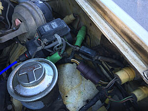
also is this the ferrite choke and what's it for?
also is this the ferrite choke and what's it for?

Last edited by Yont283; 12-29-2014 at 10:48 PM.
12-30-2014, 12:46 AM
#9
Here's how I did mine for a 90-Amp alt, using 6AWG battery cable and 10AWG fusible link.
IF you keep alt-to-batt (B) wire running as in stock circuit you would not need a fusible link. In case of a short, fusible link will blow but not catch fire before the rest of the wiring downstream melts or burns. Easier and safer that way. Easier to replace a fusible link than find where wiring melted, replace burned wiring, or replace a burnt truck 
If you upgrade to a higher capacity alt, it's best to wire it like Redeth, Chefyota and I did (see above), where "B" wire is connected directly between battery and alt, without passing through the fuse bock network. In fact, this is same as the way GM system is wired (here). This setup will take care of worst-case-scenarios discussed on my post.
IF you wire it like we did, then you would need to use a fusible link on the "B" wire as close as possible to battery. [GM system does not have it, but that's why Toyota is better.]
You need to determine what is optimum wire gage to use for your alt capacity. Then find the right fusible link. General rule for "B" wire is wire gauge handle your alt capacity and fusible link 4 gauges thinner than the battery cable. Example: My "B" cable is 6AWG, so I used 10AWG fusible link from Summit Racing (here).
Not stupid at all because that little thing is deceiving. It looks like a choke but it is not. It is really a disconnect, which had been proven unnecessary and is just another potential point of failure (here). As you can see, I got rid of it.
Best of luck with the project and happy new year.
If you upgrade to a higher capacity alt, it's best to wire it like Redeth, Chefyota and I did (see above), where "B" wire is connected directly between battery and alt, without passing through the fuse bock network. In fact, this is same as the way GM system is wired (here). This setup will take care of worst-case-scenarios discussed on my post.
IF you wire it like we did, then you would need to use a fusible link on the "B" wire as close as possible to battery. [GM system does not have it, but that's why Toyota is better
.]You need to determine what is optimum wire gage to use for your alt capacity. Then find the right fusible link. General rule for "B" wire is wire gauge handle your alt capacity and fusible link 4 gauges thinner than the battery cable. Example: My "B" cable is 6AWG, so I used 10AWG fusible link from Summit Racing (here).
sorry for the stupid questions also is this the ferrite choke and what's it for?
Best of luck with the project and happy new year.
12-30-2014, 05:55 PM
#10
Registered User
Thread Starter
iTrader: (1)
Join Date: Aug 2013
Location: Livonia, MI
Posts: 110
Likes: 0
Received 0 Likes
on
0 Posts
RAD4Runner, thank you for the info! My HO alternator from LCE should be here soon and I will def be doing this - have plans for a winch, leds, and upgraded headlight harness.
Is there anything to put on the terminals so it's easier to add lights and the winch?
Is there anything to put on the terminals so it's easier to add lights and the winch?
12-30-2014, 06:37 PM
#11
Dell city has a lot of nice quality battery terminals and other electrical stuff. You can get battery terminals with a solder plug installed that you heat with a torch and plug your wire in. Work great!
12-30-2014, 08:09 PM
#12
Registered User
You should also add a couple extra NEG ground wires.
Alternator to chasis and chasis to motor.
Also NEG ground wires; battery to body and body to frame.
Alternator to chasis and chasis to motor.
Also NEG ground wires; battery to body and body to frame.
Last edited by FrankTorres; 12-31-2014 at 04:56 PM.
02-15-2015, 08:56 PM
#13
Registered User
Thread Starter
iTrader: (1)
Join Date: Aug 2013
Location: Livonia, MI
Posts: 110
Likes: 0
Received 0 Likes
on
0 Posts
alright so all the wiring is done!
0 awg everywhere wired up like RAD4Runner suggested.
no I have a bit of an odd problem. When I start the truck and it's cold, like below 20 cold, my charge light and parking brake light come on.
I have a new alternator (high output from LCE) and a newish battery (<1year). After like 5-10 minutes the lights go off. I had the alternator checked and its good so what's happening? they said my battery was not all the way charged up but it's been below zero here so I dunno.
any ideas?
02-15-2015, 10:16 PM
#14
Yont,
Temp-dependent sounds sounds like something with battery chemistry. Got ti tested?
Pls measure voltage at B post when you get the charge error. IF it's outside 13.5 - 15.1 Volt range, then Alt circuit is doing its job.
Temp-dependent sounds sounds like something with battery chemistry. Got ti tested?
Pls measure voltage at B post when you get the charge error. IF it's outside 13.5 - 15.1 Volt range, then Alt circuit is doing its job.
02-16-2015, 12:06 PM
#16
Registered User
Thread Starter
iTrader: (1)
Join Date: Aug 2013
Location: Livonia, MI
Posts: 110
Likes: 0
Received 0 Likes
on
0 Posts
belt seems to be just right.
i trickled charged the battery today and when I started it - No light!!
got the battery tested at AAP and its a 650 cca battery that was testing at 330 cca after the truck had been on for a while.
going back now to try and get a replacement.
The voltage was 14.5 amps with the truck on and no light. Haven't had a chance to test it with the light on. Will update.
also, my tachometer doesn't work when it's below freezing! I think my truck hates MI.

Thread
Thread Starter
Forum
Replies
Last Post
kawazx636
The Classifieds GraveYard
34
10-06-2021 03:03 PM


