When you click on links to various merchants on this site and make a purchase, this can result in this site earning a commission. Affiliate programs and affiliations include, but are not limited to, the eBay Partner Network.
I have searched and searched. Truck was flooded and headlights won't work. All clearance lights do. Relays are good. Where does power from battery go first? Is it to relay and if so which terminal. Thinking I might need to run a new hot wire. Headlights are new by the way.
Last edited by sandman666; 09-27-2016 at 03:14 AM.
i have 2 relays behind dash on firewall, for headlights. are those the 2 you checked? do you hear them click when you turn on lights?
when I turn on headlights one of the relays clicks. Am I correct in saying one is for clearance/tail lights and one would be for headlights? I switched the 2 relays and still same outcome when I turn on headlights. So I assume relays are good. I ordered a new combination switch but I'm afraid that won't fix problem. I am curious as to how the circuit runs. Battery to relays to switch to fuse or how?
You don't mention the year but I have a diagram here for an 82. Appears the headlight relay gets its power through a fusable link direct from the battery, per my diagram the same link feeds the hazard and horn, do those things work? From the relay they then go through the headlamp fuses and obviously onto the headlamps.
You don't mention the year but I have a diagram here for an 82. Appears the headlight relay gets its power through a fusable link direct from the battery, per my diagram the same link feeds the hazard and horn, do those things work? From the relay they then go through the headlamp fuses and obviously onto the headlamps.
81. Hazards and horn don't work either and I don't have power to the headlight fuses. Does your diagram give a description of the hot wire from battery to relay? Color? Stripe? Etc
On my 81 wiring diagram, the Headlight relay and the Horn/Hazard fuse is powered thru the Fusible link at the battery, wire colored Red/Blue stripe. Check the connection at the battery first, as corrosion might have set in. clean and retry. I would then check the fusible links for continuity or voltage with a multimeter or test light. You can also use your fingers by running over the length of link, feeling for a bulge or broken section of wire. To bypass, I've used a piece of 12 -14 gauge wire with clamp on each end, hook up between battery hot and the fuse under dash. If there is power, then you have an open between the fuse and the battery, most likely at the fusible link
Yeah those fusible links are prone to failure over time. I think replacements are available in the help section at most auto parts stores. On my 78 they were long gone, I replaced them with circuit breakers.
On my 81 wiring diagram, the Headlight relay and the Horn/Hazard fuse is powered thru the Fusible link at the battery, wire colored Red/Blue stripe. Check the connection at the battery first, as corrosion might have set in. clean and retry. I would then check the fusible links for continuity or voltage with a multimeter or test light. You can also use your fingers by running over the length of link, feeling for a bulge or broken section of wire. To bypass, I've used a piece of 12 -14 gauge wire with clamp on each end, hook up between battery hot and the fuse under dash. If there is power, then you have an open between the fuse and the battery, most likely at the fusible link
ok. Fuseable link was bad. So was combination switch. Ordered one for an 82 since I couldn't find one for an 81 w\o tilt. Plug was wrong so I took the two apart and made one. Then I blew the relay. And of course nobody stocks one. But the halos sure are pretty!!!!!
ok. Fuseable link was bad. So was combination switch. Ordered one for an 82 since I couldn't find one for an 81 w\o tilt. Plug was wrong so I took the two apart and made one.
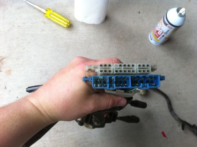
Post a pic of what you did to make the plug work, it would be cool to add the info (posting the info below in case someone searches for a similar issue)
Originally Posted by dropzone
so just because you have a 1st Gen truck, there are differences between the 79-81 and 82-83 that are not as obvious as the round and rectangular headlights;
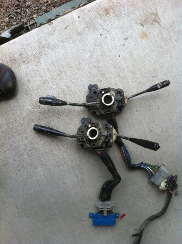
Found this when swapping steering columns today:
the light/wiper switches look the same-
81 switch plug in on top, 82-83 is on the bottom
Post a pic of what you did to make the plug work, it would be cool to add the info (posting the info below in case someone searches for a similar issue)
i didn't change plug just the headlight switch itself. Had to splice 3 wires and drill new hole for pin. I bought the 82 switch because you can't find a switch for an 81 without tilt. Was hoping they used 82 parts on my 81
Yeah those fusible links are prone to failure over time. I think replacements are available in the help section at most auto parts stores. On my 78 they were long gone, I replaced them with circuit breakers.
I recently had the same problem. It also turned out to be the fusible link. While fixing that I found that one of the other links had also blown. It was the one that goes to the ignition switch. Which was weird because the truck shouldn't be able to start without it. Hmmm. Long story short, it turns out that the P.O. had run a jumper wire from the hot lead on the alternator to the ignition switch to bypass it. Grrr, more sketchy wiring to fix I guess. Picked up an automotive electrical connector removal tool and the proper gauge fusible link wire from NAPA (they were the only ones that had it) and with a little soldering had it all back together. To the point, Rowdy235 what type of breakers did you use? I searched quite a bit and didn't come up with any great solutions. I would love to see what you came up with as I'm sure many other first gen folks would as well so we can ditch those pesky fusible links. Thanks! (sorry not trying to hijack).
I recently had the same problem. It also turned out to be the fusible link. While fixing that I found that one of the other links had also blown. It was the one that goes to the ignition switch. Which was weird because the truck shouldn't be able to start without it. Hmmm. Long story short, it turns out that the P.O. had run a jumper wire from the hot lead on the alternator to the ignition switch to bypass it. Grrr, more sketchy wiring to fix I guess. Picked up an automotive electrical connector removal tool
and the proper gauge fusible link wire from NAPA (they were
the only ones that had it) and with a little soldering had it all back together. To the point, Rowdy235 what type of breakers did you use? I searched quite a bit and didn't come up with any great solutions. I would love to see what you came up with as I'm sure many other first gen folks would as well so we can ditch those pesky fusible links. Thanks! (sorry not trying to hijack).
turns out somehow my wireing to headlight plugs were wrong. Had hot on ground terminal. Cut switched and spliced wires WALAH!! Let there be light!!! Finally!!!
Good thread... a few questions since I just picked up this 83 and evidently someone thought fuses aren't really needed. grrr...
Can someone post the fusible link ratings or values for each circuit? Per the WD I downloaded here on YT, I see there are 3, but I can't really decipher what the indications are on the FSM. My truck currently has none!! (See image below)
There were no less than 5 crimps and 3 jumper wires coming off the positive post of the battery (not including starter wire), so I'm not sure what is from the stock harness... looks like I have a Red/Blue a Red/Black and a Yellow going into the harness right behind the battery. Can anyone confirm that is correct?
Can I just install a small fuse block near the battery to take the place of the links?
Where did you guys get the combination switch? Dealer? I may need one in the future, I broke the stalk to the right (wiper I believe), it was so brittle.
Thanks in advance...
award for the poorest lit photo I've seen all day.
#4, scrap yard, aftermarket or dealer (which will probably be aftermarket unless you get lucky and find NOS)
#3, can you yes, should you no.
#2,take a photo you'll get better results. You can usually gauge OEM wires by the striping method and the use of yakuzi wrap.
#1, again worst photo of the day. It's not the 80s man take clear well lit high-resolution photos, were not sending data over telegraph lines.. my oldest book is 85 it's a 120 primary, 80, 30 and 40 amp fusible link wire..
Thanks for the reply. Don't blame me for the lousy pic - that's all I have to work with man... that image is what was posted for "missing" page 1 of the wiring diagram on the first sticky in the pre-84 section here on Yotatech. If I had a better diagram I might not even have a question about it lol.
I'm on a flight for work, I'll have to snap a pic of the existing wires when I get home.
Could be wire gauge or color codes, if it is English. Not sure just makes my eyes hurt is all I'm certain about..
One of the attachments above shows a 14gauge (blue) FL that will be the 120amp directly off the battery. You can gauge the others downstream, note you measure the wire not the sheathing, then use one gauge smaller FL wire than what you're fusing.
We just covered these(fusible links versus fuses) the other day but to sum it up in short. FL wire is slow blow, fuses are typically instant blow. FL wire uses a fire rated (fire proof/resistant) sheathing. You don't want fire or sparks near the battery due to the explosive risk.
P.O. once you're figure out AWG's.. visit Summit Racing. That's where I got my Fusible link wire..
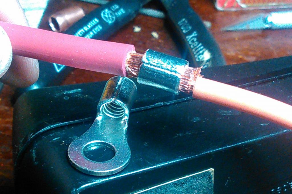
AND use parallel crimp connector as shown below, not butt-connector.
Originally Posted by Co_94_PU
award for the poorest lit photo I've seen all day.
LOL!
I did not want to buy bulk crimp connectors so I improvised...
Here is a sample of color code for fusible links. In my 81 wiring diagram, they show 2 green and one red links. That would mean that those circuits would need 40 and 50 amp links. This link is to a pretty good discussion on links and some good pics also..https://forum.ih8mud.com/threads/fus...8-bj40.526232/
There is also the norm that the fusible link protects 2 wire sizes larger circuit, ie; link with 14 gauge wire protects a circuit with 10 gauge wire. Hope this helps.
Here is a sample of color code for fusible links. In my 81 wiring diagram, they show 2 green and one red links. That would mean that those circuits would need 40 and 50 amp links.
Great info fellas. Lon, if you get time, would you mind posting a clear pic of that page of your wiring diagram? I have a hunch that your FL values are going to be the same as that crappy pic that I have been trying to work off of. Would like to confirm that if possible.
 09-27-2016, 03:12 AM